Table of Contents
Advertisement
Quick Links
Advertisement
Chapters
Table of Contents
Troubleshooting

Related Manuals for Hydro-Gear HGM-H Series


Summary of Contents for Hydro-Gear HGM-H Series
- Page 1 HGM-H™ Series Motor Service and Repair Manual BLN-0043 January 2018...
-
Page 2: Table Of Contents
TABLE OF CONTENTS Foreword . . . . . . . . . . . . . . . . . . . . . . . . . . . . . . . . . . .1 Assembly After a Complete Teardown . -
Page 3: Foreword
H e a d q u a r t e r e d i n S u l l i v a n , I l l i n o i s , Internal repair procedures require that the Hydro-Gear is a world leader in the design, HGM-H series motor be removed from the manufacture, and service of quality hydrostatic vehicle . -
Page 4: Description And Operation
. The HGM-H series motor is available with a fixed displacement of 15 cu. in. or 18 cu. in. (245 to 294 cc) maximum per revolution . The cylinder... -
Page 5: External Features
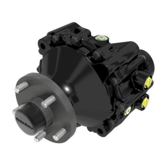
EXTERNAL FEATURES HGM-H SERIES MOTORS “B” PORT WHEEL HUB “A” PORT HYDRAULIC HOUSING CAP HUB NUT COVER BRAKE ARM FILL PORT / OPTIONAL CASE DRAIN — Top View— MOUNTING HOLE X 4 “B” PORT “A” PORT BRAKE ARM — Back View—... -
Page 6: Technical Specifications
38 .2 lb (17 .3 kg) PRODUCT IDENTIFICATION The model and configuration of the HGM-H can be determined from the label found on the transaxle . HYDRO-GEAR HGM-15H-XXCK 1 192 X 10428 Assembled in USA Date (Julian- Day of year) -
Page 7: Safety
SAFETY Wear appropriate clothing . Loose or hanging clothing or jewelry can be hazardous . Use the This symbol points out important safety appropriate safety equipment, such as eye and instructions which, if not followed, could endan- hearing protection, and safety-toe and slip-proof ger the personal safety and/or property of your- shoes . -
Page 8: Troubleshooting
TROUBLESHOOTING In many cases, problems with a hydraulic sys- WARNING tems are not related to a defective hydraulic unit, but are caused by slipping drive belts, Do not attempt any servicing or ad- partially engaged bypass valves, and loose or justments with the engine running. -
Page 9: Work Area Safety
. FLUIDS 2 . Check reservoir oil level in accordance with The fluids used in Hydro-Gear products have the vehicle manufacturers recommenda- been carefully selected, and only equiva- tions . lent, or better products should be substituted Typically, an engine oil with a minimum rating 3 . -
Page 10: Purge Procedure
SERVICE AND MAINTENANCE PURGING PROCEDURE WARNING The HGM-H motor can not be purged of air as a stand alone component . The hydraulic POTENTIAL FOR SERIOUS INJURY system as a whole will need to be purged after Certain procedures require the vehicle any addition of oil to the system or a complete engine to be operated and the vehicle to oil change . -
Page 11: Tear Down And Reassembly
. As with any precision equipment, all parts must be kept free of foreign material and chemicals . Note: “Any and all Hydro-Gear components removed and replaced during service are Protect all exposed sealing surfaces and open recyclable.”... -
Page 12: Tools
TOOLS RE QUIRED TOOL S Miscellaneous Sockets Three Jaw Puller 1/2”-3/8” Adapter Flat Blade Screw Driver (2) 3/8” Deep Torque Wrench 1-1/8” Deep Air Impact Wrench 1/4” Allen Rubber or Neoprene Mallet 3/4” Deep Breaker Bar Side Cutters/Snips Needle Nose Pliers Large External Snap Ring Pliers Small Internal Snap Ring Pliers TORQUES... -
Page 13: Hydraulic Motor Removal
MOTOR REMOVAL NOTE: It is necessary to remove the HGM-H Do not disassemble the unit any far- Motor from the vehicle before perform- ther than necessary to accomplish the ing the repair procedures presented in required repairs. this section. Reassembly is accomplished by per- Before starting any disassembly, make forming the “Assembly”... -
Page 14: Axle Hub Assembly
AXLE HUB ASSEMBLY Assembly Refer to Figure 4 1 . Remove the axle cap and discard (9) . 1 . Reassemble all parts in the reverse order of disassembly . 2 . Remove the cotter pin and discard (18) . 2 . -
Page 15: Brake Arm Assembly
BRAKE ARM ASSEMBLY Refer to Figure 5 Assembly Disassembly 1 . Reassemble all parts in the reverse order 1 . Remove all items previously discussed in of disassembly . their recommended order . 2 . Install new seal (58) from seal kit . 2 . -
Page 16: Side Housing
SIDE HOUSING Refer to Figure 6 Assembly Disassembly 1 . Reassemble all parts in the reverse order 1 . Remove all external items previously dis- of disassembly . cussed in their recommended order . 2 . Remove the seal (13) and discard . 2 . -
Page 17: Axle Shaft And Planetary Gear Set
AXLE SHAFT AND PLANETARY GEAR SET Refer to Figures 7 and 8 Assembly Disassembly 1 . Reassemble all parts in the reverse order 1 . Remove all external items previously dis- of disassembly . cussed in their recommended order . NOTE: Note the location of the ring gear tabs. -
Page 18: Bearing And Motor Block Cap
BEARING AND MOTOR BLOCK CAP Refer to Figure 9 Disassembly Assembly 1 . Remove all external items previously dis- cussed in their recommended order . 1 . Reassemble all parts in the reverse order 2 . Remove the seven housing cap screws (4) of disassembly . -
Page 19: Motor Block
MOTOR BLOCK Refer to Figure 10 Disassembly Assembly 1 . Remove all external items previously dis- 1 . Reassemble all parts in the reverse order cussed in their recommended order . of disassembly . 2 . Remove the motor block assembly (40) from 2 . -
Page 20: Motor Shaft And Brake Disc
MOTOR SHAFT AND AXLE BEARING Refer to Figure 11 Assembly Disassembly 1 . Reassemble all parts in the reverse order 1 . Remove all external items previously dis- of disassembly . cussed in their recommended order . 2 . Remove the motor shaft (34), retaining ring (30) and gear (31) out of the middle housing (2) . -
Page 21: Brake Shaft And Cam
BRAKE SHAFT AND CAM Refer to Figure 12 Disassembly Inspection 1 . Remove all external items previously dis- 1 . Inspect the puck (54) for excessive wear . cussed in their recommended order . 2 . Inspect all components for wear or dam- NOTE: If the brake is working properly and the age . -
Page 22: Screw Tightening Sequence
SCREW TIGHTENING SEQUENCE Figure 14, Motor Housing Cap Bolt Sequence Figure 13, Side Housing Bolt Sequence SEALANT PATH Figure 15, Sealant Path HGM-H... -
Page 23: Castle Nut Alternate Torque Method
CASTLE NUT (10) ALTERNATE TORQUE METHOD NOTE: The ideal method for installing a new hub and nut is utilizing a torque wrench capable of 275 ft-lbs. If a 275 ft-lbs torque wrench is not available please use the alternative procedure outlined in this document. All parts need to be clean and free of lubrication. Tools: Procedure: 1 . -
Page 24: Assembly After A Complete Teardown
ASSEMBLY AFTER A COMPLETE TEARDOWN If the unit has been torn down completely, the 8 . Apply sealant material onto housing middle following summary identifies the assembly pro- housing (2) . Page 21 cedures necessary to completely assemble the 9 . Install the axle housing (1), the 12 housing unit . -
Page 25: Drive Motor Exploded View
HGM-H MOTOR EXPLODED VIEW HGM-H... -
Page 26: Parts List
HGM-H MOTOR PARTS LIST Housing, Axle Housing, Middle Housing, Motor Block Screw, Housing O-ring, Motor Housing Cap, Axle Nut, Axle Hub, Taper (1 .25, 4 Bolt / 1 .25, 5 Bolt) Seal, Axle Bearing, Axle, Outboard Spacer, Axle Axle Key, Woodruff, Axle Pin, Cotter 5/32 X 2 Carrier Gear, Ring... -
Page 27: Glossary Of Terms
GLOSSARY OF TERMS Axial Piston: Type of design for hydraulic motors and pumps in which the pistons are arranged parallel with the spindle (input or output shaft) . Bypass Valve: A valve whose primary function is to open a path for the fluid to bypass the motor or pump . - Page 28 Integrated Zero-Turn Transaxle: The combination of a hydrostatic transmission and gear case in one housing to form a complete transaxle . Manifold: A conductor which provides multiple connection ports . Neutral: Typically described as a condition in which fluid flow and system pressure is below that which is required to turn the output shaft of the motor .
- Page 29 Series Motor Service and Repair Manual BLN-0083 January 2018...
- Page 30 TABLE OF CONTENTS SECTION PAGE SECTION PAGE Tear Down and Reassembly.....9-11 Foreword............1 How to Use This Manual.....9 General Instructions......9 Description and Operation......2-4 Tools..........10 Introduction.........2 Torques..........10 General Description ......2 Removal..........11 External Features HEM ....3 Technical Specifications......4 Product Identification......4 HEM Tear Down and Assembly...12-19 Speed Sensor Assembly....12 Safety.............5 End Cap Assembly......13...
-
Page 31: Foreword
Hydro-Gear HEM High ers in our industry. Efficiency Motor. For more information about Hydro-Gear or our Also included is a glossary of terms that are products, please contact your Central Service frequently used throughout the industry and in Distributor. -
Page 32: Description And Operation
The cylinder block pistons in the HEM motor are set at a fixed displacement by a swash The purpose of this manual is to provide in- plate angle. As pressurized fluid from the pump formation useful in servicing the Hydro-Gear ® pushes against the cylinder block pistons, they High Efficiency Motor. This manual are forced to rotate with the thrust bearing. -
Page 33: External Features Hem Tm
EXTERNAL FEATURES End Cap Speed Sensor (Optional) Motor Housing Shaft Case Drain “B” Port “A” Port Figure 1, External Features... -
Page 34: Technical Specifications
TECHNICAL SPECIFICATIONS Product Type 10.2cc 12.0cc Displacement 0.62 in per rev 0.73 in per rev System Operating Pressure Continuous 261 in-Ibf (29.5 Nm) 310 in-Ibf (35.0 Nm) Intermittent 324 in-Ibf (36.6 Nm) 386 in-Ibf (43.6 Nm) Peak 442 in-Ibf (49.9 Nm) 529 in-Ibf (59.8 Nm) Output Shaft (Diameter) 5/8”... -
Page 35: Safety
SAFETY This symbol points out important safety Wear appropriate clothing. Loose or hanging clothing or jewelry can be hazardous. Use the instructions which, if not followed, could endan- appropriate safety equipment, such as eye and ger the personal safety and/or property of your- hearing protection, and safety-toe and slip-proof self and others. -
Page 36: Troubleshooting
TROUBLESHOOTING In many cases, problems with a HEM motor WARNING are not related to a defective motor, but may be pump related problems. Be sure to perform all Do not attempt any servicing or ad- operational checks and adjustments outlined justments with the engine running. -
Page 37: Service And Maintenance
Any repair proval before conducting maintenance procedures as mentioned in the repair section of a Hydro-Gear product unless the ® of this manual must be performed after the mo- servicing dealer is a current Authorized tor has been removed from the machine. -
Page 38: Purging Procedures
SERVICE AND MAINTENANCE PURGING PROCEDURES The resulting symptoms in hydrostatic systems The HEM motor cannot be purged of air as a may be: stand alone component. The hydraulic system as a whole will need to be purged after any 1. Noisy operation. addition of oil to the system or a complete oil change. -
Page 39: Tear Down And Reassembly
Cleaning of all parts by us- ing a solvent wash and air drying is usually Note: “Any and all Hydro-Gear components adequate. As with any precision equipment, removed and replaced during service are all parts must be kept free of foreign material recyclable.”... -
Page 40: Tools
TOOLS RE QUIRED TOOL S Miscellaneous Sockets Flat Blade Screw Driver 9/16 Deep Socket Torque Wrench 3/8” Drive Ratchet Large External Snap Ring Pliers Needle Nose Pliers T30 Torx 1/2” Open Ended Wrench Face Seal Driver (Optional) TORQUES RE QU I RE D TORQUE VAL UES Item Description Torque Operation... -
Page 41: Removal
REMOVAL NOTE: It is necessary to remove the HEM Do not disassemble the unit any farther than from the machine before performing necessary to accomplish the required repairs. the repair procedures presented in this Reassembly is accomplished by performing section. the “Assembly”... -
Page 42: Speed Sensor Assembly
SPEED SENSOR ASSEMBLY (OPTIONAL) Refer to Figure 3 1. Remove the screw (22). Assembly 2. Remove the speed sensor (21). 1. Reassemble all parts in the reverse order of disassembly. 3. Remove the shim (20). 2. When tightening the screw (22), refer to the nspection table on page 10 for the required torque values. -
Page 43: End Cap Assembly
END CAP ASSEMBLY Refer to Figure 4 Assembly Disassembly 1. Reassemble all parts in the reverse order of disas- 1. Remove all items previously discussed in sembly. the recommended order. 2. Install O-Ring (10) into housing (1). 2. Mark the orientation of the end cap (3) and the motor housing (1). -
Page 44: Cylinder Block Assembly
CYLINDER BLOCK ASSEMBLY Refer to Figure 5 2. Inspect the pistons and springs for wear or damage. Disassembly 3. Inspect the piston seats. 1. Remove all items previously discussed in Note: Residual oil may cause the piston the recommended order. seats to remain stuck inside of the pis- 2. -
Page 45: Swash Plate And Thrust Bearing
SWASH PLATE AND THRUST BEARING ASSEMBLY Refer to Figure 6 Disassembly Assembly 1. Remove all items previously discussed in 1. Reassemble all parts in the reverse order the recommended order. of disassembly. 2. Remove the swash plate (2). 2. Install the thrust bearing and races (8) into the swash plate (2). -
Page 46: Shaft Assembly
SHAFT ASSEMBLY Refer to Figure 7 Disassembly Assembly 1. Remove all items previously discussed in 1. Reassemble all parts in the reverse order the recommended order. of disassembly. 2. Remove the woodruff key (19). 2. Install the shaft (13) into the motor housing (1). -
Page 47: Notes
ASSEMBLY AFTER A COMPLETE TEAR DOWN If the unit has been torn down completely, the 10. Lubricate the mating surface of the cylinder following summary identifies the assembly block (7) to the end cap (3) with clean oil prior procedures necessary to completely assemble to installation. -
Page 48: Hem Exploded View
EXPLODED VIEW... -
Page 49: Hem Parts List
PARTS LIST Kit, Cylinder Block Bearing, Thrust O-Ring, 2-153, 3.487 x .375 Retaining Ring, Internal Retaining Ring, External Seal, Lip Seal, Face Key, Shaft Shim Oil, ISO 46 (gal) 701 Housing, Motor 702 Kit, Swash Plate 703 Kit, Endcap 704 Kit, Shaft 705 Kit, Seal 706 Kit, Speed Sensor... -
Page 50: Glossary Of Terms
GLOSSARY OF TERMS Axial Piston: Type of design for hydraulic motors and pumps in which the pistons are arranged parallel with the spindle (input or output shaft). Bypass Valve: A valve whose primary function is to open a path for the fluid to bypass the motor or pump. Also referred to occasionally as the freewheel valve or dump valve. Case Drain Line (Return Line): A line returning fluid from the component housing to the reser- voir. - Page 51 Integrated Zero-Turn Transaxle: The combination of a hydrostatic transmission and gear case in one housing to form a complete transaxle. Manifold: A conductor which provides multiple connection ports. Neutral: Typically described as a condition in which fluid flow and system pressure is below that which is required to turn the output shaft of the motor. Pressure Decay: A falling pressure.
- Page 52 MOTOR ® Service and Repair Manual...
- Page 53 TABLE OF CONTENTS Section Page Foreword ............................1 Description and Operation .......................2 Introduction .................................2 General Description ............................2 External Features ........................3 Technical Specifications ......................4 Product Identification ........................4 Safety ............................5 Personal Safety ..............................5 Tool Safety ................................5 Work Area Safety ..............................5 Servicing Safety ..............................5 Troubleshooting ........................6 Service and Maintenance......................7 External Maintenance ............................7...
-
Page 54: Foreword
FOREWORD Headquartered in Sullivan, Illinois, Hydro-Gear ® Repair procedures require that the PRM unit is a world leader in the design, manufacture, be removed from the vehicle. and service of quality hydrostatic transaxles for the lawn and garden industry. The mission of... -
Page 55: Description And Operation
GENERAL DESCRIPTION The purpose of this manual is to provide use- The PRM is a fixed displacement axial piston ful information for servicing the Hydro-Gear motor. The motor is designed to convert hy- ® Motor. This manual includes a PRM draulic power into rotational power at the axle ®... -
Page 56: External Features
EXTERNAL FEATURES PRM MOTOR Figure 1. PRM External Features ® ®... -
Page 57: Technical Specifications
TECHNICAL SPECIFICATIONS Technical specifications for the PRM are given in Table 1. ® Geometric Displacements /rev [cc/rev] [229] [262] [294] [327] Maximum Speed [min-1] [240] Maximum Torque 3000 psi [206 bar]) lb-ft [daNm] [81] Shaft (diameter) 1.25" SAE J501 taper Hub Options 4 bolt with 1/2"-20 studs 5 bolt with 1/2"-20 studs... -
Page 58: Safety
SECTION 2. SAFETY This symbol points out important safety Wear appropriate clothing. Loose or hanging instructions which, if not followed, could clothing or jewelry can be hazardous. Use the appropriate safety equipment, such as eye and endanger the personal safety and/or property hearing protection, and safety-toe and slip-proof of yourself and others. -
Page 59: Troubleshooting
SECTION 3. TROUBLESHOOTING In many cases problems with the PRM motor ® WARNING are not related to a defective motor, but may be pump related problems which can be caused Do not attempt any servicing or ad- by slipping drive belts, partially engaged bypass justments with the engine running. -
Page 60: Service And Maintenance
2. Check fluid level in drive system reservoir FLUIDS in accordance with vehicle manufacturer’s recommendations. The fluids used in Hydro-Gear products have been carefully selected, and only equivalent, or 3. Inspect all external plumbing for possible better products should be substituted. -
Page 61: Repair
3. Remove the wheel from the hub. Listing, found at the end of this manual. Use 4. Using a wheel or gear puller and the hub only original Hydro-Gear replacement parts. ® puller adapter located in the seal kit, remove the hub from the shaft. -
Page 62: Disassembly
SECTION 6. DISASSEMBLY DISASSEMBLY 1. If the hub (56) has not been removed from the PRM , remove the hex lock nut (55) with ® an impact wrench and discard. Remove the hub (56) and discard. If the axle shaft (34) turns during nut removal, manually apply the PRM brake actuating handle (36, Fig. - Page 63 DISASSEMBLY (CONTINUED) 4. Remove the thrust bearing (7), from the motor housing (2). Figure 6 MA04M021 5. Inspect the thrust bearing (7), and motor housing needle bearing for damage or wear. Figure 7 MA04K035 6. Remove the pistons, springs, and seats from the cylinder block (3) and inspect the components for damage or wear.
- Page 64 DISASSEMBLY (CONTINUED) 7. Compress the spring (12) and washer (11) to remove the motor shaft retaining ring (71), then remove the block compression spring (12) and washer (11) from the motor shaft (13). Figure 9 MA04K048 8. Remove the cylinder block (3) from the mo- tor shaft (13).
- Page 65 DISASSEMBLY (CONTINUED) 10. Remove the actuating handle retaining clip (38), and actuating handle (36). 11. Remove the port block (15) and brake puck Figure 12 MA04K051 (42). 12. Remove the brake cam (31) from the port Figure 13 MA04K052 block (15). Figure 14 MA04K012 ®...
- Page 66 DISASSEMBLY (CONTINUED) 13. Remove the o-ring (71) from the port block (15). 14. Remove the o-ring (71) and stator spacer Figure 15 MA04K013 (29) from the ring gear (23). Figure 16 MA04K053 15. Remove the brake rotor (37), stator washer (25) and motor shaft (13).
- Page 67 DISASSEMBLY (CONTINUED) 16. Remove the three 18T planetary gears (17), primary planetary carrier (19), three carrier pins (18), and washer (26) from the ring gear (23). Inspect the gears, carrier, pins and washer for wear or damage. Figure 18 MA04K055 17.
- Page 68 DISASSEMBLY (CONTINUED) 19. Remove the secondary planetary carrier (22), and washer (26) from the axle housing (1). Inspect for wear or damage. Figure 21 MA04K058 20. Remove the internal retaining ring (39), and axle shaft (34), with ball bearing from the axle housing (1).
- Page 69 DISASSEMBLY (CONTINUED) 22. Inspect the axle housing needle bearing for damage or wear. Figure 24 MA04K042 23. Remove the internal retaining ring (71) and lip seal (71) from the axle housing (1). Figure 25 MA04K029 ®...
-
Page 70: Assembly
SECTION 7. ASSEMBLY ASSEMBLY 1. Press the ball bearing (30) onto the axle shaft (34). Pressing force must be applied to the inner bearing race only. Secure the bearing with the retaining ring (35). Figure 26 MA04K027 2. Install the lip seal (71)and internal retaining ring (71) into the axle housing. - Page 71 ASSEMBLY (CONTINUED) 4. Note: Steps 4-19 will be best accomplished if the PRM motor is in a vertical position with the axle shaft facing down. Install the washer (26) and secondary plan- etary carrier (22) into the axle housing (1). RECESSED FACE Make sure the recessed face of the second- ary planetary carrier (22) faces away from...
- Page 72 ASSEMBLY (CONTINUED) 7. Assemble the primary carrier (19), three carrier pins (18), and three planetary gears (17). Install the washer (26) and assembly into the ring gear (23). Figure 33 MA04K055 8. Install stator washer (25), brake rotor (37), and motor shaft (13) into the ring gear (23). Figure 34 MA04N054 9.
- Page 73 ASSEMBLY (CONTINUED) 10. Install o-ring (71), into the port block (15). Figure 36 MA04K013 11. Install brake cam (31) into the port block (15). Figure 37 MA04K012 12. Install puck (42) into the port block (15), then install the port block onto the motor shaft (13).
- Page 74 ASSEMBLY (CONTINUED) 13. Make sure the marks on the port block (15) and ring gear (23) are aligned. 14. Install actuating handle (36) onto the brake Figure 39 MA04K050 cam and secure with retaining clip (38). Make sure the marks on the actuating handle and brake cam are aligned.
- Page 75 ASSEMBLY (CONTINUED) 16. Install compression spring (12), and washer (11) onto the motor shaft (13) then secure with the retaining ring (71). Figure 42 MA04K048 17. Install the springs, piston seats, and pistons into the cylinder block (3). Figure 43 MA04M047 Place the thrust bearing (7) on the cyl- inder block pistons (3) and around the mo-...
- Page 76 ASSEMBLY (CONTINUED) 19. With the PRM still in the vertical position, ® use four housing screws (14) to secure the motor housing (2) to the axle housing (1). Tighten the four housing screws in a criss- cross pattern and evenly to 39-47 ft-lbs (53-64 Nm).
-
Page 77: Parts List
SECTION 8. PARTS LIST Figure 48 MA04K030 ®... - Page 78 ITEMS LIST Part numbers are not provided in this manual. DESCRIPTION DESCRIPTION Stator Spacer Axle Housing Kit Motor Housing Kit Ball Bearing Motor Block Kit Brake Cam Kit Shaft, Axle Thrust Bearing Retaining Ring - External Washer Handle, Actuating Spring Shaft, Motor Brake Rotor Screw, HFHCS 3/8-16 x 5.5...
-
Page 79: Glossary Of Terms
SECTION 9. GLOSSARY OF TERMS Axial Piston: Type of design for hydraulic motors and pumps in which the pistons are arranged parallel with the spindle (input or output shaft). Bypass Valve: A valve whose primary function is to open a path for the fluid to bypass the motor or pump. - Page 80 Hydrostatic Transaxle: A multicomponent assembly including a gear case and a hydrostatic transmission. Hydrostatic Transmission: The combination of a hydraulic pump and motor in one housing to form a device for the control and transference of power. Inlet Line: A supply line to the pump. Integrated Hydrostatic Transaxle (IHT): The combination of a hydrostatic transmission and gear case in one housing to form a complete transaxle.
- Page 81 BDP-10L (PL) Hydrostatic Pump Service and Repair Manual BLN-50231 January 2018...
- Page 93 Do not remove the cradle bearings. Remove pump cylinder block kit, block spring and washer and swashplate from housing.
- Page 94 T h e r u n n i n g s u r f a c e s o f t h e c y l i n d e r b l o c k s mu s t b e f l a t a n d f r e e f r o m s c r a t c h e s .
- Page 100 HGM-12P LSHT Wheel Motor Service and Repair Manual BLN-52197 January 2018...
- Page 101 Service Hydraulic motors HGM-P Spare parts list / service manual Index Page Exploded view: HGM-P ...................... Spare parts list ........................Tightening torque ......................... Dismantling .......................... Assembly..........................
- Page 102 Exploded view HGM-P...
- Page 103 Number per motor Series 8* Series 7 and 8 with separate spigot flange OMP C HGM-P Item Spare parts Dimension Flange Flange Flange Flange Flange Screw M6: L = 16 mm M5: L = 16 mm M6: L = 16 mm Dust seal ring 35,0 ×...
- Page 104 Number per motor Series 8* Series 7 and 8 with separate spigot flange OMP C HGM-P Item Spare parts Dimension Flange Flange Flange Flange Flange Washer 44,0 × 20,5 × 4,0 for 28,5 mm tapered shaft Parallel key for ∅25 mm shaft A8 ×...
- Page 105 Number per motor Series 8* Series 7 and 8 with separate spigot flange OMP C HGM-P Item Spare parts Dimension Flange Flange Flange Flange Flange End cover Side port motor without drain Side port motor End port motor Washer 11,9 × 8,2 × 1,0 mm Side port motor 11,9 ×...
- Page 106 Number per motor Series 8* Series 7 and 8 with separate spigot flange OMP C HGM-P Item Spare parts Dimension Flange Flange Flange Flange Flange Spar part bag for motors with HPS and ∅25 mm, ∅1", 1” spl. shaft (Series 7/8) 1 pcs.
- Page 107 Dismantling Item Part to remove Comments Castelated nut Washer Parallel key Seal plugs Put the motor in a holding tool, with the output shaft downward. For end port version use 10 mm hexagon socket spanner. 25, 24 Drain plug, washer Use a 19 mm spanner socket.
- Page 108 Dismantling Item Part to remove Comments 21, 20 Screws, washers Use a 13 mm spanner socket. End cover Remove end cover sideways. 18, 16 Gear wheel set O-rings (2 off) Keep fingers under the gearwheel set to prevent the parts from falling out.
- Page 109 Dismantling Item Part to remove Comments Screws (6 off) Use Torx-spanner type T30, 9 mm screwdriver or 4 mm hexagon (If present) socket spanner. Spigot flange 6, 7 O-ring, Motors with integrated spigot flange: bearing race Remove bearing and bearing race from the motor housing. Motors with separate spigot flange: Use a 2 mm screwdriver.
- Page 110 Dismantling Item Part to remove Comments Bearing race Only HGM-P with ∅32 mm/28,5 mm tapered shaft. Use a 2 mm screwdriver. Check valves Only OMP with check valves (2 off) Pull the check valve out with, for example, a ground (shortened) 3.5 mm screw tap.
- Page 111 Assembly Item Part to mount Comments Place the motor housing in the holding tool with the flange upwards. Check valves Only OMP with check valves (2 off) Grease the check valves (fitted with new O-rings) and fit them in their bores with light blows using plastic hammer. Only HGM-P with ∅32 mm/28,5 mm tapered shaft.
- Page 112 Assembly Item Part to mount Comments Dust seal ring Place the dust seal ring in the spigot flange and knock it into position with a plastic hammer and appropriate mandrel. 7, 6 Bearing race, Motors with integrated spigot flange: O-ring Fit bearing and bearing race onto the shaft and mount together with the shaft.
- Page 113 Assembly Item Part to mount Comments Screws (6 off) Tightening torque Torx screws M6 : 0,5-0,8 daNm(45-70 lbf in (in-lbs)) Slotted screws M6 : 0,5-0,8 daNm (45-70 lbf in (in-lbs)) Hexagon socket screws M5: 0,5-1,0 daNm (45-70 lbf in (in-lbs)) After this, turn the motor.
- Page 114 Assembly Item Part to mount Comments O-ring Grease the O-ring and put it in the O-ring groove of the housing. Distributor plate Turn the distributor plate so that the holes line up. Cardan shaft Guide the cardan shaft down into the motor housing. Only OMP 25, 32, 40 Place the assembly tool under the upper splines of the cardan shaft.
- Page 115 Assembly Item Part to mount Comments 18, 16 Gearwheel set, O-rings Place the O-rings (greased) in the O-ring grooves of the gearwheel. In gearwheels with non through splines place the gearwheel with the recess in the spline hole facing down towards the housing.
- Page 116 Assembly Item Part to mount Comments 20, 21 Washer, screws Use a 13 mm spanner socket Tightening torque: 3,0-3,5 daNm (265-310 lbf in (in-lbs)). 24, 25 Washer, drain plug Use a 19 mm spanner socket. Tightening torque: 3-6 daNm (265-536 lbf in). (If present) Seal plugs End port version: Screw plastic plugs into end ports.
- Page 117 HGM-E LSHT Wheel Motor Service and Repair Manual BLN-52198 January 2018...
- Page 118 Table Of Contents Assembly Foreword ............ 1 How to use this manual ......2 Bearing and Seal ......... 12 General Instructions ........2 Motor Shaft ..........13 General Description ........2 Balance Plate ..........13 Tools ............3 Disc Valve ............14 Torques ............3 Cardan Shaft ..........14 Disassembly Distributor Plate ...........15...
-
Page 119: Foreword
This Service and Repair Manual is designed to provide information useful in servicing and troubleshooting the Hydro-Gear HGM - E Se- ries motor. It is necessary, and a good shop practice, that... -
Page 120: How To Use This Manual
How to Use This Manual General Description Each subassembly illustrated in this manual is Hydro-Gear HGM-E wheel motors convert hy- illustrated with an exploded view showing the draulic energy (pressure and oil flow) into me- parts involved. The item reference numbers chanical energy (torque and speed). -
Page 121: Tools
TOOLS RE Q U I R ED TO OL S Flat Blade Screw Driver (2) Torque Wrench Mandrel Rubber or Neoprene Mallet Blind Bearing Puller 13 mm Socket (15E) 16 mm Socket (18E) Seal Hook TORQUES RE QU I RE D TORQUE VAL UE S Item Description Torque... -
Page 122: Disassembly
DRUM & BRAKE Refer to Figure 1 and 2 Inspection Disassembly 1. Inspect the studs on drum (27) for wear 1. Remove the cotter pin (30). and/or damage. Replace if necessary. 2. Remove the castellated nut (1). 2. Inspect the brake assembly (28), i.e., the NOTE: If the drum assembly or hub assembly brake shoes for wear and/or damage. -
Page 123: End Cover
END COVER Refer to Figure 3 Inspection Disassembly 1. Inspect for wear or damage. 1. If removing the motor shaft, remove the woodruff key (10) at this point. 2. Inspect screws (25) – threads, for wear or damage. 2. Place the motor with the end cover up for disassembly. -
Page 124: Gearwheel Set
GEARWHEEL SET Refer to Figure 4 Inspection Disassembly 1. Inspect for wear or damage. 1. Remove the screws (25), the washers (24) and the end cover (22). See page 5. 2. Remove the O-ring (20) and discard. 3. Remove the gearwheel set (21). NOTE: Placing fingers underneath gearwheel set will help keep parts from falling out. -
Page 125: Cardan Shaft
CARDAN SHAFT Refer to Figure 5 Inspection Disassembly 1. Check for wear and/or damage to the indi- 1. Remove the screws (25), the washers (24), vidual splines on the cardan shaft (19). the end cover (22), the O-rings (20) and the gearwheel set (21). -
Page 126: Distributor Plate
DISTRIBUTOR PLATE Refer to Figure 6 Disassembly 1. Remove the screws (25), the washers (24), the end cover (22), the O-rings (20), the gearwheel set (21) and the cardan shaft (19). See pages 5, 6 and 7. 2. Remove the distributor plate (18), and the radial needle bearing (16). -
Page 127: Disc Valve
DISC VALVE MOTOR SHAFT Refer to Figure 7 Refer to Figure 8 Disassembly Disassembly 1. Remove the screws (25), the washers (24), 1. Remove the screws (25), the washers (24), the end cover (22), the O-rings (20), the the end cover (22), the O-rings (20), the gearwheel set (21), the cardan shaft (19), gearwheel set (21), the cardan shaft (19), the distributor plate (18), the bearing race... -
Page 128: Balance Plate
BALANCE PLATE Refer to Figure 9 Inspection Disassembly 1. Inspect for wear or damage. 1. Remove the screws (25), the washers (24), the end cover (22), the O-rings (20), the gearwheel set (21), the cardan shaft (19), the distributor plate (18), the bearing race (17), the radial needle bearing (16), the disc valve (15) and the tapered shaft (11). -
Page 129: Bearing And Seal
BEARINGS AND SEALS Refer to Figure 10 Disassembly 1. Remove the screws (25), the washers (24), 5. Flip the unit back over to remove the radial the end cover (22), the O-rings (20), the needle bearing (9). A blind bearing puller must be used to remove the radial needle gearwheel set (21), the cardan shaft (19), the distributor plate (18), the bearing race... -
Page 130: Bearing And Seal
BEARINGS AND SEALS Refer to Figure 1 Assembly 1. Before assembly, lubricate all parts with clean oil and grease rubber parts with clean petroleum jelly. 2. Using a mandrel, press new seal (6) into motor housing. Seal should go in with metal side facing the motor shaft end of the hous- ing and the cupped side facing toward the interior of the housing. -
Page 131: Motor Shaft
MOTOR SHAFT BALANCE PLATE Refer to Figure 2 Refer to Figure 3 Assembly Assembly 1. Carefuly insert the shaft (11) through the 1. Before assembly, lubricate all parts with motor housing. clean oil and grease rubber parts with clean petroleum jelly. NOTE: Care should be taken when inserting motor shaft (11) through motor hous- 2. -
Page 132: Disc Valve
DISC VALVE CARDAN SHAFT Refer to Figure 4 Refer to Figure 5 Assembly Assembly 1. Before assembly, lubricate all parts with 1. Before assembly, lubricate all parts with clean oil. clean oil. 2. Place disc valve (15) on the motor shaft (11) 2. -
Page 133: Distributor Plate
DISTRIBUTOR PLATE Refer to Figure 6 Assembly 1. Before assembly, lubricate all parts with clean oil. 2. If removed, press the needle bearing (16) into the distributor plate (18). NOTE: Hold the needle bearings in place by applying a light coating of grease to the outer ring and to the needle bearings. -
Page 134: Gearwheel Set
GEARWHEEL SET Refer to Figure 7 Assembly Clockwise rotation: 15º 1. Before assembly, lubricate all parts with Top of tooth Mark on Cardan Shaft clean oil and grease rubber parts with clean petroleum jelly. Inner Gearwheel 2. Place the O-rings (20) (greased) in the gearwheel (21) O-ring recesses. -
Page 135: End Cover
END COVER Refer to Figure 8 Assembly Ports 1. Before assembly, lubricate all parts with clean oil and grease rubber parts with clean petroleum jelly. 2. Using new washers (24), reassemble all parts in the reverse order of disassembly. CAUTION: Take care to align the holes of the end cover (22) with those of the gear wheel set before inserting the screws (25). -
Page 136: Dust Cover And Woodruff Key
DUST COVER AND WOODRUFF KEY Refer to Figure 9 Assembly 1. Using a rubber or neoprene mallet and mandrel, install a new dust seal (3) into the bearing housing. 2. Install the woodruff key (10) onto the motor shaft (11). Figure 9, Dust Cover and Woodruff Key HGM-E LSHT Wheel Motor... -
Page 137: Brake And Dum
BRAKE AND DRUM Refer to Figures 10, 11 Assembly 1. Mount the brake assembly (28) onto the HGM Motor by aligning four holes on the brake with those on the HGM motor. 2. Install the four screws (29) and tighten, refer to the table on page 3 for the required torque values. -
Page 138: Exploded View
HGM – E SERIES EXPLODED VIEW HGM-E Series Motor HGM-E LSHT Wheel Motor... - Page 139 HGM – E PARTS LIST Item Description Quantity Castellated nut Dust seal ring Housing O-ring Shaft seal Bearing race Axial needle bearing Radial needle bearing Woodruff key Shaft tapered O-ring Spring washer Balance plate Disc valve Radial needle bearing Distributor plate Cardan shaft O-ring Gearwheel set...
- Page 140 PW/PY PG/PE PJ/PK P Series Hydrostatic Pumps Service and Repair Manual BLN-0093 June, 2018...
- Page 141 This Service and Repair Manual is designed to provide information useful in servicing the Hydro-Gear 6cc (0.37 cu in.) PC Series, the 10 cc (0.61 cu in.) PG Series, the 12 cc (0.73 cu in.) PJ Series, the 16 cc (0.98 cu in.) PR Series, and the 21 cc (1.28 cu in.) PW Series pumps.
- Page 142 Table of Contents Section Page Description and Operation ....................1 Introduction ..............................1 General Description ............................. 1 External Features ............................2-7 PC Series .............................. 2 PG/PE Series ............................3 PJ Series ............................... 4 PK Series ............................... 5 PR Series .............................. 6 PW/PY Series ............................
-
Page 143: Description And Operation
The purpose of this manual is to provide informa- In some applications of the P Series Pumps, it is tion useful in servicing the Hydro-Gear PC, PG, desirable to move the machine for short distances at low speeds without operating the engine. A screw- PE PJ, PK, PR. -
Page 144: External Features
EXTERNAL FEATURES - PC SERIES Figure 1. PC Pump with Standard Charge Pump P Series... -
Page 145: Pg/Pe Series
EXTERNAL FEATURES - PG / PE SERIES SAE “A” PAD FLANGE STYLE INLET INPUT SHAFT CHARGE PRESSURE DIAGNOSTIC PORT “A” and “B” PORTS STANDARD CHECK TRUNNION CHARGE STANDARD CHECK VALVE OR SCR COVER VALVE OR SCR CASE DRAIN CASE DRAIN OPTION BYPASS VALVE OPTION... - Page 146 EXTERNAL FEATURES - PJ SERIES Figure 3. PJ Pump with Standard Charge Pump P Series...
- Page 147 EXTERNAL FEATURES - PK SERIES Figure 4. PK Pump With Standard Charge Pump P Series...
- Page 148 EXTERNAL FEATURES - PR SERIES SAE “A” PAD FLANGE STYLE BYPASS VALVE TRUNNION ARM INPUT SHAFT INLET CHARGE PRESSURE DIAGNOSTIC PORT “A” and “B” PORTS SYSTEM CHECK VALVE SYSTEM CHECK VALVE OR SHOCK VALVE OR SHOCK VALVE CHARGE COVER CASE DRAIN CASE DRAIN BYPASS VALVE Figure 4.
- Page 149 EXTERNAL FEATURES - PW / PY SERIES SAE “B” PAD FLANGE STYLE TRUNNION ARM CHARGE “A” and PRESSURE “B” DIAGNOSTIC PORTS INPUT SHAFT PORT BYPASS VALVE CASE DRAIN STANDARD CHECK VALVE CHARGE STANDARD CHECK VALVE OR SHOCK VALVE COVER OR SHOCK VALVE Figure 5.
- Page 150 HYDRAULIC SCHEMATIC System Check & Relief Valve Options Orifice size Relief pressure (psi) Relief pressure (bar) No Bleed Check ball Check ball .024 Bleed 1740 .031 Bleed 2320 .044 Bleed 2900 PORT “A” SYSTEM CHARGE RELIEF PORT “B” CHARGE DIAGNOSTIC CHARGE PUMP BYPASS VALVE INLET...
- Page 151 HYDRAULIC SCHEMATIC System Check & Relief Valve Options Orifice size Relief pressure (psi) Relief pressure (bar) No Bleed Check ball Check ball .024 Bleed 1740 .031 Bleed 2320 .044 Bleed 2900 PORT “A” PORT “B” BYPASS VALVE CHARGE DIAGNOSTIC BLEED OPTIONS 1) NO BLEED ORIFICE CHARGE PUMP 2) .031”...
-
Page 152: Graphical Schematic
GRAPHICAL SCHEMATIC Figure 10. P Series Pump With Standard Charge Pump Figures 10 represents a graphical schematic of the As the angle of the pump swashplate is increased, P Series Pump with standard charge pump. Figure the amount of oil being pumped will increase and 10 provides a graphical illustration of the hydraulic cause a higher speed output of the wheel motor. -
Page 153: Technical Specifications
TECHNICAL SPECIFICATIONS Product Type PG/PE PJ/PK PW/PY PY 6cc Aux Displacement /rev 0.37 0.62 0.73 0.97 1.33 [cc/rev] [6.1] [10.2] [12] [16] [21.8] Input Speed Maximum Unloaded RPM 3600 Minimum Loaded RPM 1800 System Operating Pressure Continuous psi [bar] 750 [51] 1000 [75] 1250[86] Intermittent... -
Page 154: Product Identification
PRODUCT IDENTIFICATION The label in Figure 11 is located on the pump housing. It identifies the model and configuration of the pump. HYDRO-GEAR PC-AGCC-MV1X-XXXX Model Number 4 244 P1 0192 MADE IN U.S.A. Year Built Serial Number Date (unique number for that model - for that day) -
Page 155: Safety
SECTION 2. SAFETY Wear appropriate clothing. Loose or hanging cloth- This symbol points out important safety ing or jewelry can be hazardous. Use the appropri- instructions which, if not followed, could en- ate safety equipment, such as eye and hearing danger the personal safety and/or property protection, and safety-toe and slip-proof shoes. -
Page 156: Troubleshooting
SECTION 3. TROUBLESHOOTING In many cases, problems with the P Series Pump WARNING are not related to a defective pump but are caused by slipping drive belts, partially engaged bypass Do not attempt any servicing or ad- valves, and loose or damaged control linkages. Be justments with the engine running. - Page 157 Possible Cause Corrective Action UNIT HAS NO/LOW POWER Engine speed low Adjust to correct rpm setting Control linkage bent, loose or out of adjustment Repair or replace vehicle linkage Drive belt slipping or pulley damaged Repair or replace drive belt or pulley Oil level low or contaminated oil Fill reservoir to proper level or change oil Excessive loading...
-
Page 158: P Series Flow Test Kit Instructions
P-SERIES FLOW TEST KIT INSTRUCTIONS - BLN-51334 April 2011 (This Instruction Sheet supersedes all previous flow testing instruction) Description: P Series Flow Test Kit (Part Number 70661) (Part Number 70661 Supersedes Part Numbers 70511 and BB-76810) Purpose: The design purpose of the P Series Flow Test Kit is to allow the customer to isolate the pump from the wheel motor and determine if the pump is acceptable. - Page 159 4 gpm (15 l/min) (the difference) Subtract the 1st reading from the 2nd. CONNECTIONS TO THE FWD./RVS. LINES (In this example, 4 gpm difference would DISCONNECTED indicate further pump examination). FROM WHEEL MOTOR © 2011 HYDRO-GEAR Printed in U.S.A. Rev. P10 P Series...
-
Page 160: Service And Maintenance
Refer to Purging Procedures page 18. FLUIDS 5. Insure correct inlet filter(s) has been installed in accordance with the vehicle manufacturer The fluids used in Hydro-Gear products have been recommendations. carefully selected, and only equivalent, or better products should be substituted. -
Page 161: Fluid Volume And Level
Before starting, make sure the reservoir is at the proper oil level. If it is not, fill to the vehicle manu- Note: “Any and all Hydro-Gear com- facturer’s specifications. ponents removed and replaced during service are recyclable.”... -
Page 162: Return To Neutral Setting
RETURN TO NEUTRAL SETTING WARNING WARNING POTENTIAL FOR SERIOUS INJURY Do not attempt any servicing or ad- justments with the engine running. Inattention to proper safety, operation, or Use extreme caution while inspecting maintenance procedures could result in the drive belt assembly and all vehicle personal injury, or damage to the equip- linkage! ment. -
Page 163: How To Use This Manual
Use only original foreign material and chemicals. Hydro-Gear replacement parts found listed in BLN- Protect all exposed sealing surfaces and open 51427 (CD). cavities from damage and foreign material. The external surfaces should be cleaned before beginning any repairs. -
Page 164: Tools And Torques
TOOLS AND TORQUES Miscellaneous 3/8-Inch Drive Ratchet and Sockets P Series Service & Repair Manual 7/16-inch Socket Torque Wrench 1/2-Inch Socket Scribe, Paint Pen, or Marker 11/16-Inch Socket Seal Hook with a Magnet 10-mm Socket Combination Wrenches Flat Blade Screwdriver Pliers 7/16 Inch Internal Snap Ring... - Page 165 PC SERIES PUMP REPAIR REMOVAL, INSPECTION AND/OR REPLACEMENT OF RETURN TO NEUTRAL ASSEMBLY Inspection Refer to Figure 1. Prior to disassembly, note the position of the scis- 1. With the arm control linkage removed, inspect sor arm brackets and the tab on the outer control the trunnion arm (37) and trunnion arm seal (49).
-
Page 166: Fan Assembly
REMOVAL, INSPECTION AND/OR REMOVAL, INSPECTION AND/OR REPLACEMENT OF CONTROL ARM REPLACEMENT OF FAN ASSEMBLY Refer to Figure 2. Refer to Figure 3. Disassembly Disassembly 1. Remove the nut (106), washer (104) and 1. Remove the fan shroud (210) from the mounting bushing (101). -
Page 167: Trunnion Arm Seal
REMOVAL, INSPECTION AND/OR REMOVAL, INSPECTION AND/OR REPLACEMENT OF INPUT SHAFT REPLACEMENT OF TRUNNION SEAL ARM SEAL Refer to Figure 5. Refer to Figure 4. Disassembly Disassembly 1. Remove the RTN assembly or control arm. 1. Remove retaining ring (22) from housing. 2. - Page 168 REMOVAL, INSPECTION AND/OR REMOVAL, INSPECTION AND/OR REPLACEMENT OF SHOCK VALVES REPLACEMENT OF THE BYPASS Refer to Figure 6. Refer to Figure 7. Perform disassembly, inspection and assembly on Disassembly shock valve one side at a time. Some units vary in “A”...
- Page 169 REMOVAL, INSPECTION AND NOTE: For thru shaft charge pump assembly, ASSEMBLY OF THE STANDARD OR follow steps 1 thru 8. For standard charge pump, follow steps 3 thru 8. THRU SHAFT CHARGE PUMP Refer to Figure 8. Assembly Lubricate the new shaft seal with petroleum Disassembly jelly.
-
Page 170: Auxiliary Pump
REMOVAL, INSPECTION AND/OR 3. Inspect the filter cover assembly threads and filter for wear, damage or foreign material. REPLACEMENT OF AUXILIARY PUMP (IF EQUIPPED) Assembly 1. Install the check ball, spring, and cap as one Refer to Figure 9. assembly (45) into the auxiliary relief valve port. - Page 171 REMOVAL, INSPECTION AND 3. Replace the housing gasket (5) with a new gasket before assembly. ASSEMBLY OF THE END CAP Assembly Refer to Figure 10. 1. Install housing gasket (5) into housing gasket seat of housing (1). Disassembly 2. Lubricate the mating surface of the cylinder 1.
- Page 172 REMOVAL, INSPECTION AND 2. Install piston seats into the end of the pistons. ASSEMBLY OF THE CYLINDER 3. Install springs into the pistons. BLOCK 4. Install each piston, spring and seat assembly into the cylinder block. Refer to Figure 11. NOTE: To assist in cylinder block in- Disassembly stallation, a rubber band can be placed...
- Page 173 REMOVAL, INSPECTION AND REMOVAL, INSPECTION AND ASSEMBLY OF SWASHPLATE AND ASSEMBLY OF BLOCK SPRING CRADLE BEARINGS AND THRUST BEARING Refer to Figure 13. Refer to Figure 12. Disassembly Disassembly Remove the swashplate (32). 1. Remove the block spring (29). Inspection 2.
- Page 174 REMOVAL, INSPECTION AND Assembly ASSEMBLY OF INPUT SHAFT NOTE: If trunnion arm is to be removed, do not assemble input shaft until the Refer to Figure 14. trunnion arm is installed. Disassembly NOTE: During installation, lightly lubri- 1. Remove the retaining ring (22). cate all seals, O-rings and gaskets with clean petroleum jelly prior to assembly.
- Page 175 Assembly REMOVAL, INSPECTION AND INSTALLATION OF TRUNNION ARM 1. Install the trunnion arm (37) into the housing (1) bore. Rotate the trunnion arm to verify free Refer to Figure 15. movement. Disassembly NOTE: During installation, lightly lubri- cate all seals, O-rings and gaskets with 1.
- Page 176 Figure 16. PC Pump PC Series...
-
Page 177: End Cap
ITEM LIST - PC SERIES Part numbers are not provided in this manual. No. Description Description Charge Relief Valve Kit (1/4 in. Plastic Housing Kit End Cap Ball and 50654 Spring) Screw, Hex Flange, M8 x 1.25 Auxiliary Relief Valve Kit Housing O-Ring Trunnion Seal/Retainer Kit Charge Pump Kit (Std. - Page 178 Use only original foreign material and chemicals. Hydro-Gear replacement parts. Protect all exposed sealing surfaces and open cavities from damage and foreign material. The external surfaces should be cleaned before beginning any repairs.
- Page 179 TOOLS AND TORQUES 3/8-Inch Drive Ratchet and Sockets Miscellaneous 1/2-inch Socket P Series Service & Repair Manual 9/16-inch Socket Torque Wrench 5/8-inch Socket Scribe, Paint Pen, or Marker 10-mm Socket Seal Hook with a Magnet Flat Blade Screwdriver Combination Wrenches 1/2 inch Pliers 9/16 inch...
- Page 180 PG AND PE SERIES PUMP REPAIR REMOVAL, INSPECTION AND/OR REPLACEMENT OF RETURN TO NEUTRAL ASSEMBLY Refer to Figure 1. Inspection Prior to disassembly, note the position of the scis- 1. With the arm control linkage removed, inspect sor arm brackets and the tab on the outer control the trunnion arm (37) and trunnion arm seal arm bracket.
- Page 181 REMOVAL, INSPECTION AND/OR REMOVAL, INSPECTION AND/OR REPLACEMENT OF CONTROL ARM REPLACEMENT OF FAN ASSEMBLY Refer to Figure 2. Refer to Figure 3. Disassembly Disassembly 1. Remove the bolt (106), washer (104) and 1. Remove the fan shroud (210) from the mounting bushing (101).
- Page 182 REMOVAL, INSPECTION AND/OR REMOVAL, INSPECTION AND/OR REPLACEMENT OF INPUT SHAFT REPLACEMENT OF TRUNNION SEAL ARM (CONTROL ARM) SEAL Refer to Figure 5. Refer to Figure 4. Disassembly Disassembly 1. Remove the retainer and lip seal (49) from the 1. Remove retaining ring (22) from housing. housing (1).
- Page 183 REMOVAL, INSPECTION AND/OR REMOVAL, INSPECTION AND/ REPLACEMENT OF CHECK VALVES OR REPLACEMENT OF SYSTEM CHECK RELIEFS (SCR’S) OR Refer to Figure 6. SHOCK VALVES Disassembly Refer to Figure 7. Perform disassembly, inspection and assembly on check valves one side at a time. Some units vary Disassembly in “A”...
- Page 184 REMOVAL, INSPECTION AND /OR REPLACEMENT OF THE BYPASS Refer to Figure 8. Disassembly 1. Loosen the bypass valve (15) using a 5/8” wrench. 2. Remove the bypass (15) from the end cap (2). Inspection 1. Inspect the bypass O-rings and mating seats in the end cap (2) for damage or foreign materials.
- Page 185 REMOVAL, INSPECTION AND Assembly ASSEMBLY OF STANDARD OR NOTE: For the Thru Shaft charge pump follow steps 1-8. For the Standard charge THRU SHAFT CHARGE PUMP pump follow steps 3-8. Refer to Figure 9. 1. Lubricate the new shaft seal with petroleum Disassembly jelly.
- Page 186 REMOVAL, INSPECTION AND/OR 3. Inspect the filter cover assembly threads and filter for wear, damage or foreign material. REPLACEMENT OF AUXILIARY PUMP (IF EQUIPPED) Assembly Refer to Figure 10. 1. Install the check ball, spring, and cap as one Disassembly assembly (45) into the auxiliary relief valve port.
- Page 187 REMOVAL, INSPECTION AND NOTE: Grooving in the valve plate and or end cap, made evident when the surface is ASSEMBLY OF THE END CAP AND checked by dragging a fingernail across it, VALVE PLATE would be cause for replacement of the valve plate.
-
Page 188: Cylinder Block
Assembly REMOVAL, INSPECTION AND ASSEMBLY OF THE CYLINDER 1. Install piston seats into the end of the pistons. BLOCK 2. Install springs into the pistons. Refer to Figure 12. 3. Install one at a time, pistons, springs and seats as one assembly into the cylinder block. Disassembly 4. - Page 189 REMOVAL, INSPECTION AND REMOVAL, INSPECTION OF ASSEMBLY OF BLOCK SPRING, SWASHPLATE, INSPECTION OF THRUST WASHER, AND THRUST CRADLE BEARINGS BEARING Refer to Figure 14. Refer to Figure 13. Disassembly Disassembly 1. Remove the swashplate (32). 1. Remove the block spring (29). Inspection 2.
-
Page 190: Input Shaft
REMOVAL, INSPECTION AND NOTE: If trunnion arm is to be removed, ASSEMBLY OF INPUT SHAFT delay reassembly of input shaft assem- bly. Refer to Figure 15. Assembly Disassembly NOTE: Upon removal, it is recommended 1. Remove the retaining ring (22). that all seals, O-rings and gaskets be re- 2. -
Page 191: Trunnion Arm
REMOVAL AND INSPECTION OF TRUNNION ARM Refer to Figure 16. Disassembly 1. Remove the slot guide (38). 2. Remove and discard the trunnion seal retainer and seal (49). 3. Remove the trunnion arm (37). Inspection 1. Inspect the trunnion arm (37) for wear or damage. Replace the trunnion arm if necessary. - Page 192 Figure 17. PG / PE Pump PG / PE Series...
- Page 193 ITEM LIST - PG AND PE SERIES Part numbers are not provided in this manual. Description Description Ball Thrust Bearing Housing Kit Stud, Torque End Cap Kit (W/Poppets, Standard Charge) Trunnion Arm End Cap Kit (W/ SCR’S, Standard Charge) Trunnion, RTN End Cap Kit (W/ Poppets, Auxiliary Charge) Slot Guide End Cap Kit (W/ SCR’S, Auxiliary Charge)
- Page 194 Use only original foreign material and chemicals. Hydro-Gear replacement parts found listed in BLN- Protect all exposed sealing surfaces and open 51427 (CD). cavities from damage and foreign material. The external surfaces should be cleaned before beginning any repairs.
- Page 195 TOOLS AND TORQUES 3/8-Inch Drive Ratchet and Sockets Miscellaneous 7/16-inch Socket P Series Service & Repair Manual 1/2-inch Socket Torque Wrench 9/16-inch Socket Scribe, Paint Pen, or Marker 5/8-inch Socket Seal Hook with a Magnet 11/16-inch Socket Flat Blade Screwdriver 10-mm Socket Pliers Combination Wrenches...
- Page 196 PJ SERIES PUMP REPAIR REMOVAL, INSPECTION AND/OR REPLACEMENT OF RETURN TO NEUTRAL ASSEMBLY Refer to Figure 1. Inspection Prior to disassembly, note the position of the scis- 1. With the arm control linkage removed, inspect sor arm brackets and the tab on the outer control the trunnion arm (37) and trunnion arm seal (49).
- Page 197 REMOVAL, INSPECTION AND/OR REMOVAL, INSPECTION AND/OR REPLACEMENT OF CONTROL ARM REPLACEMENT OF FAN ASSEMBLY Refer to Figure 2. Refer to Figure 3. Disassembly Disassembly 1. Remove the bolt (106)/nut (107), washer (104) 1. Remove the fan shroud (210) from the mounting and bushing (101).
- Page 198 REMOVAL, INSPECTION AND/OR REMOVAL, INSPECTION AND/OR REPLACEMENT OF INPUT SHAFT REPLACEMENT OF TRUNNION SEAL ARM SEAL Refer to Figure 4. Refer to Figure 5. Disassembly Disassembly 1. Remove retaining ring (22) from housing. 1. Remove the RTN assembly or control arm. 2.
- Page 199 REMOVAL, INSPECTION AND/OR REMOVAL, INSPECTION AND/ REPLACEMENT OF CHECK VALVES OR REPLACEMENT OF SYSTEM CHECK RELIEFS (SCR’S) OR Refer to Figure 6. SHOCK VALVES Perform disassembly, inspection and assembly on check valves one side at a time. Some units vary Refer to Figure 7.
- Page 200 REMOVAL, INSPECTION AND /OR REPLACEMENT OF THE BYPASS Refer to Figure 8. Disassembly 1. Loosen the bypass valve (15) using a 5/8” wrench. 2. Remove the bypass (15) from the end cap (2). Inspection 1. Inspect the bypass O-rings and mating seats in the end cap (2) for damage or foreign materials.
- Page 201 REMOVAL, INSPECTION AND Assembly ASSEMBLY OF STANDARD OR NOTE: For the Thru Shaft charge pump follow steps 1-8. For the Standard charge THRU SHAFT CHARGE PUMP pump follow steps 3-8. Refer to Figure 9. 1. Lubricate the new shaft seal with petroleum jelly. Disassembly 2.
- Page 202 REMOVAL, INSPECTION AND/OR 3. Inspect the filter cover assembly threads and REPLACEMENT OF AUXILIARY filter for wear, damage or foreign material. PUMP (IF EQUIPPED) Assembly Refer to Figure 10. 1. Install the check ball, spring, and cap as one assembly (45) into the auxiliary relief valve port. Disassembly Tighten to the correct torque value.
- Page 203 REMOVAL, INSPECTION AND 3. Replace the housing gasket (5) with a new gasket before assembly. ASSEMBLY OF THE END CAP Assembly Refer to Figure 11. 1. Install housing gasket (5) into gasket seat of housing (1). Disassembly 2. Lubricate the cylinder block (25) to end cap 1.
- Page 204 REMOVAL, INSPECTION AND 2. Install piston seats into the end of the pistons. ASSEMBLY OF THE CYLINDER 3. Install springs into the pistons. BLOCK 4. Install each piston, spring and seat assembly Refer to Figure 12. into the cylinder block. Disassembly 5.
- Page 205 REMOVAL, INSPECTION AND REMOVAL, INSPECTION AND ASSEMBLY OF BLOCK SPRING ASSEMBLY OF SWASHPLATE AND AND THRUST BEARING CRADLE BEARINGS Refer to Figure 13. Refer to Figure 14. Disassembly Disassembly 1. Remove the block spring (29). 1. Remove the swashplate (32). 2.
- Page 206 Assembly REMOVAL, INSPECTION AND ASSEMBLY OF INPUT SHAFT NOTE: If trunnion arm is to be removed, do not assemble input shaft until the Refer to Figure 15. trunnion arm is installed. Disassembly 1. Remove the retaining ring (22). NOTE: During installation, lightly lubri- cate all seals, O-rings and gaskets with 2.
- Page 207 REMOVAL, INSPECTION AND Assembly INSTALLATION OF TRUNNION ARM 1. Install the trunnion arm (37) into the housing (1) bore. Rotate the trunnion arm to verify free Refer to Figure 16. movement. Disassembly 2. Install a new seal and seal retainer (49). 1.
- Page 208 Figure 17. PJ Pump PJ Series...
- Page 209 ITEM LIST - PJ SERIES Part numbers are not provided in this manual. Description Description Housing Kit Ball Thrust Bearing End Cap Kit (W/Poppets, Standard Charge) Stud, Torque End Cap Kit (W/ SCR’S, Standard Charge) Trunnion Arm End Cap Kit (W/ Poppets, Auxiliary Charge) Trunnion, RTN End Cap Kit (W/ SCR’S, Auxiliary Charge) Slot Guide...
- Page 210 Use only original foreign material and chemicals. Hydro-Gear replacement parts found listed in BLN- Protect all exposed sealing surfaces and open 51427 (CD). cavities from damage and foreign material. The external surfaces should be cleaned before beginning any repairs.
- Page 211 TOOLS AND TORQUES 3/8-Inch Drive Ratchet and Sockets Miscellaneous 7/16-inch Socket P Series Service & Repair Manual 1/2-inch Socket Torque Wrench 9/16-inch Socket Scribe, Paint Pen, or Marker 5/8-inch Socket Seal Hook with a Magnet 11/16-inch Socket Flat Blade Screwdriver 10-mm Socket Pliers Combination Wrenches...
- Page 212 PK SERIES PUMP REPAIR REMOVAL, INSPECTION AND/OR REPLACEMENT OF RETURN TO NEUTRAL ASSEMBLY Refer to Figure 1. Inspection Prior to disassembly, note the position of the scis- 1. With the arm control linkage removed, inspect sor arm brackets and the tab on the outer control the trunnion arm (37) and trunnion arm seal (49).
- Page 213 REMOVAL, INSPECTION AND/OR REMOVAL, INSPECTION AND/OR REPLACEMENT OF CONTROL ARM REPLACEMENT OF FAN ASSEMBLY Refer to Figure 3. Refer to Figure 2. Disassembly Disassembly 1. Remove the fan shroud (210) from the mounting 1. Remove the bolt (106), washer (104) and bracket (209) by carefully pushing down on the bushing (101).
- Page 214 REMOVAL, INSPECTION AND/OR REMOVAL, INSPECTION AND/OR REPLACEMENT OF INPUT SHAFT REPLACEMENT OF TRUNNION SEAL ARM SEAL Refer to Figure 4. Refer to Figure 5. Disassembly Disassembly 1. Remove retaining ring (22) from housing. 1. Remove the RTN assembly or control arm. 2.
- Page 215 REMOVAL, INSPECTION AND/OR REMOVAL, INSPECTION AND/ REPLACEMENT OF CHECK VALVES OR REPLACEMENT OF SYSTEM CHECK RELIEFS (SCR’S) OR Refer to Figure 6. SHOCK VALVES Perform disassembly, inspection and assembly on check valves one side at a time. Some units vary Refer to Figure 7.
- Page 216 REMOVAL, INSPECTION AND /OR REPLACEMENT OF THE BYPASS Refer to Figure 8. Disassembly 1. Loosen the bypass valve (15) using a 5/8” wrench. 2. Remove the bypass (15) from the end cap (2). Inspection 1. Inspect the bypass O-rings and mating seats in the end cap (2) for damage or foreign materials.
- Page 217 REMOVAL, INSPECTION AND Assembly ASSEMBLY OF STANDARD OR NOTE: For the Thru Shaft charge pump follow steps 1-8. For the Standard charge THRU SHAFT CHARGE PUMP pump follow steps 3-8. Refer to Figure 9. 1. Lubricate the new shaft seal with petroleum jelly. Disassembly 2.
- Page 218 REMOVAL, INSPECTION AND/OR 3. Inspect the filter cover assembly threads and REPLACEMENT OF AUXILIARY filter for wear, damage or foreign material. PUMP (IF EQUIPPED) Assembly Refer to Figure 10. 1. Install the check ball, spring, and cap as one assembly (45) into the auxiliary relief valve port. Disassembly Tighten to the correct torque value.
- Page 219 REMOVAL, INSPECTION AND 3. Replace the housing gasket (5) with a new gasket before assembly. ASSEMBLY OF THE END CAP Assembly Refer to Figure 11. 1. Install housing gasket (5) into gasket seat of housing (1). Disassembly 2. Lubricate the cylinder block (25) to end cap 1.
- Page 220 REMOVAL, INSPECTION AND 2. Install piston seats into the end of the pistons. ASSEMBLY OF THE CYLINDER 3. Install springs into the pistons. BLOCK 4. Install each piston, spring and seat assembly Refer to Figure 12. into the cylinder block. Disassembly 5.
- Page 221 REMOVAL, INSPECTION AND REMOVAL, INSPECTION AND ASSEMBLY OF BLOCK SPRING ASSEMBLY OF SWASHPLATE AND AND THRUST BEARING CRADLE BEARINGS Refer to Figure 13. Refer to Figure 14. Disassembly Disassembly 1. Remove the block spring (29). 1. Remove the swashplate (32). 2.
- Page 222 Assembly REMOVAL, INSPECTION AND ASSEMBLY OF INPUT SHAFT NOTE: If trunnion arm is to be removed, do not assemble input shaft until the Refer to Figure 15. trunnion arm is installed. Disassembly 1. Remove the retaining ring (22). NOTE: During installation, lightly lubri- cate all seals, O-rings and gaskets with 2.
- Page 223 REMOVAL, INSPECTION AND Assembly INSTALLATION OF TRUNNION ARM 1. Install the trunnion arm (37) into the housing (1) bore. Rotate the trunnion arm to verify free Refer to Figure 16. movement. Disassembly 2. Install a new seal and seal retainer (49). 1.
- Page 224 Figure 17. PK Pump PK Series...
- Page 225 ITEM LIST - PK SERIES Part numbers are not provided in this manual. Description Description Housing Kit Ball Thrust Bearing End Cap Kit (W/Poppets, Standard Charge) Stud, Torque End Cap Kit (W/ SCR’S, Standard Charge) Trunnion Arm End Cap Kit (W/ Poppets, Auxiliary Charge) Trunnion, RTN End Cap Kit (W/ SCR’S, Auxiliary Charge) Slot Guide...
- Page 226 Use only original foreign material and chemicals. Hydro-Gear replacement parts found listed in BLN- Protect all exposed sealing surfaces and open 51427 (CD). cavities from damage and foreign material. The external surfaces should be cleaned before beginning any repairs.
- Page 227 TOOLS AND TORQUES 3/8-Inch Drive Ratchet and Sockets Miscellaneous 1/2-inch Socket P Series Service & Repair Manual 9/16-inch Socket Torque Wrench 5/8-inch Socket Scribe, Paint Pen, or Marker 10-mm Socket Seal Hook with a Magnet Flat Blade Screwdriver Combination Wrenches 1/2 inch Pliers 9/16 inch...
- Page 228 PR SERIES PUMP REPAIR REMOVAL, INSPECTION AND/OR REPLACEMENT OF RETURN TO NEUTRAL ASSEMBLY Prior to disassembly, note the position of the scis- Inspection sor arm brackets and the tab on the outer control 1. With the arm control linkage removed, inspect arm bracket.
- Page 229 REMOVAL, INSPECTION AND/OR REMOVAL, INSPECTION AND/OR REPLACEMENT OF CONTROL ARM REPLACEMENT OF FAN ASSEMBLY Refer to Figure 3. Refer to Figure 2. Disassembly Disassembly 1. Remove the fan shroud (210) from the mounting 1. Remove the bolt (102), washer (99) and bushing bracket (209) by carefully pushing down on the (106).
- Page 230 REMOVAL, INSPECTION AND/OR REMOVAL, INSPECTION AND/OR REPLACEMENT OF INPUT SHAFT REPLACEMENT OF TRUNNION SEAL ARM (CONTROL ARM) SEAL Refer to Figure 5. Refer to Figure 4. Disassembly Disassembly 1. Remove the retainer and lip seal (12) from the 1. Remove retaining ring (3) from housing (15). housing (15).
- Page 231 REMOVAL, INSPECTION AND/OR REMOVAL, INSPECTION AND/ REPLACEMENT OF CHECK VALVES OR REPLACEMENT OF SYSTEM CHECK RELIEFS (SCR’S) OR Refer to Figure 6. SHOCK VALVES Disassembly Perform disassembly, inspection and assembly on Refer to Figure 7. check valves one side at a time. Some units vary in “A”...
- Page 232 REMOVAL, INSPECTION AND /OR REPLACEMENT OF THE BYPASS Refer to Figure 8. Disassembly 1. Loosen the bypass valve (50) using a 5/8” wrench. 2. Remove the bypass (50) from the end cap (25). Inspection 1. Inspect the bypass O-rings and mating seats in the end cap (25) for damage or foreign materials.
- Page 233 REMOVAL, INSPECTION AND Assembly ASSEMBLY OF STANDARD OR NOTE: For the Thru Shaft charge pump follow steps 1-8. For the Standard charge THRU SHAFT CHARGE PUMP pump follow steps 3-8. Refer to Figure 9. 1. Lubricate the new shaft seal with petroleum Disassembly jelly.
- Page 234 REMOVAL, INSPECTION AND/OR 2. Inspect all O-rings, gasket and mounting seats. REPLACEMENT OF AUXILIARY PUMP (IF EQUIPPED) 3. Inspect the filter cover assembly threads and filter for wear, damage or foreign material. Refer to Figure 10. Assembly Disassembly 1. Install the check ball, spring, and cap as one 1.
- Page 235 REMOVAL, INSPECTION AND NOTE: Grooving in the valve plate and/or end cap, made evident when the surface is checked ASSEMBLY OF THE END CAP AND by dragging a fingernail across it, would be VALVE PLATE cause for replacement of the valve plate. 3.
- Page 236 Assembly REMOVAL, INSPECTION AND ASSEMBLY OF THE CYLINDER 1. Install piston seats into the end of the pistons. BLOCK 2. Install springs into the pistons. 3. Install one at a time, pistons, springs and seats Refer to Figure 12. as one assembly into the cylinder block. Disassembly 4.
- Page 237 REMOVAL, INSPECTION AND REMOVAL, INSPECTION OF ASSEMBLY OF BLOCK SPRING, SWASHPLATE, INSPECTION OF THRUST WASHER, AND THRUST CRADLE BEARINGS BEARING Refer to Figure 14. Refer to Figure 13. Disassembly Disassembly 1. Remove the swashplate (31). 1. Remove the block spring (20). Inspection 2.
- Page 238 REMOVAL, INSPECTION AND NOTE: If trunnion arm is to be removed, ASSEMBLY OF INPUT SHAFT delay reassembly of input shaft assem- bly. Refer to Figure 15. 5. Inspect and replace the thrust spring (20) Disassembly and thrust washer (19) if they are distorted or 1.
- Page 239 REMOVAL AND INSPECTION OF NOTE: Upon removal, it is recommended TRUNNION ARM that all seals, O-rings, and gaskets be re- placed. During installation, lightly lubri- Refer to Figure 16. cate all seals, O-rings and gaskets with clean petroleum jelly prior to assembly. Disassembly Also protect the inner diameter of seals 1.
- Page 240 Figure 17. PR Pump PR Series...
- Page 241 ITEM LIST - PR SERIES Part numbers are not provided in this manual. Description No. Description Pump Shaft Kit (19T spline) Shock Valve Kit (.031” orifice) Shock Valve Kit (.044” orifice) Pump Shaft Kit (17 mm keyed) Pump Shaft Kit (17 mm keyed thru taper) Charge Relief Kit (1/4”...
- Page 242 Use only original foreign material and chemicals. Hydro-Gear replacement parts found listed in BLN- Protect all exposed sealing surfaces and open 51427 (CD). cavities from damage and foreign material. The external surfaces should be cleaned before beginning any repairs.
- Page 243 TOOLS AND TORQUES 3/8-Inch Drive Ratchet and Sockets Miscellaneous 1/2-inch Socket P Series Service & Repair Manual 9/16-inch Socket Torque Wrench 5/8-inch Socket Scribe, Paint Pen, or Marker 10-mm Socket Seal Hook with a Magnet Flat Blade Screwdriver Combination Wrenches 1/2 inch Pliers 9/16 inch...
- Page 244 PW / PY SERIES PUMP REPAIR REMOVAL, INSPECTION AND/OR REPLACEMENT OF RETURN TO NEUTRAL ASSEMBLY Prior to disassembly, note the position of the scis- Inspection sor arm brackets and the tab on the outer control 1. With the arm control linkage removed, inspect arm bracket.
- Page 245 REMOVAL, INSPECTION AND/OR REMOVAL, INSPECTION AND/OR REPLACEMENT OF CONTROL ARM REPLACEMENT OF FAN ASSEMBLY Refer to Figure 2. Refer to Figure 3. Disassembly Disassembly 1. Remove the fan shroud (210) from the mounting 1. Remove the bolt (112), washer (109) and bushing (116).
- Page 246 REMOVAL, INSPECTION AND/OR REMOVAL, INSPECTION AND/OR REPLACEMENT OF INPUT SHAFT REPLACEMENT OF TRUNNION SEAL ARM (CONTROL ARM) SEAL Refer to Figure 5. Refer to Figure 4. Disassembly Disassembly 1. Remove the retainer and lip seal (12). Care 1. Remove retaining ring (3) from housing (15). must be taken to prevent damage to the housing 2.
- Page 247 REMOVAL, INSPECTION AND/OR REMOVAL, INSPECTION AND/ REPLACEMENT OF CHECK VALVES OR REPLACEMENT OF SYSTEM CHECK RELIEFS (SCR’S) OR Refer to Figure 6. SHOCK VALVES Disassembly Perform disassembly, inspection and assembly on Refer to Figure 7. check valves one side at a time. Some units vary in “A”...
- Page 248 REMOVAL, INSPECTION AND /OR REPLACEMENT OF THE BYPASS Refer to Figure 8. Disassembly 1. Loosen the bypass valve (50) using a 5/8” wrench. 2. Remove the bypass (50) from the end cap (25). Inspection 1. Inspect the bypass O-rings and mating seats in the end cap (25) for damage or foreign materials.
- Page 249 REMOVAL, INSPECTION AND Assembly ASSEMBLY OF STANDARD OR For the Thru Shaft charge pump follow steps THRU SHAFT CHARGE PUMP 1-8. For the Standard charge pump follow steps 3-8. Refer to Figure 9. 1. Lubricate the new shaft seal with petroleum jelly. Disassembly 2.
- Page 250 REMOVAL, INSPECTION AND/OR 2. Inspect all O-rings, gasket and mounting seats. REPLACEMENT OF AUXILIARY PUMP (IF EQUIPPED) 3. Inspect the filter cover assembly threads and filter for wear, damage or foreign material. Refer to Figure 10. Assembly Disassembly 1. Install the check ball, spring, and cap as one 1.
- Page 251 REMOVAL, INSPECTION AND/OR 4. Inspect running face on portblock (40). Grooving in the portblock, made evident when the surface REPLACEMENT OF 6CC PISTON is checked by dragging a fingernail across the AUXILIARY PUMP (IF EQUIPPED) surface, would be cause for replacement. Refer to Figure 11.
- Page 252 REMOVAL, INSPECTION AND NOTE: Grooving in the valve plate and/or end cap, made evident when the surface is ASSEMBLY OF THE END CAP AND checked by dragging a fingernail across the VALVE PLATE surface, would be cause for replacement of the valve plate and/or end cap.
- Page 253 Assembly REMOVAL, INSPECTION AND ASSEMBLY OF THE CYLINDER 1. Install piston seats into the end of the pistons. BLOCK 2. Install springs into the pistons. 3. Install one at a time, pistons, springs and seats Refer to Figure 13. as one assembly into the cylinder block. Disassembly 4.
- Page 254 REMOVAL, INSPECTION AND REMOVAL, INSPECTION AND ASSEMBLY OF THRUST BEARING ASSEMBLY OF SWASHPLATE AND CRADLE BEARINGS Refer to Figure 14. Refer to Figure 15. Disassembly Disassembly 1. Remove the thrust bearing and race (17). 1. Remove the swashplate (31). Inspection Inspection 1.
- Page 255 REMOVAL, INSPECTION AND NOTE: If trunnion arm is to be removed, ASSEMBLY OF INPUT SHAFT delay reassembly of input shaft assem- bly. Refer to Figure 16. 5. Inspect and replace the thrust spring (20) Disassembly and thrust washer (19) if they are distorted or broken.
- Page 256 REMOVAL AND INSPECTION OF TRUNNION ARM Refer to Figure 17. Disassembly 1. Remove trunnion seal retainer and seal (12). 2. Remove the slot guide (14). 3. Remove the trunnion arm (13). Inspection 1. Inspect the trunnion arm (13) for wear or damage. Replace the trunnion arm if necessary.
- Page 257 Figure 17. PW / PY Pump PW / PY Series...
- Page 258 ITEM LIST - PW / PY SERIES Part numbers are not provided in this manual. Description No. Description Pump Shaft Kit (19T spline) Charge Pump Kit (AL Aux, 7/16 SAE port, Pump Shaft Kit (closed key) 75-105 psi) Pump Shaft Kit (thru shaft spline) Charge Pump Kit (6cc Aux) Pump Shaft Kit (tapered thru shaft) Gerotor Assembly (0.19 in...
- Page 259 GLOSSARY OF TERMS Axial Piston: Type of design for hydraulic motors and pumps in which the pistons are arranged parallel with the spindle (input or output shaft). Bypass Valve: A valve whose primary function is to open a path for the fluid to bypass the motor or pump.
- Page 260 Hydrostatic Transmission: The combination of a hydraulic pump and motor in one housing to form a device for the control and transfer of power. Inlet Line: A supply line to the pump. Integrated Hydrostatic Transaxle (IHT): The combination of a hydrostatic transmission and gear case in one housing to form a complete transaxle.
- Page 261 HGM-C LSHT Wheel Motor Service and Repair Manual BLN-52690 January 2018...
- Page 262 Table of Contents Foreword ............. 1 Assembly How to use this manual ....... 2 Ball Bearing ..........11 General Instructions ........2 Check Valves ..........12 General Description ........2 Needle Bearing ........... 12 Tools ............3 Output Shaft ..........13 Torques ............
- Page 263 This Service and Repair Manual is designed to provide information useful in servicing and troubleshooting the Hydro-Gear HGM - C mo- tor. It is necessary, and a good shop practice, that your service area be equipped with the proper tools and the mechanics be supplied the latest information available.
-
Page 264: How To Use This Manual
Items Listing, found at the end of this manual. Use only original Hydro-Gear replacement parts ® found in BLN-51427 (CD). Note: “Any and all Hydro-Gear components removed and replaced during service are recyclable.” HGM-C LSHT Wheel Motor... -
Page 265: Tools
TOOLS RE Q U I R ED TO OL S Flat Blade Screw Driver (2) Torque Wrench Rubber or Neoprene Mallet 13mm Wrench Snap Ring Removal Tool 3.5mm Screw tap Hydraulic Press TORQUES R EQ UI R ED TORQUE VAL UE S Item Description Torque... -
Page 266: Disassembly
DRUM & BRAKE ASSEMBLY Disassembly Inspection 1. Remove the cotter pin. See figure 1. 1. Inspect the studs on drum for wear and/or damage. Replace if necessary. 2. Remove the castellated nut (1). See figure 2. Inspect the brake assembly, i.e., the brake shoes for wear and/or damage. - Page 267 SERVICE PREPARATION Inspection 1. To ensure correct alignment and location during reassembly of motor parts, provide 1. Inspect woodruff key (6) for wear or dam- a “V” shaped identification mark. See figure age. 2. Remove the castellated nut (1). See figure 4. 3.
-
Page 268: End Cover
END COVER Disassembly 1. Remove castellated nut (1), woodruff key (6), plastic plugs (8), and retaining ring (2). See page 5. End Cover (19) 2. Using a 13mm wrench — remove the seven screws (22). See figure 7. 3. Remove the seven washers (23) and dis- card. -
Page 269: Gearwheel Set
GEARWHEEL SET CARDAN SHAFT Disassembly Disassembly 1. Remove castellated nut (1), woodruff key 1. Remove castellated nut (1), woodruff key (6), plastic plugs (8), retaining ring (2), (6), plastic plugs (8), retaining ring (2), seven screws (22), seven washers (23), and seven screws (22), seven washers (23), the end cover (19). -
Page 270: Distributor Plate
DISTRIBUTOR PLATE OUTPUT SHAFT Disassembly Disassembly 1. Remove castellated nut (1), woodruff key 1. Remove castellated nut (1), woodruff key (6), plastic plugs (8), retaining ring (2), (6), plastic plugs (8), retaining ring (2), seven screws (22), seven washers (23), seven screws (22), seven washers (23), end cover (19), the gearwheel set (17) with end cover (19), the gearwheel set (17) -
Page 271: Needle Bearing
SHAFT SEAL NEEDLE BEARING Disassembly Disassembly 1. Remove castellated nut (1), woodruff key 1. Remove castellated nut (1), woodruff key (6), plastic plugs (8), retaining ring (2), (6), plastic plugs (8), retaining ring (2), seven seven screws (22), seven washers (23), end screws (22), seven washers (23), end cover cover (19), gearwheel set (17) with O-rings (19), gearwheel set (17) with O-rings (16, 18),... -
Page 272: Check Valves
CHECK VALVES Disassembly 1. Remove castellated nut (1), woodruff key (6), plastic plugs (8), retaining ring (2), seven screws (22), seven washers (23), end cover (19), gearwheel set (17) with O-rings (16, 18), cardan shaft (15), distributor plate (14), O-ring (13), output shaft (7) needle bearing (12), And, from the output shaft —... -
Page 273: Assembly
BALL BEARING Assembly Output Shaft (7) Note: Before assembly, lubricate all parts with hydraulic oil and grease rubber parts Washer (4) with clean petroleum jelly. 1. Place the bullet on the output shaft (7) and mount the output shaft seal (5). See figure 1. -
Page 274: Check Valves
CHECK VALVES NEEDLE BEARING Assembly Assembly 1. Mount seal (5), washer (4), and ball bearing 1. Mount seal (5), washer (4), and ball bearing (3) onto output shaft (7). See page 11. (3) onto output shaft (7). See page 11. 2. -
Page 275: Output Shaft
OUTPUT SHAFT Assembly 1. Mount seal (5), washer (4), and ball bearing Output Shaft (7) (3) onto output shaft (7). See page 11. 2. Install check valves (11), and needle bearing Commutation Slot (12). See page 12. Front Annular 3. Rotate the motor housing (9) so that the Channel front (output shaft end) is pointing upward . -
Page 276: Retaining Ring
RETAINING RING CARDAN SHAFT Assembly Assembly 1. Mount seal (5), washer (4), and ball bearing 1. Mount seal (5), washer (4), and ball bearing (3) onto output shaft (7). See page11. (3) onto output shaft (7). See page 11. 2. Install check valves (11), needle bearing 2. -
Page 277: Distributor Plate
DISTRIBUTOR PLATE GEARWHEEL SET Assembly Assembly 1. Mount seal (5), washer (4), and ball bearing 1. Mount seal (5), washer (4), and ball bearing (3) onto output shaft (7). See page 11. (3) onto output shaft (7). See page 11. 2. -
Page 278: End Cover
GEARWHEEL SET END COVER (continued) Assembly Assembly 4. In gearwheel set (17) with non-through 1. Install the end cover (19). See figure 16. splines place the gearwheel set (17) with Align markings. the recess in the spline hole facing down 2. - Page 279 END COVER (continued) Assembly Assembly 3. Install the woodruff key (6), nut (1) and plastic plugs or fittings (8). See figure 19. NOTE: If the drum assembly or hub assembly End Cover Screw is removed from the axle shaft, the (22), 1 of 7 drum/ hub assembly must be discarded and replaced with a new assembly.
- Page 280 Exploded View HGM – C PARTS LIST Castellated nut Retaining Ring Ball Bearing Washer Shaft Seal Woodruff Key Output Shaft Plastic Plugs Housing Check Valve 200 Seal Kit Needle Bearing O-ring Contained in seal kit Distributor plate Cardan Shaft O-ring Gearwheel set O-ring End Cover...
Need help?
Do you have a question about the HGM-H Series and is the answer not in the manual?
Questions and answers