Table of Contents
Advertisement
Quick Links
Advertisement
Table of Contents

Related Manuals for Hydro-Gear HGM-C


Summary of Contents for Hydro-Gear HGM-C
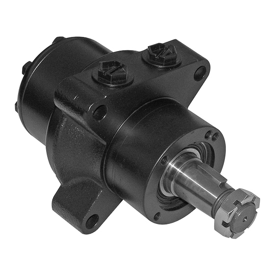
- Page 1 HGM-C LSHT Wheel Motor Service and Repair Manual BLN-52690 January 2018...
-
Page 2: Table Of Contents
End Cover........... 16 Service Position ........... 5 End Cover............ 6 Gearwheel Set ..........7 Cardan Shaft ..........7 Distributor Plate ........... 8 Output Shaft ..........8 Needle Bearing ..........9 Shaft Seal ............ 9 Check Valves ..........10 HGM-C LSHT Wheel Motor... -
Page 3: Foreword
This Service and Repair Manual is designed Distributor. Many distributors will be hosting to provide information useful in servicing and certification testing. These study guides will troubleshooting the Hydro-Gear HGM - C mo- cover most of the products and manufacturers tor. in our industry. -
Page 4: How To Use This Manual
How to Use This Manual How to Use This Manual General Description Each subassembly illustrated in this manual is Hydro-Gear HGM-C wheel motors convert illustrated with an exploded view showing the hydraulic energy (pressure and oil flow) into parts involved. The item reference numbers mechanical energy (torque and speed). -
Page 5: Tools
354 in-lbs [40 Nm] End Cover Bolt, 5/16-18 x .75 SHCS 180 - 240 in-lbs Brake Assembly [20.3 - 27.1 Nm] As a general rule, use the low end of the torque specification on fasteners when reassembling the unit. HGM-C LSHT Wheel Motor... -
Page 6: Drum & Brake Assemblies
5. Remove the brake assembly. See figure 2. the torque specification on fasteners when reassembling the unit. HGM Motor Drum Assembly Brake Assembly Cotter Pin Castellated Nut (1) Figure 1, Drum Assembly Bolt (29) Figure 2, Brake Assembly HGM-C LSHT Wheel Motor... -
Page 7: Service Position
(8), if installed. See figure 4. Drain oil from the motor. 4. Remove the retaining ring (2). See figure 5. 5. Place the HGM-C motor into a holding tool. See figure 6. Figure 5, Retaining Ring Figure 3, Identification Mark... -
Page 8: End Cover
See figure 8. Inspection 1. Inspect for wear or damage. 2. Inspect screws (22) – threads, for wear or damage. Figure 8, End Cover Screw (22) Figure 7, Screws HGM-C LSHT Wheel Motor... -
Page 9: Gearwheel Set
4. Dismantle the gearwheel set for inspection if contamination or damage is suspected. Inspection 1. Inspect for wear or damage. Cardan Shaft (15) O-ring (18) Gearwheel Set (17) Figure 10, Cardan Shaft Figure 9, Gearwheel Set HGM-C LSHT Wheel Motor... -
Page 10: Distributor Plate
(7). See figure 12. Inspection Inspection 1. Inspect for wear or damage. 1. Inspect for wear or damage. Distributor Plate (14) O-ring (13) Cardan Shaft (15) Figure 12, Output Shaft Figure 11, Distributor Plate HGM-C LSHT Wheel Motor... -
Page 11: Needle Bearing
(12) during dismantling and can be retrieved for re-use. 1. Inspect for wear or damage. Inspection 1. Inspect for wear or damage. Output Shaft (7) Ball Bearing (3) Housing (9) Figure 13, Output Shaft Seal Figure 14, Needle Bearing HGM-C LSHT Wheel Motor... -
Page 12: Check Valves
2. Remove the check valves (11) with a ground 3.5mm screw tap. See figure 15. The check valves are pressed in and can be removed by pulling on the tap. Inspection 1. Inspect for wear or damage. Check Valve (11) Figure 15, Check Valves HGM-C LSHT Wheel Motor... -
Page 13: Assembly
3. Place the ball bearing (3) onto output shaft (7) and press into position. See figure 3. Figure 2, Washer Bullet Pressing Tool Ball Bearing (3) Seal (5) Output Shaft (7) Output Shaft (7) Figure 1, Bullet/Output Shaft Seal Figure 3, Ball Bearing/Press Tool HGM-C LSHT Wheel Motor... -
Page 14: Check Valves
4. Seat the check valves (11) by lighty tapping Pressing Tool with a rubber hammer. See figure 5. Housing (9) Housing (9) Needle Bearing (12) Figure 4, Service Position Figure 6, Needle Bearing Check Valves (11) Figure 5, Check Valve HGM-C LSHT Wheel Motor... -
Page 15: Output Shaft
(9) and carefully lower into the motor housing (9). Press the output shaft with ball bearing, washer and seal into motor hous- Pressing Tool ing. See figure 9. Housing (9) Figure 9, Output Shaft/Press Tool Figure 7, Motor Housing HGM-C LSHT Wheel Motor... -
Page 16: Retaining Ring
5. Transfer marking from output shaft to car- dan shaft. See figure 12. Marking Cardan Shaft (15) Figure 10, Retaining Ring O-ring (13) Output Shaft Assembly Figure 12, Cardan Shaft Marks Housing (9) (Motor housing not shown) Figure 11, O-ring/Cardan Shaft HGM-C LSHT Wheel Motor... -
Page 17: Distributor Plate
See figure 14. to port surface. See figure 13. Distributor Plate (14) Indentations O-ring (18) Slots Gearwheel (17) O-ring (16) Housing (9) Figure 14, Gearwheel Set/O-ring Port Surface Figure 13, Distributor Plate HGM-C LSHT Wheel Motor... -
Page 18: End Cover
See figure 15. Alignment marks made before disassembly should line up. Gearwheel (17) Top of Tooth Mark Cardan Shaft (15) Figure 16, End Cover Washer (23) Screw (22) Figure 15, Gearwheel Set Figure 17, Washers & Screws HGM-C LSHT Wheel Motor... - Page 19 4. Refer to page 4 for brake/hub installation instructions. Plastic Plugs (8) Figure 18, Torque Sequence Woodruff Key (6) Castellated Nut (1) Figure 19, Final Assembly HGM-C LSHT Wheel Motor...
-
Page 20: Exploded View/ Parts List
Shaft Seal Woodruff Key Output Shaft Plastic Plugs Housing Check Valve 200 Seal Kit Needle Bearing O-ring Contained in seal kit Distributor plate Cardan Shaft O-ring Gearwheel set O-ring End Cover Label Screw Washer Seal Kit HGM-C LSHT Wheel Motor... -
Page 21: Notes
NOTES HGM-C LSHT Wheel Motor... - Page 22 NOTES HGM-C LSHT Wheel Motor...
- Page 24 © 2008 HYDRO-GEAR Printed in U.S.A. Rev. P4...
Need help?
Do you have a question about the HGM-C and is the answer not in the manual?
Questions and answers