
Related Manuals for FLIR Raymarine SiriusXM SR200


Summary of Contents for FLIR Raymarine SiriusXM SR200
- Page 1 SR200 SiriusXM InfoLINK Weather & Audio Receiver Installation instructions English (en-US) Date: 06-2019 Document number: 87320-3 © 2019 Raymarine UK Limited & Sirius XM Radio Inc.
- Page 2 MarineShield, Seahawk, Autohelm, Automagic, and Visionality are registered or claimed trademarks of Raymarine Belgium. FLIR, DownVision, SideVision, Dragonfly, Quantum, Instalert, Infrared Everywhere, and The World’s Sixth Sense are registered or claimed trademarks of FLIR Systems, Inc. All other trademarks, tradenames, or company names referenced herein are used for identification only and are the property of their respective owners.
-
Page 3: Software Updates
Software Updates Important: Check the Raymarine website for the latest software releases for your product, www.raymarine.com/software. Product Handbooks The latest versions of all English and translated handbooks are available to download in PDF format from the website www.raymarine.com. Please check the website to ensure you have the latest handbooks. Copyright ©2019 Raymarine UK Ltd. -
Page 4: General Information
case of SSB radios, the distance should be Caution: Power supply protection increased to 7 ft (2 m). When installing this product ensure the power source - More than 2 m (7 ft) from the path of a is adequately protected by means of a suitably-rated radar beam. -
Page 5: Product Disposal
Suppression Ferrites Warranty registration Raymarine cables may be fitted with suppression To register your Raymarine product ownership, ferrites. These are important for correct EMC please visit www.raymarine.com and register online. performance. If a ferrite has to be removed for any It is important that you register your product to purpose (e.g. -
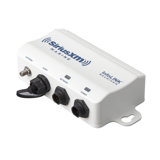
Page 6: Parts Supplied
Parts Supplied SiriusXM Receiver Raymarine MFD SiriusXM to Raymarine Network Cable InfoLINK R E C E I V E R M A R I N E ANTENNA AUDIO NETWORK POWER SiriusXM Stereo Audio Cable SiriusXM Marine InfoLINK™ Receiver SiriusXM Power Cable ®... -
Page 7: Installation Overview
Multifunction display hardware and software compatibility For compatibility information visit raymarine.com/weather. Installation Overview InfoLINK MULTIFUNCTION DISPLAY Shown at right is a typical installation RECEIVER overview for the InfoLINK Receiver in a ® Raymarine system. InfoLINK R E C E I V E R M A R I N E The InfoLINK Receiver can be ANTENNA... -
Page 8: Required Additional Components
Required Additional Components Required for Required for Component / Service SiriusXM Satellite Radio SiriusXM Marine Weather Sirius SRA-40 type-approved antenna Compatible Raymarine multifunction display GPS receiver — provides position information for your vessel in the weather, chart and radar applications. Some multifunction displays have an internal GPS receiver. -
Page 9: Cable Identification
Cable Identification The following is the pin identification for the Data Cable provided with the InfoLINK Receiver. SiriusXM Receiver Raymarine MFD SiriusXM Raymarine Description Description Connector Connector Ethernet RX+ (White/Green) Ethernet TX+(White/Orange) Ethernet RX– (Green) Ethernet TX– (Orange) Ethernet TX+(White/Orange) Not Used Ethernet TX–... - Page 10 RayNet to RayNet Cables for longer cable runs The following cables are available from Raymarine: • A80162: 100mm (3.9in) RayNet cable joiner (Male connectors at both ends; required for all extensions). • A80161: 400mm (1.3ft) RayNet (female to female) cable. • A62361: 2m (6.56ft) RayNet (female to female) cable. • A80005: 5m (16.4ft) RayNet (female to female) cable.
- Page 11 The following is the pin and wire identification for the Power Cable provided with the InfoLINK Receiver. Power Wire Description Description Connector Color Battery + (Switched) Battery + (Switched) Ground - Black Ground - RF Shield Ground White RF Shield Ground The following is the pin and connector identification for the Audio Cable provided with the InfoLINK Receiver.
- Page 12 InfoLINK Receiver Installation Connect the Power Cable The InfoLINK Receiver should be connected to a 12 Select a mounting location for the InfoLINK Receiver or 24 volt power source, negative ground. that is sheltered from the elements. While the Caution: Some vessels may have a positive ground receiver is water resistant, it should be mounted system.
- Page 13 • Cable must be of a suitable gauge for the Note: The suitable fuse rating for the thermal circuit load. breaker is dependent on the number of devices you are connecting. If in doubt consult an authorized • Each unit should have its own dedicated Raymarine dealer.
-
Page 14: Connect The Network Cable
Connect the Network Cable Connect the Audio Cable (optional) The Network Cable should be connected to your The audio connection is optional and is used if you Raymarine system. This cable has two different subscribe to a SiriusXM music and entertainment connectors - one end connects to the Raymarine package in addition to the SiriusXM Marine system and the other to the InfoLINK Receiver. -
Page 15: Antenna Installation
Antenna Installation Caution: When installing the antenna, do not cut or alter the antenna cable, or remove the cable connectors. Two considerations are necessary before installing the antenna. First, finding a suitable mounting location, and second determine how the antenna will be mounted. There are several in-box mounting options for the antenna, or accessories can be purchased from marine stores for additional mounting options. - Page 16 Choose a Mounting Option In-Box Mounting Options Surface Mount Antenna secured from the underside of the mounting surface. For mounting surfaces between 1/4” and 1” thick, use the supplied extension shaft. Route antenna cable through the mounting surface. Secure from below mounting surface using the mounting lock washer &...
- Page 17 Installing the Antenna Follow the instructions in the next sections for the mounting method you’ve selected. Do not cut the In-box antenna mounting options are surface mount, 6” antenna lead or remove the connectors from low-profile surface mount, or pedestal mount. any of the cables under any circumstances.
- Page 18 that was drilled. center hole for the antenna cable. When drilling fiberglass surfaces, use a small backup 4. Apply a small bead of marine sealant around block of scrap wood to control push-through the outer edge of the antenna base to insure a splintering.
- Page 19 5. Either pass the 6” antenna lead along with the connector through the center hole, or, lay the 6” antenna lead into the cable opening in the Antenna base gasket. Place the antenna, base, and base gasket on the mounting surface aligning it to Mounting Holes the marks made in step 3.
- Page 20 b. Align the base with the antenna, the base o-ring in place. gasket, and the pedestal top so that the 7. If you are not routing the 6” antenna lead openings for the 4 screws are aligned, and out through the side of the pedestal bottom, use the provided screws to screw them continue with step 9.
- Page 21 out through the side of the pedestal bottom, Rail Mount make sure the antenna lead can turn freely so The center hole in ratchet-type antenna mounts that it does not get twisted as you screw the will not accommodate the SRA-50’s connector. You antenna assembly onto the pedestal bottom.
-
Page 22: Verify Operation
Verify Operation Subscribe to SiriusXM Services Power on the Raymarine system, and the InfoLINK You can subscribe to the SiriusXM Marine service Receiver. Verify that the Power LED light is on and add satellite Radio at a discount by following (blue), and that the Network LED light is randomly these steps: flashing green, which indicates normal network... -
Page 23: Troubleshooting
Troubleshooting The troubleshooting information in this section is for general reference. Consult the documentation that accompanied your Raymarine system for specific operating instructions and advisory messages that may be displayed. LED Indicator Lights The InfoLINK Receiver has two LED indicator lights which show the current state of the receiver. Power LED Network LED Status... -
Page 24: Raymarine Customer Support
MFD Message Reason MFD Message Reason No Signal Make sure that the vessel is Channel Not The channel you have selected (NoSignal) outdoors with a clear view of the Subscribed (CH is not part of your current southern sky. Unsubscribed, subscription plan. -
Page 25: Specifications
Specifications FCC Statement The user is cautioned that changes or modifications not expressly InfoLINK Receiver approved by Sirius XM Radio Inc. can void the user’s authority to operate this device. This device complies with Part 15 of the FCC Rules. Operation is Dimensions . -
Page 26: Environmental Information
Copyrights and Trademarks Raymarine Legal Information Raymarine by FLIR and related marks are property of Raymarine UK Limited. All Rights Reserved. Shakespeare Legal Information Shakespeare and related marks are property of Shakespeare Company, LLC. All Rights Reserved. - Page 27 Important SiriusXM Legal Notice About Installation Installation instructions are provided for your convenience. You must determine if you have the knowledge, skills, and ability required to properly perform installation. Professional installation is recommended. SiriusXM shall have no liability for damage/injury resulting from the installation/use of any SiriusXM or other products. You must ensure that all products are installed in adherence with local laws and regulations and in such a manner as to allow a vehicle to be operated safely and without distraction.
- Page 28 Raymarine Inc. 9 Townsend West, Nashua, NH, 03063. United States. Tel: (+1) 603-324-7900 www.raymarine.com a brand by...
Need help?
Do you have a question about the Raymarine SiriusXM SR200 and is the answer not in the manual?
Questions and answers