
Subscribe to Our Youtube Channel
Related Manuals for FLIR Raymarine i70s


Summary of Contents for FLIR Raymarine i70s
- Page 1 i70s Instrument INSTALLATION & OPERATION INSTRUCTIONS English (EN) Date: 05-2016 Document number: 81364-1 © 2016 Raymarine UK Limited...
- Page 2 Printed Manuals Would you prefer a printed version of this document? Full documentation for your product is always provided as a free download on the Raymarine website, but some customers prefer manuals in a printed format. Raymarine provides a Print Shop service which enables you to purchase a printed manual (paperback book), delivered to your door.
- Page 3 Gear Up, Marine Shield, Seahawk, Autohelm, Automagic, and Visionality are registered or claimed trademarks of Raymarine Belgium. FLIR, DownVision, SideVision, Dragonfly, Quantum, Instalert, Infrared Everywhere, and The World’s Sixth Sense are registered or claimed trademarks of FLIR Systems, Inc. All other trademarks, trade names, or company names referenced herein are used for identification only and are the property of their respective owners.
-
Page 5: Table Of Contents
Contents Chapter 1 Important information......7 7.1 Transducer types ..........40 7.2 Depth calibration ..........40 TFT Displays ............... 7 7.3 Speed calibration ..........41 Water ingress .............. 7 7.4 Wind calibration ........... 46 Disclaimer ..............7 7.5 Rudder reference calibration ......... 48 EMC installation guidelines .......... - Page 6 18.1 Spares and Accessories ........100 18.2 Smart transducers ..........100 18.3 Instrument Depth, Speed and Temperature (DST) transducers ........... 101 18.4 Instrument Depth transducers ......102 18.5 Instrument Speed and Temperature transducers ............. 102 18.6 Instrument Wind Vane transducer...... 103 18.7 Instrument Rotavecta transducer.......
-
Page 7: Chapter 1 Important Information
Chapter 1: Important information Caution: Sun covers • If your product is supplied with a sun Warning: Product installation and cover, to protect against the damaging operation effects of ultraviolet (UV) light, always • This product must be installed and fit the sun cover when the product is operated in accordance with the not in use. -
Page 8: Emc Installation Guidelines
EMC installation guidelines Connections to other equipment Raymarine equipment and accessories conform to Requirement for ferrites on non-Raymarine cables the appropriate Electromagnetic Compatibility (EMC) If your Raymarine equipment is to be connected regulations, to minimize electromagnetic interference to other equipment using a cable not supplied by between equipment and minimize the effect such Raymarine, a suppression ferrite MUST always be interference could have on the performance of your... -
Page 9: Chapter 2 Document And Product Information
Chapter 2: Document and product information Chapter contents • 2.1 Document information on page 10 • 2.2 Product overview on page 10 Document and product information... -
Page 10: Document Information
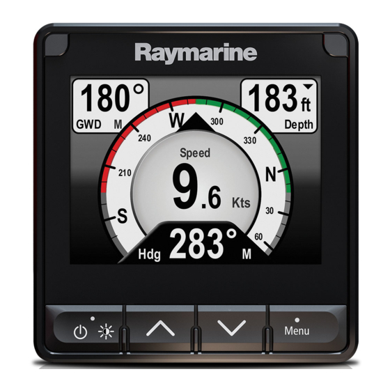
2.1 Document information 2.2 Product overview This document contains important information The i70s is a multifunctional instrument display related to the installation of your Raymarine product. with AIS capabilities. In conjunction with a compatible instrument transducers and an iTC-5, The document includes information to help you: the i70s provides a detailed view of environmental, •... -
Page 11: Chapter 3 Planning The Installation
Chapter 3: Planning the installation Chapter contents • 3.1 Installation checklist on page 12 • 3.2 Parts supplied on page 12 • 3.3 Compatible transducers on page 13 • 3.4 Software updates on page 13 • 3.5 Tools on page 14 •... -
Page 12: Installation Checklist
3.1 Installation checklist 3.2 Parts supplied Installation includes the following activities: The following parts are supplied with your product. Installation Task Plan your system. Obtain all required equipment and tools. Site all equipment. Route all cables. Drill cable and mounting holes. Make all connections into equipment. -
Page 13: Compatible Transducers
3.3 Compatible transducers 3.4 Software updates For a list of compatible transducers please refer to The software running on the product can be updated. Chapter 18 Options and accessories. • Raymarine periodically releases software updates to improve product performance and add new features. -
Page 14: Tools
3.5 Tools 3.6 Typical systems The following illustrations show the products that can Tools required for installation be connected in a typical system. Example: Simple environmental data system 12 V dc D12055-1 D13420-1 Power drill Item Description Jig saw Instrument display (e.g. i70s) Screwdriver SeaTalk ng®... - Page 15 Example: Expanded system without autopilot LIFETAG 12 V / 24 V SeaT alk ng SeaT alk ng 12 V dc SeaT alk ng D13421-1 Item Description AIS receiver / transceiver (AIS350 / AIS650) Instrument display (e.g. i70s) LifeTag — Man Over Board (MOB) system SeaTalk ng®...
- Page 16 Example: Expanded system with autopilot LIFETAG 12 V / 24 V SeaT alk ng SeaT alk ng SeaT alk ng 12 V dc / 24 V dc D13422-1 Item Description AIS receiver / transceiver (AIS350 / AIS650) Instrument display (e.g. i70s) LifeTag —...
-
Page 17: System Protocols
3.7 System protocols 3.8 Warnings and cautions Your product can be connected to various products Important: Before proceeding, ensure that you and systems to share information and so improve have read and understood the warnings and the functionality of the overall system. These cautions provided in the Chapter 1 Important connections may be made using a number of... -
Page 18: General Location Requirements
3.9 General location requirements Viewing angle considerations As display contrast, color and night mode Important considerations when choosing a suitable performance are all affected by the viewing angle, location for your product. Raymarine recommends you temporarily power up This product is suitable for mounting above or below the display when planning the installation, to enable decks. -
Page 19: Product Dimensions
3.10 Product dimensions 14.05 mm 110 mm (4.33 in) 90 mm (0.55 in) 29.8 mm (3.54 in) (1.17 in) D13423-1 Planning the installation... - Page 20 i70s Installation and operation instructions...
-
Page 21: Chapter 4 Cables And Connections
Chapter 4: Cables and connections Chapter contents • 4.1 General cabling guidance on page 22 • 4.2 Connections overview on page 22 • 4.3 SeaTalk ng® power supply on page 23 • 4.4 Cable ferrite installation on page 25 • 4.5 SeaTalk ng®... -
Page 22: General Cabling Guidance
4.1 General cabling guidance 4.2 Connections overview Use the following information to help you identify the Cable types and length connections on your product. It is important to use cables of the appropriate type Connector Connects to: Suitable cables and length SeaTalk SeaTalk •... -
Page 23: Seatalk Ng® Power Supply
4.3 SeaTalk ng® power supply In-line fuse and thermal breaker ratings The SeaTalk ng® network’s power supply requires an Power is supplied to the product over the SeaTalk in-line fuse or thermal breaker to be fitted. backbone. In-line fuse rating Thermal breaker rating A SeaTalk backbone requires one 12 V dc power... - Page 24 • You MUST fit a suitably rated fuse or breaker • If you need to extend the length of the power between the red wire and the battery’s positive cable, ensure you use suitably rated cable and terminal. that sufficient power (12 V dc) is available at the SeaTalk ng®...
-
Page 25: Cable Ferrite Installation
4.4 Cable ferrite installation 4.5 SeaTalk ng® connection Your product is supplied with a cable ferrite. To The unit connects as part of a SeaTalk network. ensure EMC Compliance, the supplied ferrite must Example: SeaTalk ng®® system with Evolution be fitted to the cable according to the following autopilot and iTC-5 instructions. -
Page 26: Nmea 2000 Connection
4.6 NMEA 2000 connection Example: SeaTalk ng® system with SPX SmartPilot and transducer pods You can: • use your SeaTalk ng® backbone and connect NMEA 2000 devices using a spur, or SMART • connect the unit to a DeviceNet spur into an existing NMEA 2000 backbone. -
Page 27: Seatalk Connection
4.7 SeaTalk connection 4.8 Transducer connections Connections to an existing SeaTalk system must be iTC-5 connection made using a SeaTalk to SeaTalk ng® adaptor cable. For details on connecting an iTC-5 to the SeaTalk ng® backbone and connecting transducers to the iTC-5, Basic SeaTalk system example refer to the documentation provided with your iTC-5. - Page 28 i70s Installation and operation instructions...
-
Page 29: Chapter 5 Mounting
Chapter 5: Mounting Chapter contents • 5.1 Bezel removal on page 30 • 5.2 Removing the keypad on page 30 • 5.3 Mounting on page 31 Mounting... -
Page 30: Bezel Removal
5.1 Bezel removal 5.2 Removing the keypad To remove the keypad from the unit follow the steps below. • Care Point — Take care not to bend the keypad as this may prevent the keypad from fitting correctly. D13430-1 1. Remove the Front bezel. 2. -
Page 31: Mounting
5.3 Mounting Note: The supplied gasket provides a seal between the unit and a suitably flat and stiff Pre-mounting check mounting surface or binnacle. The gasket should be used in all installations. It may also be The product is designed to be surface mounted. necessary to use a marine-grade sealant if the Before mounting the unit, ensure you have: mounting surface or binnacle is not entirely flat and... - Page 32 i70s Installation and operation instructions...
-
Page 33: Chapter 6 Getting Started
Chapter 6: Getting started Chapter contents • 6.1 Controls on page 34 • 6.2 Power on page 34 • 6.3 Completing the startup wizard on page 35 • 6.4 Display settings on page 35 • 6.5 Multiple data sources (MDS) overview on page 37 •... -
Page 34: Controls
6.1 Controls 6.2 Power Button Name Function Powering on the unit Power Power on, The unit will automatically turn on with the system, Power off, Open unless it has previously been powered off using the brightness menu, Power button. Cancel, Back With the unit powered off: Move up, Increase 1. -
Page 35: Completing The Startup Wizard
6.3 Completing the startup wizard 6.4 Display settings When you power-up the unit for the first time or after Adjusting the unit’s brightness a system reset the Startup Wizard is displayed. To adjust the unit’s LCD brightness level, when it The setup wizard guides your through the following is not part of a Shared Brightness group follow the basic configuration settings:... - Page 36 Display response 1. Select the Network Group that you want to assign the unit to. Setting the Display Response A list of network groups will be displayed: Setting the Display Response to a low value will • None (default) dampen data fluctuations to provide a more stable •...
-
Page 37: Multiple Data Sources (Mds) Overview
6.5 Multiple data sources (MDS) 3. Select your preferred data source, or overview 4. Select Auto to allow the system to decide. ACTIVE is displayed next to the data source that When a system includes multiple instances of a is the current source for the data type. data source the preferred data source is selected automatically. -
Page 38: Quick Options Menu
6.6 Quick Options menu The Quick Options menu (Menu > Quick Options) is a dynamic menu that displays menu items relative to the data displayed on the current Favorite page or Quick View page being viewed. Quick options menu items Depending on the page being displayed different quick options are available as follows: Page displayed... -
Page 39: Chapter 7 Transducer Calibration
Chapter 7: Transducer calibration Chapter contents • 7.1 Transducer types on page 40 • 7.2 Depth calibration on page 40 • 7.3 Speed calibration on page 41 • 7.4 Wind calibration on page 46 • 7.5 Rudder reference calibration on page 48 •... -
Page 40: Transducer Types
7.1 Transducer types 7.2 Depth calibration The transducers listed in the table below can be Depth Offset calibrated using the display. Depths are measured from the transducer to the Transducer type Connection bottom, you can apply an offset value to the depth data, so that the displayed depth reading represents Depth transducers connected via iTC-5 or Depth... -
Page 41: Speed Calibration
7.3 Speed calibration 9. Select the location that you want depth measurements to be taken from. Speed transducer calibration is required as After selection the Depth Offset page is displayed. transducer performance is affected by a number of If you have selected Waterline or Keel a Depth variables such as transducer location, shape of the Offset must be applied. - Page 42 1 Point Speed Calibration Nautical measured mile markers For most installations a 1 Point Speed Calibration is When neither SOG data or any other reliable means all that is required. of estimating Speed Through the Water (STW) is available, Nautical Measured Mile Markers can Prerequisites: be used to help calibrate Log Speed.
- Page 43 3. End point (stop stopwatch) 4. First pair of markers 0 kts 50 kts 5. Second pair of markers To provide a more accurate reading the vessel should make between 4 to 6 runs in both directions to allow for tide and wind conditions. The average of the time taken over all runs should be used to calculate Log Speed.
- Page 44 • The current speed value in knots Note: * Step only applicable to iTC-5. • The time in minutes it takes to cover the 7. Select Speed Calibration. measured distance 8. Select Advanced. 2. Calculate the actual speed over the measured 9.
- Page 45 13. Repeat steps 7 to 11 for each Calibration Point From the Advanced Menu: you want to add. 1. Select Enter new cal table. 2. Select Start. The more Calibration Points the higher the accuracy of Log Speed. All existing Calibration Points are deleted and you will be prompted to enter new Calibration Points.
-
Page 46: Wind Calibration
7.4 Wind calibration • Conditions should be calm (i.e. a slight sea) and a steady breeze. Try to ensure the vessel is not rolling or pitching too much. Calibrating wind • You will need to be underway, with sufficient space From the list of transducers found: to turn in a large slow circle unhindered. - Page 47 Note: * Step only applicable to iTC-5. 4. Select Wind Xdcr Adjust. 4. Use the Up and Down buttons to adjust the Calibration Factor until the AWS reading matches your referenced source of AWS. 5. Use the Up and Down buttons to adjust the offset value so that the reported AWA is 0 degrees.
-
Page 48: Rudder Reference Calibration
7.5 Rudder reference calibration 10. Select Back to return to the Rudder Calibration Menu. You can calibrate a rudder reference transducer that is connected to an iTC-5. Adjusting the Rudder Angle The rudder reference transducer must be connected You can manually adjust the Rudder Angle. to the rudder reference connection of the iTC-5 Manual adjustment of the Rudder Angle requires a . -
Page 49: Compass Calibration
7.6 Compass calibration metal items or items that may cause interference, then repeat the calibration process. If you still You can calibrate a Fluxgate Compass that is find a deviation of more than 15 degrees, contact connected to an iTC-5. your Raymarine dealer for advice. - Page 50 i70s Installation and operation instructions...
-
Page 51: Chapter 8: Favorite Pages
Chapter 8: Favorite Pages Chapter contents • 8.1 Favorite pages on page 52 • 8.2 Customizing pages on page 52 Favorite Pages... -
Page 52: Favorite
8.1 Favorite pages 8.2 Customizing pages Favorite pages can be customized from the The unit displays data on Favorite pages. The Favorites page menu. You can: Favorite pages displayed are dependent on the Boat Type selected during the Startup Wizard. •... - Page 53 3. Select the required layout. 4. Select a cell. 5. Browse the Data Categories list and select the Data item that you want to display in the selected cell. 6. Complete steps 2 and 3 for all remaining cells. 7. When finished highlight the onscreen tick and select Save.
- Page 54 i70s Installation and operation instructions...
-
Page 55: Chapter 9 Data (Quick View)
Chapter 9: Data (Quick View) Chapter contents • 9.1 Data items on page 56 • 9.2 Viewing Data (Quick View) on page 58 • 9.3 Adding a Quick View as a Favorite page on page 59 Data (Quick View) -
Page 56: Data Items
9.1 Data items Favorite Page Quick View (Data Data Category (Data Items) Items) The table below shows a list of possible data items available to display on Favorite Pages and using • 1 Engine • 1 Engine the Data (Quick View) menu. Overview Overview Note: The data described in the table below is... - Page 57 Favorite Page Quick View (Data Favorite Page Quick View (Data Data Category (Data Items) Items) Data Category (Data Items) Items) • SOG • COG Navigation • Active Waypoint • Active Waypoint Name Name • SOG History • COG History • Waypoint ID •...
-
Page 58: Viewing Data (Quick View)
9.2 Viewing Data (Quick View) Favorite Page Quick View (Data Data Category (Data Items) Items) You can use the Data (Quick View) menu to Time • Local Time • Clock view data that may not be available on the current Favorite Pages. -
Page 59: Adding A Quick View As A Favorite Page
9.3 Adding a Quick View as a Favorite page The Quick View data pages can be added as a Favorite page. From the Data (Quick View) menu: 1. Select the Data item so that it is displayed onscreen. 2. Press the Menu button. 3. - Page 60 i70s Installation and operation instructions...
-
Page 61: Chapter 10 Ais
Chapter 10: AIS Chapter contents • 10.1 AIS Overview on page 62 • 10.2 AIS target symbols on page 63 • 10.3 Setting AIS Range on page 64 • 10.4 Viewing AIS target information on page 64 • 10.5 Enabling and disabling AIS Silent mode on page 65... -
Page 62: Ais Overview
10.1 AIS Overview AIS Messages AIS Messages Description When an AIS receiver/transceiver is connected to your system, the AIS feature enables you to AIS off AIS Unit off receive information broadcast by other AIS equipped (none) AIS is on and transmitting vessels, and to view these vessels as targets relative to your boat. -
Page 63: Ais Target Symbols
10.2 AIS target symbols Target type Description Symbol Aid To Navigation AToN target is Your display shows a range of symbols to represent (AToN) target OFF position & the different types of AIS target. (Virtual) lost. Target black Target type Description Symbol with red cross and... -
Page 64: Setting Ais Range
10.3 Setting AIS Range 10.4 Viewing AIS target information The distance displayed on the AIS page can be You can view information about AIS targets. adjusted. With the AIS page displayed: 1. Press the Menu button. With the AIS page displayed: 2. -
Page 65: Enabling And Disabling Ais Silent Mode
10.5 Enabling and disabling AIS Silent mode AIS silent mode enables you to disable the transmitting functions of your AIS equipment. This is useful when you do not want to transmit your vessel’s AIS data to other AIS receivers, but still wish to receive data from other vessels. - Page 66 i70s Installation and operation instructions...
-
Page 67: Chapter 11 Race Timer Settings
Chapter 11: Race timer settings Chapter contents • 11.1 Setting the Race Timer on page 68 • 11.2 Using the Race Timer on page 68 Race timer settings... -
Page 68: Setting The Race Timer
11.1 Setting the Race Timer 11.2 Using the Race Timer The Race Timer is used to show the time elapsed With the Race Timer page displayed: since the start of a race. The Race Timer has 3 1. Select Start. countdown timers. -
Page 69: Chapter 12 Instrument Alarms
Chapter 12: Instrument alarms Chapter contents • 12.1 Alarms on page 70 Instrument alarms... -
Page 70: Alarms
12.1 Alarms Alarm settings Most alarms are generated locally using specified Alarms are used to alert you to a situation or hazard thresholds. They are also transmitted to the requiring your attention. SeaTalk and SeaTalk networks for display at other Some examples of alarms are: compatible devices. - Page 71 Category Alarm Content Category Alarm Content Temperature Sea Temp. Alarm • On Wind TWS Low Alarm • On High True Wind • Off (de- • Off (de- Speed low fault) fault) Adjust • 0 — 50ºC Adjust • 0 — 200 •...
- Page 72 Category Alarm Content Other AIS Alarm Safety • On messages • Off (de- fault) Dangerous • On target • Off (de- fault) Safe zone • (0.1 , 0.2, 0.5, 1.0, 2.0) nm • (0.1 , 0.2, 0.5, 1.0, 2.0) sm •...
-
Page 73: Chapter 13 Setup Menu
Chapter 13: Setup menu Chapter contents • 13.1 Setup menu on page 74 Setup menu... -
Page 74: Setup Menu
13.1 Setup menu The Set-up menu provides settings to configure the unit. Menu item Description Options Transducer Set up and List of connected, Set-up calibrate compatible transducers transducers. as detailed in Transducer calibration section above. User Preferences Configure User • Time & Date Preferences. - Page 75 Transducer setup menu The Transducer Set-up menu enables calibration of connected transducers. Menu item Description Options iTC-5 Enables setup and calibration of transducers • Depth connected using an iTC-5. • Speed • Wind • Rudder reference • Compass Depth Enables setup and calibration of depth Details displays can supply information about transducers and provides the following options: the installed transducer or interface such as...
- Page 76 Menu item Description Options Speed calibration: • Add — adds a new speed setting using current SOG reading. • Edit — edits a speed setting in 0.1 kt increments. • Delete — deletes the selected speed setting. • Reset — resets speed calibration to default settings.
- Page 77 User Preferences menu The User Preferences menu enables you to customize the unit settings. Menu item Description Options Time & Date These options enable you to customize the date Date format: and time format to your requirements. You can • mm/dd/yy also specify a local time offset from Universal Time Constant (UTC), to compensate for any •...
- Page 78 Menu item Description Options Language Determines the language that will be used for all • English (UK) on-screen text, labels, menus and options. • English (US) • Chinese • Croatian • Danish • Dutch • Finnish • French • German •...
- Page 79 Menu item Description Options • 6000 rpm • 7000 rpm • 8000 rpm • 9000 rpm • 10000 rpm RPM Red Zone • Auto (default) • Custom value Variation Enables you to turn on and off magnetic Variation mode: variation, specify slave source or adjust •...
- Page 80 System set-up menu The System set-up menu enables users to customize the following user settings: Menu item Description Options Network group Allows adding multiple units together in Predefined groups a group so that when the color scheme • None or brightness is changed on one unit the changes are applied to all units in the •...
- Page 81 Diagnostics menu You can access diagnostics details from the Diagnostics menu: (Menu > Set-up > Diagnostics). Menu item Description Options About display Allows you to view information about the display • Software version you are using: • Hardware version • Bootloader version •...
- Page 82 i70s Installation and operation instructions...
-
Page 83: Chapter 14 Maintenance
Chapter 14: Maintenance Chapter contents • 14.1 Service and maintenance on page 84 • 14.2 Routine equipment checks on page 84 • 14.3 Product cleaning on page 85 • 14.4 Cleaning the display case on page 85 • 14.5 Cleaning the display screen on page 86 •... -
Page 84: Service And Maintenance
14.1 Service and maintenance 14.2 Routine equipment checks This product contains no user serviceable Raymarine strongly recommends that you complete components. Please refer all maintenance a number of routine checks to ensure the correct and and repair to authorized Raymarine dealers. reliable operation of your equipment. -
Page 85: Product Cleaning
14.3 Product cleaning 14.4 Cleaning the display case Best cleaning practices. The display unit is a sealed unit and does not require regular cleaning. If it is necessary to clean the unit, When cleaning products: follow this basic procedure: • If your product includes a display screen, do NOT 1. -
Page 86: Cleaning The Display Screen
14.5 Cleaning the display screen 14.6 Cleaning the sun cover A coating is applied to the display screen. This The supplied sun cover features an adhesive surface. makes it water repellent, and prevents glare. To In certain conditions unwanted contaminants may avoid damaging this coating, follow this procedure: stick to this surface. -
Page 87: Chapter 15 System Checks And Troubleshooting
Chapter 15: System checks and troubleshooting Chapter contents • 15.1 Troubleshooting on page 88 • 15.2 Power up troubleshooting on page 89 • 15.3 System data troubleshooting on page 90 • 15.4 Miscellaneous troubleshooting on page 91 • 15.5 Performing a Factory Reset on page 92 System checks and troubleshooting... -
Page 88: Troubleshooting
15.1 Troubleshooting The troubleshooting information provides possible causes and corrective action required for common problems associated with marine electronics installations. All Raymarine products are, prior to packing and shipping, subjected to comprehensive test and quality assurance programs. However, if you experience problems with the operation of your product this section will help you to diagnose and correct problems in order to restore normal... -
Page 89: Power Up Troubleshooting
15.2 Power up troubleshooting Problems at power up and their possible causes and solutions are described here. Product does not turn on or keeps turning off Possible causes Possible solutions Blown fuse / tripped breaker Check condition of relevant fuses and breakers and connections, replace if necessary (Refer to the Technical Specification section of your product’s installation instructions for fuse ratings.) If fuse keeps blowing check for cable damage, broken connector pins or... -
Page 90: System Data Troubleshooting
15.3 System data troubleshooting Aspects of the installation can cause problems with the data shared between connected equipment. Such problems, their possible causes and solutions are described here. Problem Possible causes Possible solutions Instrument, engine or other Data is not being received at the Check the data bus (e.g. -
Page 91: Miscellaneous Troubleshooting
15.4 Miscellaneous troubleshooting Miscellaneous problems and their possible causes and solutions are described here. Problem Possible causes Possible solutions Display behaves erratically: Intermittent problem with power Check relevant fuses and breakers. to the display. Check that the power supply cable is sound and that all •... -
Page 92: Performing A Factory Reset
15.5 Performing a Factory Reset To reset your unit to factory default settings follow the steps below. Note: Performing a factory reset will erase all saved data and customized settings. 1. Press the Menu button. 2. Select Set Up. 3. Select Factory Reset. 4. -
Page 93: Chapter 16 Technical Support
Chapter 16: Technical support Chapter contents • 16.1 Raymarine product support and servicing on page 94 • 16.2 Viewing product information on page 95 Technical support... -
Page 94: Raymarine Product Support And Servicing
246 932 164 64 (Raymarine subsidiary) Asia Pacific Russia +7 495 info@mikstmarine.ru United States +1 (603) rm-usrepair@flir.com 788 0508 (Authorized Raymarine (US) 324 7900 distributor) Web support Please visit the “Support” area of the Raymarine website for: • Manuals and Documents —... -
Page 95: Viewing Product Information
16.2 Viewing product information 1. Press the Menu button. 2. Select Set-up. 3. Select Diagnostics. 4. Select About Display. A range of information is displayed, including the software version and Serial number. 5. Use the Up and Down buttons to cycle through the information. - Page 96 i70s Installation and operation instructions...
-
Page 97: Chapter 17 Technical Specification
Chapter 17: Technical specification Chapter contents • 17.1 Technical specification on page 98 Technical specification... -
Page 98: Technical Specification
17.1 Technical specification Nominal supply voltage 12 V dc Operating voltage range 9 V dc to 16 V dc (protected up to 32 V dc) Current 143 mA Power consumption 1.7 W LEN (Refer to the SeaTalk reference manual for further information.) Operating Temperature –20°C to 55°C (–4°F to... -
Page 99: Chapter 18 Options And Accessories
Chapter 18: Options and accessories Chapter contents • 18.1 Spares and Accessories on page 100 • 18.2 Smart transducers on page 100 • 18.3 Instrument Depth, Speed and Temperature (DST) transducers on page 101 • 18.4 Instrument Depth transducers on page 102 •... -
Page 100: Spares And Accessories
18.1 Spares and Accessories 18.2 Smart transducers Smart transducers can be connected directly to the Part number Description SeaTalk ng® backbone without the need for an iTC-5 A80353 Black bezel i70s / p70s / or transducer pod. p70Rs The smart transducers listed below are compatible A80354 Gunmetal bezel i70s / p70s /... -
Page 101: Instrument Depth, Speed And Temperature (Dst) Transducers
18.3 Instrument Depth, Speed and Part Temperature (DST) transducers number Image Mounting Type A22146 Thru-Hull DST800 The DST transducers listed below are compatible Bronze with the following instrument displays: • i40 Depth / i40 Speed / i40 Bidata • i50 Depth i50 Speed / i50 Tridata •... -
Page 102: Instrument Depth Transducers
18.4 Instrument Depth transducers 18.5 Instrument Speed and Temperature transducers The depth transducers listed below are compatible with the following instrument displays: The speed and temperature transducers listed below are compatible with the following instrument displays: • i40 Depth / i40 Bidata •... -
Page 103: Instrument Wind Vane Transducer
18.6 Instrument Wind Vane transducer 18.7 Instrument Rotavecta transducer The wind vane transducers listed below are The wind transducers listed below are compatible compatible with the following instrument displays: with the following instrument displays: • i60 Wind • i40 Wind •... -
Page 104: Other Transducers
18.8 Other transducers 18.9 SeaTalk ng® cables and accessories When connected using an iTC-5, the transducers listed below are compatible with the your i70 / i70s SeaTalk cables and accessories for use with display: compatible products. Part number Image Type Description Part No Notes... - Page 105 Description Part No Notes SeaTalk to bare A06044 ends 3 m (9.8 ft) spur SeaTalk Power A06049 cable SeaTalk A06031 Terminator A06028 Provides 1 x spur SeaTalk T-piece connection SeaTalk 5–way A06064 Provides 3 x spur connector connections SeaTalk A06030 backbone extender SeaTalk to E22158...
-
Page 106: Seatalk
18.10 SeaTalk cable kits SeaTalk starter kit (T70134) Quan- Parts included tity Connector A Cable Connector B Length Spur cable 3 m (9.8 ft) (A06040) Power cable 1 m (3.3 ft) (A06049) Backbone terminator (A06031) 5–way connector (A06064). Each connector block allows the connection of up to 3 compatible... - Page 107 Quan- Parts included tity Connector A Cable Connector B Length T-piece (A06028) Backbone terminator (A06031) SeaTalk Evolution cable kit (R70160) Quan- Parts included tity Connector A Cable Connector B Length Backbone cable 5 m (16.4 ft) ((A06036)) Power cable 1 m (3.3 ft) (A06049) Spur cable 1 m (3.3 ft)
- Page 108 Quan- Parts included tity Connector A Cable Connector B Length T-piece (A06028) Backbone terminator (A06031) SeaTalk converter kit (E22158) Quan- Parts included tity Connector A Cable Connector B Length Power cable 1 m (3.3 ft) (A06049) Backbone terminator (A06031) Blanking plug(A06032) SeaTalk (3 pin) 0.4 m (1.3 ft)
-
Page 109: Seatalk Accessories
18.11 SeaTalk accessories SeaTalk cables and accessories for use with compatible products. Description Part No Notes 3–way SeaTalk D244 junction box 1 m (3.28 ft) D284 SeaTalk extension cable 3 m (9.8 ft) SeaTalk D285 extension cable 5 m (16.4 ft) D286 SeaTalk extension cable... - Page 110 i70s Installation and operation instructions...
-
Page 111: Appendix A Supported Nmea 2000 Pgn List
Appendix A Supported NMEA 2000 Transmit- PGN list Description Received ● 129039 AIS Class B Position Transmit- Report Description Received ● 129040 AIS Class B ● ● 59392 Extended Position Acknowledgment Report ● 59904 ISO Request ● 129041 AIS Aids to ●... - Page 112 i70s Installation and operation instructions...
- Page 114 www.raymarine.com Raymarine UK Limited, Marine House, Cartwright Drive, Fareham, PO15 5RJ. United Kingdom. Tel: +44 (0)1329 246 700...
Need help?
Do you have a question about the Raymarine i70s and is the answer not in the manual?
Questions and answers