Table of Contents
Advertisement
Quick Links
Contents
1.0 INTRODUCTION .................................................................................................................................. 2
2.0 TESTING ................................................................................................................................................ 2
3.0 LIMITATIONS ...................................................................................................................................... 2
4.0 GLOSSARY ............................................................................................................................................ 2
5.0 SUMMARY OF OPERATION ............................................................................................................. 2
6.0 TELEPHONY CONTROL DIAGRAM ............................................................................................... 2
7.0 LED AND LCD KEYPAD MODEL ..................................................................................................... 2
8.0 LED KEYPAD ........................................................................................................................................ 2
8.1 UNDERSTAND YOUR KEYPAD INDICATORS .................................................................. 2
8.2 USER PROGRAMMING SUMMARY DIAGRAM ................................................................ 2
8.3 USER PROGRAMMING SUMMARY TABLE ....................................................................... 2
8.4 ARMING THE SYSTEM .......................................................................................................... 2
8.4.1 AWAY ARMING .................................................................................................................... 2
8.4.2 DAY ARMING....................................................................................................................... 2
8.4.3 NIGHT ARMING .................................................................................................................. 2
8.4.4 FORCE ARMING ................................................................................................................. 2
8.4.5 HOLIDAY ARMING ............................................................................................................. 2
8.4.6 AUTO TIMER ARMING ....................................................................................................... 2
8.4.7 TELEPHONE REMOTE ARMING ....................................................................................... 2
8.4.8 REMOTE CONTROL ARMING (OPTIONAL) ..................................................................... 2
8.5 DISARMING THE SYSTEM ................................................................................................... 2
8.5.1 KEYPAD DISARMING ......................................................................................................... 2
8.5.2 AUTO TIMER DISARMING ................................................................................................. 2
8.5.3 TELEPHONE REMOTE DISARMING ................................................................................. 2
8.5.4 REMOTE CONTROL DISARMING (OPTIONAL) ............................................................... 2
8.6 TURN ON/OFF HOME AUTOMATION POINT .................................................................... 2
8.7 BYPASS ZONE ......................................................................................................................... 2
8.8 UN-BYPASS ZONE .................................................................................................................. 2
8.9 VIEW SYSTEM TROUBLE ..................................................................................................... 2
8.10 VIEW ALARM MEMORY ..................................................................................................... 2
8.11 CHIME MODE ........................................................................................................................ 2
8.12 EMERGENCY SITUATION .................................................................................................. 2
8.13 PARTITIONING THE SYSTEM ............................................................................................ 2
8.14 ARMING A PARTITIONED SYSTEM ................................................................................. 2
8.14.1 AWAY ARMING 2 PARTITIONS SIMULTANEOUSLY ...................................................... 2
8.14.2 AWAY ARMING EITHER 1 PARTITION ........................................................................... 2
8.14.3 FASTKEY AWAY ARMING EITHER 1 PARTITION .......................................................... 2
8.14.4 PARTITION DAY ARMING ................................................................................................ 2
8.14.5 PARTITION NIGHT ARMING ........................................................................................... 2
8.14.6 PARTITION FORCE ARMING........................................................................................... 2
8.14.7 PARTITION HOLIDAY ARMING ....................................................................................... 2
SmartBus P900-TI6N USER MANUAL
1
V1.1
Advertisement
Table of Contents

Related Manuals for BLUGUARD SmartBus P900-TI6N


Summary of Contents for BLUGUARD SmartBus P900-TI6N
-
Page 1: Table Of Contents
SmartBus P900-TI6N USER MANUAL Contents 1.0 INTRODUCTION ..........................2 2.0 TESTING ..............................2 3.0 LIMITATIONS ............................2 4.0 GLOSSARY ............................2 5.0 SUMMARY OF OPERATION ......................2 6.0 TELEPHONY CONTROL DIAGRAM ....................2 7.0 LED AND LCD KEYPAD MODEL ..................... 2 8.0 LED KEYPAD ............................ - Page 2 SmartBus P900-TI6N USER MANUAL 8.15 PARTITION DISARMING ..................... 2 8.16 USER CODE ........................... 2 8.17 USER PROGRAMMING MODE ................... 2 8.17.1 ACCESS USER PROGRAMMING MODE ................. 2 8.17.2 EXIT USER PROGRAMMING MODE ................2 8.17.3 PROGRAM NEW AND CHANGING EXISTING MASTER / USER CODE ......2 8.17.4 PROGRAM NEW AND CHANGING EXISTING DURESS CODE ........
- Page 3 SmartBus P900-TI6N USER MANUAL 9.8 UN-BYPASS ZONE ........................2 9.9 VIEW SYSTEM TROUBLE ..................... 2 9.10 VIEW ALARM MEMORY ..................... 2 9.11 CHIME MODE ........................2 9.12 VIEW ZONE VOCABULARY SETTING ................2 9.13 VIEW HA POINT VOCABULARY SETTING ..............2 9.14 EVENT VIEWER ........................
- Page 4 SmartBus P900-TI6N USER MANUAL 9.20.5 BATTERY TEST ........................2 9.21 SYSTEM INFORMATION ......................... 2 9.22 SYSTEM SETTING..........................2 V1.1...
-
Page 5: Introduction
3.0 LIMITATIONS Even though BLUGUARD is an advanced security system, it does not 100% guarantee the protection against burglary, fire or other loses. Any alarm system whether commercial or residential is subjected to compromise or failure-to-warn for a variety of reasons. -
Page 6: Glossary
SmartBus P900-TI6N USER MANUAL 4.0 GLOSSARY Alarm Memory This is the history of the most recent violations that occurred the last time when an alarm was triggered. To set the system into the ARMED mode. In this mode, a zone violation will activate an alarm condition. -
Page 7: Summary Of Operation
SmartBus P900-TI6N USER MANUAL 5.0 SUMMARY OF OPERATION Intelligent Disarm [4-digit User Code] + [#] Intelligent Arming [4-digit User Code] + [#] Away Arm Hold down [1] for 2 seconds Day Arm Hold down [2] for 2 seconds Hold down [3] for 2 seconds... - Page 8 SmartBus P900-TI6N USER MANUAL SUMMARY OF OPERATION (CONT.) PARTITION SYSTEM ENABLED Intelligent Disarm [4-digit User Code] + [#] + [Partition 1] or [Partition 2] Intelligent Arming [4-digit User Code] + [#] + [Partition 1] or [Partition 2] Away Arm Hold down [1] for 2 seconds + [Partition 1] or [Partition 2]...
-
Page 9: Telephony Control Diagram
SmartBus P900-TI6N USER MANUAL 6.0 TELEPHONY CONTROL DIAGRAM Call In to System: Dial Wait for [Master System 1. System Voice Report Phone Answer Code] + welcome note and Number voice menu - Alarm triggered zone - System Arm / Disarm... -
Page 10: Led And Lcd Keypad Model
SmartBus P900-TI6N USER MANUAL 7.0 LED AND LCD KEYPAD MODEL PAGE 11 PAGE 44 V1.1... -
Page 11: Led Keypad
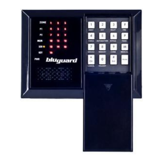
SmartBus P900-TI6N USER MANUAL 8.0 LED KEYPAD KEYPAD V1.1... -
Page 12: Understand Your Keypad Indicators
SmartBus P900-TI6N USER MANUAL 8.1 UNDERSTAND YOUR KEYPAD INDICATORS ZONE INDICATORS ARMED INDICATOR 1 AWAY ARM 2 DAY ARM 4 FORCE ARM (Red) (Red) This key will activate This key will activate This key will activate Indicate the status of... -
Page 13: User Programming Summary Diagram
SmartBus P900-TI6N USER MANUAL 8.2 USER PROGRAMMING SUMMARY DIAGRAM PROGRAM CODES MASTER CODE ENTER USER PROGRAMMING Press [01] + [New Code] + [Re-enter New Code] + [#] MODE ] + [MODE] + USER CODE [Master Code] + [#] Press [02 - 15] + [New Code] + [Re-enter New Code] + [#] Correct code or step –... -
Page 14: User Programming Summary Table
SmartBus P900-TI6N USER MANUAL 8.3 USER PROGRAMMING SUMMARY TABLE Access User Programming ] + [MODE] + [4-digit Master Code] + [#] Mode Exit User Programming Mode [MODE] + [#] Program New or Change Existing [01] + [New Master Code] + [Re-enter New Master Code] +... - Page 15 SmartBus P900-TI6N USER MANUAL USER PROGRAMMING SUMMARY TABLE (CONT.) Program System Timer System Clock [17] + [Current Time in 24-hour Format] + [#] Program Security Timers Partition 1 Auto Arm Timer [18] + [Partition 1 Security Auto ARM Timer] + [#]...
- Page 16 SmartBus P900-TI6N USER MANUAL Program GSM Personal [35] + [GSM Personal Telephone Number 2] + [#] Telephone Number 2 Program GSM Personal [36] + [GSM Personal Telephone Number 3] + [#] Telephone Number 3 Program GSM Personal [37] + [GSM Personal Telephone Number 4] + [#] Telephone Number 4 Remark: Button “P”...
-
Page 17: Arming The System
SmartBus P900-TI6N USER MANUAL 8.4 ARMING THE SYSTEM There are various options for arming the system Partition Arming Away Arming Day Arming Night Arming Force Arming Holiday Arming Remote Control Arming Timer Auto Arming Telephone Remote Arming For information on how to ARM Partition system, please refer to PARTITIONING THE SYSTEM at page 28 (Section 8.13). - Page 18 SmartBus P900-TI6N USER MANUAL 8.4.2 DAY ARMING (Press and hold down for 2 seconds) 1. This arming mode is ideal for DAY time arming with user still remains in the protected premises. 2. In this mode, the system will be armed instantly with certain preprogrammed, DAY STAY zones bypassed automatically.
- Page 19 SmartBus P900-TI6N USER MANUAL 9. There is no ENTRY delay in this arming mode. Any violation on the active zones will trigger the system instantly. 8.4.4 FORCE ARMING (Press and hold down for 2 seconds) 1. In this mode, the system will be armed with EXIT delay time which allows certain violated zones to be bypassed temporary.
-
Page 20: Auto Timer Arming
SmartBus P900-TI6N USER MANUAL 8.4.6 AUTO TIMER ARMING 1. Your system can be programmed to automatically ARM itself according to a programmed schedule. 2. This arming mode will automatically turn to FORCE ARM mode when the system timer reaches the preset AUTO ARM time. -
Page 21: Auto Timer Disarming
SmartBus P900-TI6N USER MANUAL e. Telephone Remote Disarm For information on how to DISARM Partition system, please refer to PARTITION DISARMING at page 34 (Section 8.15). 8.5.1 KEYPAD DISARMING [USER CODE] + [#] 1. To disarm the system, enter a valid 4-digit [USER CODE] followed by [#] key before expiry of the entry delay time. -
Page 22: Telephone Remote Disarming
SmartBus P900-TI6N USER MANUAL 8.5.3 TELEPHONE REMOTE DISARMING 1. Your system can be remotely DISARM from outside the house through any normal DTMF telephone or GSM hand phone. 2. This disarming mode will automatically turn off the security system when the user enters a correct Master Code through Telephone or hand phone. -
Page 23: Bypass Zone
SmartBus P900-TI6N USER MANUAL 8.7 BYPASS ZONE + [ZONE NUMBERS] + [#] (Press and hold down for 2 seconds) (1 to 16) 1. Press and hold down key [6] for 2 seconds. 2. The P1 and KEYLOCK indicators will slow flash and keypad audible indicator will sound 2 beeps. -
Page 24: View System Trouble
SmartBus P900-TI6N USER MANUAL 3. Press the zone number corresponding to the current bypassed zone e.g. press [2] if you wish to un-bypass zone 2. 4. To enter zone number more than 9, press button [F] to represent the ten’s digit. -
Page 25: View Alarm Memory
SmartBus P900-TI6N USER MANUAL 6. Press [#] key to exit and keypad audible indicator will sound 2 beeps. ZONE 1 indicator AC Loss ZONE 2 indicator Real Time Clock Loss (Program System Timer - refer to page 38) ZONE 3 indicator... -
Page 26: Emergency Situation
SmartBus P900-TI6N USER MANUAL 3. Press the key corresponding to the zone that you wish to be the chime zone. 4. To enter zone number more than 9, press button [F] to represent the ten’s digit. 5. E.g. To enter zone number 12, press [F] + [2], zone number 16 press [F] + [6]. - Page 27 SmartBus P900-TI6N USER MANUAL 3. The PANIC ALARM condition can also be activated by any FIXED or REMOTE PANIC button that has been installed. 4. If the panic button is set as silent zone, then the PANIC REPORTING CODE will be transmitted to the central monitoring station without the siren sounding.
-
Page 28: Partitioning The System
SmartBus P900-TI6N USER MANUAL 8.13 PARTITIONING THE SYSTEM Depending on your needs, your installer can program your control panel to recognize and control 2 separate areas (Partition 1 and Partition 2) by activating the system’s partitioning feature. User codes can also be programmed to ARM/DISARM one partition or both partitions simultaneously. -
Page 29: Away Arming Either 1 Partition
SmartBus P900-TI6N USER MANUAL 7. The keypad audible indicator will sound on and off for the duration of the EXIT delay. 8. Any bypassed zones will be shown by the flashing zone indicators. 9. Leave the premises only via the EXIT/ENTRY zone. - Page 30 SmartBus P900-TI6N USER MANUAL 6. The P1 indicator will illuminate if Partition 1 is armed. 7. The P2 indicator will illuminate if Partition 2 is armed. 8. The keypad audible indicator will sound on and off for the duration of the EXIT delay. Any bypassed zones will be shown by the flashing zone indicators.
-
Page 31: Fastkey Away Arming Either 1 Partition
SmartBus P900-TI6N USER MANUAL 9. User will be given an ENTRY delay time to disarm the system when enter the protected premises via ENTRY/EXIT zone. 8.14.3 FASTKEY AWAY ARMING EITHER 1 PARTITION [1 or 2] + [#] (Press and hold down for 2 seconds) 1. -
Page 32: Partition Night Arming
SmartBus P900-TI6N USER MANUAL 3. Ensure that all zone indicators are distinguished; if not, check that all protected premises are closed. 4. DO NOT open the ENTRY/EXIT zone. 5. Press and hold down key [2] for 2 seconds. 6. Zone indicator [1] and [2] will flash. -
Page 33: Partition Force Arming
SmartBus P900-TI6N USER MANUAL 9. The P2 indicator will illuminate if Partition 2 is armed. 10. Any NIGHT STAY zones will be automatically bypassed (shown by flashing zone indicators). 11. There is no ENTRY delay in this arming mode. Any violation on the active zones will trigger the system instantly. - Page 34 SmartBus P900-TI6N USER MANUAL 1. This arming mode is ideal for long away occasion (holiday). 2. In this mode, the system will be AWAY armed. Home Automation points will be random ON/OFF every hour to simulate occupancy from 7pm to 1am.
- Page 35 SmartBus P900-TI6N USER MANUAL 6. Press key [1] to disarm Partition 1 or press key [2] to disarm Partition 2 followed by [#] key. 7. The P1 indicator will extinguish if Partition 1 is disarmed. 8. The P2 indicator will extinguish if Partition 2 is disarmed.
- Page 36 SmartBus P900-TI6N USER MANUAL 8.17 USER PROGRAMMING MODE 8.17.1 ACCESS USER PROGRAMMING MODE ] + [MODE] + [USER MASTER CODE] + [#] 1. Ensure that the system is not ARMED. 2. Press [ ] key to cancel any unintended entries.
- Page 37 SmartBus P900-TI6N USER MANUAL 6. If any of the user codes are not used, please ensure that they are all erased. (Master code cannot be erased) 8.17.4 PROGRAM NEW AND CHANGING EXISTING DURESS CODE 1. Ensure that the system is in USER PROGRAMMING mode (page 36 Section 8.17.1).
- Page 38 SmartBus P900-TI6N USER MANUAL 8.17.6 PROGRAM SYSTEM TIMER 1. Ensure that the system is in USER PROGRAMMING mode (page 36 Section 8.17.1). 2. Enter [17] for system timer setting. 3. Enter the [CURRENT TIME] in 24-hour format, e.g. 8:00pm is 20:00.
- Page 39 SmartBus P900-TI6N USER MANUAL 8.17.9 PROGRAM PARTITION 1 OR PARTITION 2 AUTO DISARM TIMER 1. Ensure that the system is in USER PROGRAMMING mode (page 36 Section 8.17.1). 2. Enter [19] or [21] for auto disarm timer setting.** 3. Enter the [AUTO DISARM TIMER] in 24-hour format, e.g. 8:00pm is 20:00.
- Page 40 SmartBus P900-TI6N USER MANUAL 8.17.12 TO ERASE AUTO ON TIMER 1/2/3/4 FOR HOME AUTOMATION 1. Ensure that the system is in USER PROGRAMMING mode (page 36 Section 8.17.1). 2. Enter [22] or [24] or [26] or [28] for auto on timer setting.** 3.
- Page 41 SmartBus P900-TI6N USER MANUAL 8.17.15 PROGRAM PERSONAL TELEPHONE NUMBER 1/2/3/4 1. Ensure that the system is in USER PROGRAMMING mode (page 36 Section 8.17.1). 2. Enter [30] or [31] or [32] or [33] for personal telephone number setting.** 3. Enter the [PERSONAL TELEPHONE NUMBER]. The maximum telephone number length is 14 digits.
- Page 42 SmartBus P900-TI6N USER MANUAL 8.18 TESTING THE SYSTEM Users are advised to test the system as frequent as possible. System must be tested at least once every 3 months. If the system is not functioning accordingly, please contact your system installer for technical assistance.
- Page 43 SmartBus P900-TI6N USER MANUAL 8.18.5 BATTERY TEST 1. Battery Test allows on-site testing of battery functionality. 2. Press [MODE] + [5] + [#]. 3. Wait for 5 seconds, if back-up battery fails then a new trouble condition will be registered.
- Page 44 SmartBus P900-TI6N USER MANUAL 9.0 LCD KEYPAD KEYPAD V1.1...
- Page 45 SmartBus P900-TI6N USER MANUAL 9.1 UNDERSTAND YOUR KEYPAD INDICATORS (LCD) ARMED INDICATOR SERVICE INDICATOR MEMORY INDICATOR MUTE KEYPAD KEYLOCK INDICATOR The armed icon is SOUND displayed when the The icon is displayed The indicator will be The icon is displayed...
- Page 46 SmartBus P900-TI6N USER MANUAL 9.2 USER MENU SUMMARY DIAGRAM (LCD) Zone 1 – 16 Menu Zone Info vocabulary setting HA Point 1 – 16 HA Point Info vocabulary setting Mute Keypad PROGRAM CODE Master Code 01 User Mode Enter Code + [#]...
- Page 47 SmartBus P900-TI6N USER MANUAL 9.3 USER PROGRAMMING SUMMARY TABLE Access User Programming Mode : [] + [MODE] + [4-digit Master Code] + [#] OR Access from LCD Menu Exit User Programming Mode : [] / Exit from LCD Menu Program New or Change Existing...
- Page 48 SmartBus P900-TI6N USER MANUAL USER PROGRAMMING SUMMARY TABLE (CONT.) Program Security Timers Timers Arm P1 Timer Key in time [0000 to 2359] + [#] [F# to erase the previous setting] Disarm P1 Timer Key in time [0000 to 2359] + [#]...
- Page 49 SmartBus P900-TI6N USER MANUAL 9.4 ARMING THE SYSTEM There are various options for arming the system Partition Arming Away Arming Day Arming Night Arming Force Arming Holiday Arming Remote Control Arming Timer Auto Arming Telephone Remote Arming For information on how to ARM Partition system, please refer to PARTITIONING THE SYSTEM at page 62 (Section 9.15).
- Page 50 SmartBus P900-TI6N USER MANUAL 9.4.2 DAY ARMING (Press and hold down for 2 seconds) 1. This arming mode is ideal for DAY time arming with user still remains in the protected premises. 2. In this mode, the system will be armed instantly with certain preprogrammed, DAY STAY zones bypassed automatically.
- Page 51 SmartBus P900-TI6N USER MANUAL 8. Any NIGHT STAY zones will be automatically bypassed which shown by flashing zone underline. 9. There is no ENTRY delay in this arming mode. Any violation on the active zones will trigger the system instantly.
- Page 52 SmartBus P900-TI6N USER MANUAL 6. An EXIT delay countdown timer will be shown at the top right temporarily replace the clock and the keypad audible indicator will sound on and off for the duration of the EXIT delay. 7. Any bypassed zones will be shown by the flashing zone underline.
- Page 53 SmartBus P900-TI6N USER MANUAL 9.4.8 TELEPHONE REMOTE ARMING 1. Your system can be remotely ARM from outside the house through any normal DTMF telephone or GSM hand phone. 2. This arming mode will automatically turn to FORCE ARM mode when the user enter a correct Master Code through Telephone or hand phone.
- Page 54 SmartBus P900-TI6N USER MANUAL 8. If the icon is flashing upon entry there has been an intrusion. Call for assistance. The intruder may still be inside. 9. If no valid user code has been entered by the end of the ENTRY delay period, an ALARM condition will be registered and stored into the system MEMORY.
- Page 55 SmartBus P900-TI6N USER MANUAL 9.6 TURN ON/OFF HOME AUTOMATION POINT + [HA POINT NUMBERS] + [#] (Press and hold down for 2 seconds) (1 to 16) 1. Hold down key [5] for 2 seconds. 2. The screen will show “HA Info” and keypad audible indicator will sound 2 beeps.
- Page 56 SmartBus P900-TI6N USER MANUAL 5. Repeat step 3 or 4 to bypass other zones. 6. Press [#] key to exit the bypass mode and keypad audible indicator will sound 2 beeps to confirm the command. 7. To bypass all zones at once, press key [0] followed by [#].
- Page 57 SmartBus P900-TI6N USER MANUAL 9.9 VIEW SYSTEM TROUBLE (Press and hold down for 2 seconds) 1. The system will monitor a number of possible trouble conditions. If one of these conditions occurs, the icon will display until the trouble is restored.
- Page 58 SmartBus P900-TI6N USER MANUAL 2. The icon will extinguish once the user enters VIEW ALARM MEMORY mode. 3. Hold down key [8] for 2 seconds. 4. The screen will show “Alarm Memory” and keypad audible indicator will sound 2 beeps.
- Page 59 SmartBus P900-TI6N USER MANUAL TO CANCEL CHIME ZONE: Repeat the above steps and ensure that the zone display is extinguished 9.12 VIEW ZONE VOCABULARY SETTING ▼ 1. Press [ ] key to the Zone Info menu when system in normal mode.
- Page 60 SmartBus P900-TI6N USER MANUAL 3. The viewer will displayed: Date Time Event Occurred 4. Press [▼] to view the 2 latest event and continue to press [▼] for next event. 5. Press [ ] to exit event viewer.
- Page 61 SmartBus P900-TI6N USER MANUAL MEDICAL MODE [MODE] + [9] + [#] 1. The MEDICAL ALARM condition will be activated when press [MODE] + [9] + [#]. 2. The keypad audible indicator will sound to indicate that a MEDICAL ALARM has been initiated.
- Page 62 SmartBus P900-TI6N USER MANUAL 9.15 PARTITIONING THE SYSTEM Depending on your needs, your installer can program your control panel to recognize and control 2 separate areas (Partition 1 and Partition 2) by activating the system’s partitioning feature. User codes can also be programmed to ARM/DISARM one partition or both partitions simultaneously.
- Page 63 SmartBus P900-TI6N USER MANUAL 6. An EXIT delay countdown timer will be shown at the top right temporarily replace the clock and the keypad audible indicator will sound on and off for the duration of the EXIT delay. 7. Any bypassed zones will be shown by the flashing zone underline.
- Page 64 SmartBus P900-TI6N USER MANUAL 6. The icon will be displayed if Partition 1 is armed. 7. The icon will be displayed if Partition 2 is armed. 8. An EXIT delay countdown timer will be shown at the top right temporarily replace the clock and the keypad audible indicator will sound on and off for the duration of the EXIT delay.
- Page 65 SmartBus P900-TI6N USER MANUAL 8. An EXIT delay countdown timer will be shown at the top right temporarily replace the clock and the keypad audible indicator will sound on and off for the duration of the EXIT delay. 9. Any bypassed zones will be shown by the flashing zone underline.
- Page 66 SmartBus P900-TI6N USER MANUAL 7. An EXIT delay countdown timer will be shown at the top right temporarily replace the clock and the keypad audible indicator will sound on and off for the duration of the EXIT delay. 8. Any bypassed zones will be shown by the flashing zone underline.
- Page 67 SmartBus P900-TI6N USER MANUAL 11. User will be given an ENTRY delay time to disarm the system when enter the protected premises via ENTRY/EXIT zone. 9.16.5 PARTITION NIGHT ARMING [1 or 2] + [#] (Press and hold down for 2 seconds) 1.
- Page 68 SmartBus P900-TI6N USER MANUAL 2. Press and hold down key [4] for 2 seconds. 3. P1 and P2 options will be displayed. 4. Press key [1] to arm Partition 1 or press key [2] to arm Partition 2 followed by [#] key.
- Page 69 SmartBus P900-TI6N USER MANUAL 8. The icon will be displayed if Partition 2 is armed. 9. An EXIT delay countdown timer will be shown at the top right temporarily replace the clock and the keypad audible indicator will sound on and off for the duration of the EXIT delay.
- Page 70 SmartBus P900-TI6N USER MANUAL 9. The icon will extinguish if Partition 2 is disarmed. 10. If the icons remain illuminated, an error has been made while entering the user code, press [] key and re-enter the user code. 11. Once the system is disarmed, the keypad audible indicator will stop.
- Page 71 SmartBus P900-TI6N USER MANUAL 9.19 USER PROGRAMMING MODE 9.19.1 ACCESS USER PROGRAMMING MODE ] + [MODE] + [USER MASTER CODE] + [#] 1. Ensure that the system is not ARMED. 2. Press the [] key to cancel any unintended entries.
- Page 72 SmartBus P900-TI6N USER MANUAL 4. Enter the new 4-digit [MASTER CODE]. Example: 4567 followed by [#] key. 5. Re-enter the new 4-digit [MASTER CODE] followed by [#] key. 6. Use the [▲] key and [▼] key to scroll up and down to select other user code and repeat step 3.
- Page 73 SmartBus P900-TI6N USER MANUAL 7. Press [] to exit user programming mode. 8. If the duress code is not used, please ensure the code is erased. 9.19.5 ERASE USER or DURESS CODE 1. Ensure that the system is in USER PROGRAMMING mode (page 71 Section 9.19.1).
- Page 74 SmartBus P900-TI6N USER MANUAL 9.19.6 PROGRAM SYSTEM TIMER 1. Ensure that the system is in USER PROGRAMMING mode (page 71 Section 9.19.1). 2. Press [▼] to scroll down to Clock. 3. Press [#] to select clock for system timer setting.
- Page 75 SmartBus P900-TI6N USER MANUAL 5. Enter the [AUTO ARM TIMER] in 24-hour format. Example, 8:00pm is 20:00. 6. Press [#] key to confirm the time. 7. Press [ ] to exit user programming mode. 9.19.8 TO ERASE PARTITION 1 OR PARTITION 2 AUTO ARM TIMER 1.
- Page 76 SmartBus P900-TI6N USER MANUAL 9.19.9 PROGRAM PARTITION 1 OR PARTITION 2 AUTO DISARM TIMER 1. Ensure that the system is in USER PROGRAMMING mode (page 71 Section 9.19.1). 2. Press [▼] to scroll down to Timers. 3. Press [#] to access Timers menu.
- Page 77 SmartBus P900-TI6N USER MANUAL 3. Press [#] to select Timers menu. 4. Press [▼] to scroll down to Disarm P1 Tmr/ Disarm P2 Tmr. 5. Press [#] to select Disarm P1 Tmr/ Disarm P2 Tmr for auto disarm timer. 6. Press the [F] key to disable auto disarm timer setting. The setting will be set to 99:99 7.
- Page 78 SmartBus P900-TI6N USER MANUAL 6. Press [#] key to confirm the time. 7. Press [ ] to exit user programming mode. ** Press [▼] to scroll down to ON HA Tmr 2 and press [#] for auto on timer 2 Press [▼] to scroll down to ON HA Tmr 3 and press [#] for auto on timer 3...
- Page 79 SmartBus P900-TI6N USER MANUAL 9.19.13 PROGRAM AUTO OFF TIMER 1/2/3/4 FOR HOME AUTOMATION 1. Ensure that the system is in USER PROGRAMMING mode (page 71 Section 9.19.1). 2. Press [▼] to scroll down to Timers. 3. Press [#] to access Timers Menu.
- Page 80 SmartBus P900-TI6N USER MANUAL 4. Press [▼] to scroll down to OFF HA Tmr 1 and press [#] for auto off timer 1.** 5. Press the [F] key to disable AUTO OFF TIMER. The setting will be set to 99:99 6.
- Page 81 SmartBus P900-TI6N USER MANUAL 6. Press the [F] key to temporary erase setting or wrong keyed in numbers. 7. Button “▲” on the keypad is representing a “PAUSE” key of 3 seconds duration. 8. Button “▼” on the keypad is representing a “” key.
- Page 82 SmartBus P900-TI6N USER MANUAL * Press [▼] to scroll down to User Tel No2 and press [#]. Press [▼] to scroll down to User Tel No3 and press [#]. Press [▼] to scroll down to User Tel No4 and press [#].
- Page 83 SmartBus P900-TI6N USER MANUAL 9.19.18 TO ERASE GSM TELEPHONE NUMBER 1/2/3/4 1. Ensure that the system is in USER PROGRAMMING mode (page 71 Section 9.19.1). 2. Press [▼] to scroll down to GSM Tel Nos. 3. Press [#] to access GSM Tel No. menu.
- Page 84 SmartBus P900-TI6N USER MANUAL 9.19.19 PROGRAM SYSTEM DATE 1. Ensure that the system is in USER PROGRAMMING mode (page 71 Section 9.19.1). 2. Press [▼] to scroll down to Date. 3. Press [#] to select Date. 4. Enter the [DATE] in DDMMYY format. Example 22 February 2010 is 220210.
- Page 85 SmartBus P900-TI6N USER MANUAL 9.20.2 CMS TEST (Manual Test) 1. CMS Test allows on-site testing of CMS Reporting. 2. Press [MODE] + [2] + [#] or from MENU, i.e, (Menu System Test CMS Test). 3. A CMS testing code will be sent to the central monitoring station.
- Page 86 SmartBus P900-TI6N USER MANUAL 9.21 SYSTEM INFORMATION SECURITY ZONE INFORMATION Zone Partition Zone Type Location 1 or 2 or both e.g. Entry/Exit Delay e.g. Main door _____________________ Central Monitoring Station Number _____________________ Central Monitoring Station Account Number : Servicing Installer company...
- Page 87 SmartBus P900-TI6N USER MANUAL 9.22 SYSTEM SETTING Partition 1 Entry Time Partition 1 : _____________________________ seconds Exit Time Partition 1 : _____________________________ seconds Siren Cut-Off Time for Partition 1 : _____________________________ minutes Partition 2 Entry Time Partition 2 : _____________________________ seconds...
Need help?
Do you have a question about the SmartBus P900-TI6N and is the answer not in the manual?
Questions and answers