Table of Contents
Advertisement
Quick Links
Advertisement
Chapters
Table of Contents

Related Manuals for Omron Microscan MS-3


Summary of Contents for Omron Microscan MS-3
- Page 1 MS-3 Laser Scanner User Manual P/N 84-000003-02 Rev E...
- Page 2 Omron Microscan-manufactured equipment and is not to be released, reproduced, or used for any other purpose without written permission of Omron Microscan. Throughout this manual, trademarked names might be used. We state herein that we are using the names to the benefit of the trademark owner, with no intention of infringement.
-
Page 3: Table Of Contents
Serial Trigger ..................4-12 End of Read Cycle................. 4-14 Decodes Before Output ................. 4-16 Scanner Setup ..................4-17 Laser Setup ................... 4-21 Chapter 5 Symbologies Symbologies by ESP ................5-2 Symbologies by Serial Command ............5-2 MS-3 Laser Scanner User Manual... - Page 4 Chapter 8 Diagnostics Diagnostics by ESP ................. 8-2 Diagnostics by Serial Command ............. 8-2 Diagnostic Messages Overview .............. 8-3 Counts ..................... 8-4 Hours Since Last Reset................8-6 Laser High ....................8-7 Laser Low ....................8-8 MS-3 Laser Scanner User Manual...
- Page 5 Appendix H Object Detector ..............A-17 Appendix I Formulas for Number of Decodes ........A-18 Appendix J Operational Tips ..............A-21 Appendix K Interface Standards ............A-22 Appendix L Multidrop Communications ..........A-23 Appendix M Troubleshooting ..............A-28 Appendix N Glossary of Terms..............A-30 MS-3 Laser Scanner User Manual...
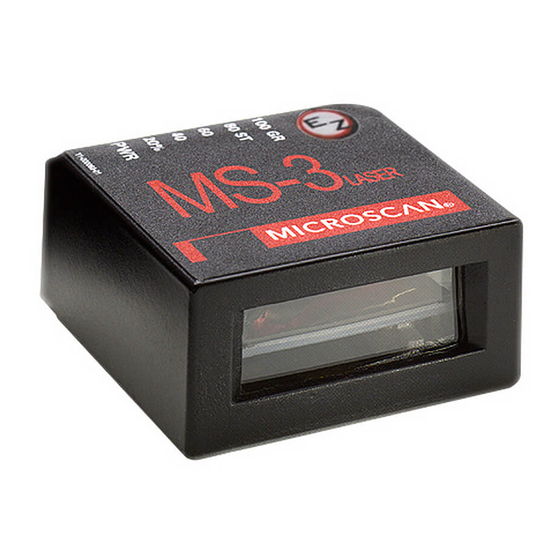
- Page 6 About the MS-3 Laser Scanner About the MS-3 Laser Scanner The MS-3 is an ultra-compact scanner that can decode high density symbols from 2 to 10 inches at a 70 degree scan angle, at speeds of 300 to 1,000 decodes per second, with a power draw of only 300mA at 5V.
- Page 7 European models must use a similarly rated Class I or Class II power supply that is certified to comply with standard for safety EN 60950. Based on the assessment of IEC 60825-1 3rd Edition (2014), the MS-3 does not exceed the AEL of a Class 1 laser product.
- Page 8 • Beam Divergence: 0.6˚ (typ.) • Pulse Duration: 38µs • Maximum Power: 1mW • Based on the assessment of IEC 60825-1 3rd Edition (2014), the MS-3 does not exceed the AEL of a Class 1 laser product. Location of the MS-3’s laser aperture:...
- Page 9 Introduction Warning and Caution Summary (cont.) Warning Label Placement These labels are located on the MS-3 Laser Scanner: MS-3 Laser Scanner User Manual...
- Page 10 The MS-3 has been tested by an independent electromagnetic compatibility laboratory in accordance with the applicable specifications and instructions. The MS-3 is compliant with FDA performance standards for laser products except for deviations pursuant to laser notice no. 50, dated June 24, 2007.
- Page 11 The information provided in this certification notice is correct to the best of Omron Microscan’s knowledge at the date of publication. This notice is not to be considered a warranty or quality specification. Users are responsible for determining the applicability of any RoHS legislation or regulations based on their individual use of the product.
- Page 12 MS-3 Laser Scanner User Manual...
- Page 13 This section is designed to get the scanner up and running quickly so the user can get a sense of its capabilities and test sample bar code symbols. Detailed setup information for configuring the scanner for your specific application can be obtained in the subsequent chapters. MS-3 Laser Scanner User Manual...
-
Page 14: Step 1 Hardware Required
MS-3 Hardware Configuration Caution: If using your own power supply, be certain that it is wired correctly and supplied voltage is within the +10-28VDC limits. Incorrect wiring or voltage can cause software or equipment failures. MS-3 Laser Scanner User Manual... -
Page 15: Step 2 Connect The System
47 feet provided it does not include power input. 2. If using your own null modem RS-232 host cable, be certain that the host’s TxD connects to the reader’s RxD and the reader’s TxD connects to the host’s RxD. MS-3 Laser Scanner User Manual... -
Page 16: Step 3 Position Symbol And Scanner
Note: If using an I 2/5 symbol, verify that the number of characters in the symbol being scanned matches the symbol length enabled for the I 2/5 symbol type. (Default is 10 and 6.) “Interleaved 2 of 5” on page 5-13. MS-3 Laser Scanner User Manual... -
Page 17: Step 4 Install Esp
(XP or above), you can use ESP (Easy Setup Program) for configuration and control. To install ESP from the Omron Microscan Tools Drive: • Insert your Omron Microscan Tools Drive into a USB port on your computer. • Click Setup.exe and follow the prompts. -
Page 18: Step 5 Select Scanner Model
When you start the program, the following menu will appear: 1. Select MS-3 Laser from the menu and click OK. If you do not want to make this selection every time you load ESP, uncheck “Show this window at Startup”. -
Page 19: Step 6 Autoconnect
Tip: If you do not see the CONNECTED or DISCONNECTED message at the bottom of your dialog, try expanding the ESP window horizontally. Note: When you connect to the reader, the reader’s settings will be loaded into ESP. MS-3 Laser Scanner User Manual... -
Page 20: Step 7 Test For Read Rate
With this test you can learn the percentage of decodes per images captured by observing the LEDs (20% through 100%) on the top of the MS-3 which are active during a read rate test. If the results are not satisfactory, move on to Step 8 — “Calibrate the Scanner”. -
Page 21: Step 8 Calibrate The Reader
Power and beeps and see two performance LEDs turn amber Read rate to indicate that the calibration is in progress. performance The scanner will beep once at the end of calibration. LEDs EZ Button MS-3 Laser Scanner User Manual... -
Page 22: Step 9 Save Calibration Settings
Save Calibration Settings Step 9 — Save Calibration Settings After calibrating the MS-3, you can save your new settings to be available at power-on. By ESP Caution: If you have settings in the scanner that you have not yet loaded into ESP, the ESP settings will overwrite the scanner’s settings when you save. -
Page 23: Step 10 Configure The Reader
A-13 and "Summary of Utilities Commands" on page 11-3. Note: You can learn the current setting of any parameter by inserting a question mark after the number, as in <K100?>. To see all K commands, send <K?>. 1-11 MS-3 Laser Scanner User Manual... - Page 24 Configure the Reader 1-12 MS-3 Laser Scanner User Manual...
- Page 25 When you start up ESP, unless otherwise specified, you will enter the EZ Mode for initial setup. From there, you move easily into the App Mode (application mode) where you can access several configuration and utilities menus. MS-3 Laser Scanner User Manual...
-
Page 26: Ez Mode
Click Stop to end the test. Calibrate Some models include a calibration routine that will optimize reads by comparing read rates at various settings in focal lengths, scan speeds, and gain settings. MS-3 Laser Scanner User Manual... -
Page 27: Chapter 2 Using Esp
Note: The App Mode and EZ Mode buttons appear in the same position to allow easy switching between these primary modes. Note: For specific information on any of the icons shown above in the operations bar or configuration bar, see the corresponding sections of this manual. MS-3 Laser Scanner User Manual... - Page 28 ESP and the reader, and ESP and the host hard drive. (Save to Scanner) (Receive Scanner Settings) Import/Export Import converts the ASCII settings from a text file to ESP configuration settings. Export converts the active ESP configuration settings to an ASCII text file. MS-3 Laser Scanner User Manual...
- Page 29 Model menu and that the same menu is repeated when clicking the Switch Model icon. When you save your ESP file, you will be saving the settings of all the models defined in a single ESP file. MS-3 Laser Scanner User Manual...
-
Page 30: Application Mode
Toolbar Style By user selection, displays toolbar buttons as icons, text only, or both (default). Enable ‘Send and Save as Customer Defaults’ At startup, enables the Send and Save as Factory option in the Send/Recv command. MS-3 Laser Scanner User Manual... - Page 31 Display Incoming Data Even When Not in Focus When Display Incoming Data Even When Not in Focus is enabled, data from the scanner will continue to appear in the Terminal even when ESP is not the top window. MS-3 Laser Scanner User Manual...
- Page 32 Example: A bar width of 13 mils is 0.013 inches. Caption Allows the user to define a caption for the symbol, and to determine the alignment of the caption in relation to the symbol. MS-3 Laser Scanner User Manual...
- Page 33 Sends an XON (Begin Transmission) command to the reader before starting Autoconnect. Ask to Save ESP File when Quitting When enabled, prompts the user to save a .esp file when ending a session. The .esp file will be saved in the location of your choice. MS-3 Laser Scanner User Manual...
- Page 34 Menu Toolbar Connect to Readers via TCP/IP When enabled, shows a TCP/IP option on the Connection Wizard. Use Default Storage Location When enabled, automatically stores data in ESP’s Application Data folder. 2-10 MS-3 Laser Scanner User Manual...
- Page 35 Note: Memos must be saved in a .esp file if you want them to available in your next session. If you do not save your current session, any memos that you have entered during the session will be discarded, and will be unavailable in your next session. 2-11 MS-3 Laser Scanner User Manual...
-
Page 36: Connect Menu
4. Select the concentrator’s host port communications settings. When you click Connect, you will be connecting to your concentrator, which can then relay commands to the scanner whose address was set in the Multidrop Settings dialog. 5. Click Connect. 2-12 MS-3 Laser Scanner User Manual... - Page 37 7. Retrieve Scanner Settings to upload scanner’s configuration. If upload fails, return to the Connection Settings dialog and make the necessary changes. 8. Follow the same procedure for connecting other scanners to your multidrop network. 2-13 MS-3 Laser Scanner User Manual...
-
Page 38: View
Create a caption for the symbol that matches or describes the encoded data. The symbol will be displayed in the field at the bottom of the Bar Code Dialog. 2-14 MS-3 Laser Scanner User Manual... -
Page 39: Navigating In Esp
4. Left-click again on the open screen to complete the selection. 5. Right-click on the open screen and select Save to Reader to implement the command in the scanner. The command can be sent without saving, or sent and saved simultaneously. 2-15 MS-3 Laser Scanner User Manual... -
Page 40: Send/Receive Options
Defaults’ in ESP Preferences in the Options menu.) Use this to save your own set of default settings that you can quickly retrieve with a <Zrc> command. For more on defaulting and saving settings, see "Defaulting/Saving/Resetting" on page A-16. 2-16 MS-3 Laser Scanner User Manual... - Page 41 Also, if there is a corresponding ESP menu item, the ESP Value column for that item will be blank following a Receive Reader Settings command. 1. From the Send/Recv button or by right-clicking in any blank section of a tree control view. 2-17 MS-3 Laser Scanner User Manual...
- Page 42 Send/Receive Options 2-18 MS-3 Laser Scanner User Manual...
-
Page 43: Communications
Data Bits = Seven Flow Control = None Note: You can learn the current setting of any parameter by inserting a question mark after the number, as in <K100?> To see all “K” commands, send <K?>. MS-3 Laser Scanner User Manual... -
Page 44: Communications By Esp
<K100,baud,parity,stop bits,data bits> Host Protocol <K140,protocol> Host RS422 Status <K102,status> <K101,aux port mode,baud rate,parity,stop bits,data bits,daisy chain Aux Port Parameters status,daisy chain ID> Preamble <K141,preambole status,preamble> Postamble <K142,postamble status,postamble> LRC Status <K145,status> Intercharacter Delay <K144,intercharacter delay> MS-3 Laser Scanner User Manual... -
Page 45: Password Protection
Serial Cmd: <K733password,new password> Note: Follow this with a <Z> <Zc> to save for power-on. Default: MICRO Options: Any ASCII string up to 8 characters. MS-3 Laser Scanner User Manual... -
Page 46: Rs-232/422 Host Port
Only changed if necessary to match host setting. Definition: One or two bits added to the end of each character to indicate the end of the character. Serial Cmd: <K100,baud rate,parity,stop bits,data bits> Default: Options: 0 = One 1 = Two MS-3 Laser Scanner User Manual... - Page 47 Point-to-Point (standard) Usage: Used only with RS232 or RS422. Definition: Standard Point-to-Point requires no address and sends data to the host whenever it is available, without any request or handshake from the host. Serial Cmd: <K140,0> MS-3 Laser Scanner User Manual...
- Page 48 Definition: Like Point-to-Point, Polling Mode D requires a dedicated connection to the host; but unlike Point-to-Point, it requires an address and must wait for a poll from the host before sending data. Serial Cmd: <K140,4> MS-3 Laser Scanner User Manual...
- Page 49 User Defined Address Definition: User Defined is considered to be in a polled mode only if an address has been assigned. Serial Cmd: <K140,6,RES,address,REQ,EOT,STX,ETX,ACK,NAK,from host> Default: No address Options: Any ASCII character except a null. MS-3 Laser Scanner User Manual...
- Page 50 If From Host is disabled, the defined protocol is not included. If From Host is enabled, the defined protocol must be included. Serial Cmd: <K140,6,RES,address,REQ,EOT,STX,ETX,ACK,NAK,from host> Default: Disabled Options: 0 = Disabled 1 = Enabled MS-3 Laser Scanner User Manual...
- Page 51 Note: Typically, parameters in User Defined Multidrop are defined by first enabling Mul- tidrop, then enabling User Defined Multidrop. This pre-loads multidrop characters into the parameters. Then changes are made to individual characters to match the host or other requirements. MS-3 Laser Scanner User Manual...
- Page 52 Whenever RS422 is disabled, RS232 is enabled in the background. However, when Multi- drop is enabled, the functioning protocol is RS485 regardless of the displayed status of RS422. Before enabling RS422, first double-check that Multidrop is not enabled. 3-10 MS-3 Laser Scanner User Manual...
-
Page 53: Rs-232 Auxiliary Port
ID status,daisy chain ID> Default: 9600 Options: 0 = 600 3 = 4800 6 = 38.4K 1 = 1200 4 = 9600 7 = 57.6K 2 = 2400 5 = 19.2K 8 = 115.2K 3-11 MS-3 Laser Scanner User Manual... - Page 54 Only changed if necessary to match host setting. Definition: Number of bits in each character. Serial Cmd: <K101,aux port mode,baud rate,parity,stop bits,data bits,daisy chain ID status,daisy chain ID> Default: Seven Options: 0 = Seven 1 = Eight 3-12 MS-3 Laser Scanner User Manual...
- Page 55 ID status,daisy chain ID> Default: Disabled Options: 0 = Disabled 1 = Transparent 2 = Half duplex 3 = Full duplex 4 = Daisy chain 5 = Command Processing 3-13 MS-3 Laser Scanner User Manual...
- Page 56 Host • All host data is echoed to the auxiliary port in Port unpolled and polled mode. Scanner Serial Cmd: <K101,aux port mode,baud rate,parity,stop bits,data bits,daisy chain ID status,daisy chain ID> 1 = Transparent 3-14 MS-3 Laser Scanner User Manual...
- Page 57 Data is initiated from the Host • All host data is echoed to the auxiliary port in unpolled mode. Host Port Scanner Serial Cmd: <K101,aux port mode,baud rate,parity,stop bits,data bits,daisy chain ID status,daisy chain ID> 2 = Half Duplex 3-15 MS-3 Laser Scanner User Manual...
- Page 58 Data initiated from the Host Host • All host data is echoed to the auxiliary port in Port unpolled mode. Scanner Serial Cmd: <K101,aux port mode,baud rate,parity,stop bits,data bits,daisy chain ID status,daisy chain ID> 3 = Full duplex 3-16 MS-3 Laser Scanner User Manual...
- Page 59 The above example is based on the best case. Other factors such as baud rate, dynamic focus timing, number of characters in a given symbol, and the number of secondary scanners in the daisy chain can affect timing and may need to be included in your calculations for complete accuracy. 3-17 MS-3 Laser Scanner User Manual...
- Page 60 2. If a reset occurs, all data will be transmitted to the host port. Serial Cmd: <K101,aux port mode,baud rate,parity,stop bits,data bits,daisy chain ID status,daisy chain ID> Options: 5 = Command Processing 3-18 MS-3 Laser Scanner User Manual...
- Page 61 A one or two character prefix which identifies the particular daisy chain scanner from which the data is being sent. Serial Cmd: <K101,aux port mode,baud rate,parity,stop bits,data bits,daisy chain ID sta- tus,daisy chain ID> Default: Options: Any one or two ASCII characters. 3-19 MS-3 Laser Scanner User Manual...
-
Page 62: Preamble
This has the effect of allowing the control key to be recognized as a part of the control character. Next hold down the control key while typing the desired character. Example: Space CNTL-m to enter ^M. 3-20 MS-3 Laser Scanner User Manual... -
Page 63: Postamble
This has the effect of allowing the control key to be recognized as a part of the control character. Next hold down the control key while typing the desired character. Example: Space CNTL-m Space CNTL-j to enter ^M^J. 3-21 MS-3 Laser Scanner User Manual... -
Page 64: Lrc Status
Definition: The time interval in milliseconds between individual characters transmitted from the scanner to the host. Serial Cmd: <K144,intercharacter delay> Default: Options: 0 to 255 (in milliseconds). Zero (0) causes no delay between characters. 3-22 MS-3 Laser Scanner User Manual... - Page 65 ESP or serial commands. Note: You can learn the current setting of any parameter by inserting a question mark after the number, as in <K100?>. To see all “K” commands, send <K?>. MS-3 Laser Scanner User Manual...
-
Page 66: Read Cycle By Esp
Scan Speed <K500,scan speed> Symbol Detect/Transition <K505,symbol detect status,transition counter> Maximum Element <K502,maximum element> Scan Width Enhance <K511,scan width enhance> <K700, laser on/off status,laser framing status,laser on position, Laser Controls laser off position,laser power> MS-3 Laser Scanner User Manual... -
Page 67: Multisymbol
4. The maximum number of characters in any one bar code (other than PDF417) is 64. 5. The maximum number of characters in a single scan line is (Code 39). 6. The maximum number of characters for all symbols is 392, including preamble, separators, and LRC. MS-3 Laser Scanner User Manual... -
Page 68: Number Of Symbols
Number of Symbols Definition: Number of Symbols allows the user to define up to 6 symbols that can be read in a single read cycle. Serial Cmd: <K222,number of symbols,multisymbol separator> Default: Options 1 to 6 MS-3 Laser Scanner User Manual... - Page 69 Note: If Multisymbol Separator has been changed to any character other than the default comma and you wish to re-define the separator as a comma, use ESP or the embedded menu. Default: (comma) Options: Any available ASCII character, except < > NUL. MS-3 Laser Scanner User Manual...
-
Page 70: Trigger
In Continuous Read, trigger input options are disabled, the scanner is always in the read cycle, and it will attempt to decode and output every scan crossing a symbol.When To Output and Noread options have no affect on Continuous Read. Serial Cmd: <K200,0> MS-3 Laser Scanner User Manual... - Page 71 Note: If Trigger is set to Continuous Read 1 Output, Number of Symbols will default back to 1 (if set to any number greater than 1). MS-3 Laser Scanner User Manual...
- Page 72 Rising edge is the trigger signal associated with the appearance of an object. Falling edge is the trigger signal associated with the subsequent disappearance of the object. MS-3 Laser Scanner User Manual...
- Page 73 Rising edge is the trigger signal associated with the appearance of an object. Falling edge is the trigger signal associated with the subsequent disappearance of the object. MS-3 Laser Scanner User Manual...
- Page 74 Definition: In this mode the scanner accepts either a serial ASCII character or an external trigger pulse to start the read cycle. Serial Cmd: <K200,5> 4-10 MS-3 Laser Scanner User Manual...
- Page 75 Users can select the trigger polarity that will operate with their systems. Definition: Determines whether a positive or negative transition will initiate the read cycle. Serial Cmd: <K202,external trigger state> Default: Positive Options: 0 = Negative 1 = Positive 4-11 MS-3 Laser Scanner User Manual...
-
Page 76: Serial Trigger
Note: The following characters cannot be used as serial trigger characters: NUL (0x00), an existing host command character, or an online protocol character. Note: Serial Data or Serial Data & Edge triggering mode must be enabled for Serial Trigger Character to take effect. 4-12 MS-3 Laser Scanner User Manual... - Page 77 < and >. Serial Cmd: <K230,stop trigger character> Default: Null (disabled) Options: Two hex digits representing an ASCII character except <, >, XON and XOFF. See Appendix E, "ASCII Table", for ASCII character information. 4-13 MS-3 Laser Scanner User Manual...
-
Page 78: End Of Read Cycle
With External Level enabled, the read cycle does not end until the falling edge trigger or a timeout occurs. The next read cycle does not begin until the next rising edge trigger. 4-14 MS-3 Laser Scanner User Manual... - Page 79 Note: A minimum setting of 2 is recommended. Note: Timeout or Timeout or New Trigger under End of Read Cycle must be enabled for Read Cycle Timeout to take effect. 4-15 MS-3 Laser Scanner User Manual...
-
Page 80: Decodes Before Output
If it doesn’t achieve the number of good reads during the read cycle, then a noread will be sent. Note: Higher settings will decrease throughput speed. Serial Cmd: <K221,number before output,decodes before output mode> Default: Options: 1 to 255 4-16 MS-3 Laser Scanner User Manual... -
Page 81: Scanner Setup
Allows the user to set the number of scans per second by controlling the spinning mirror motor speed. Serial Cmd: <K500,scan speed> Default: (x 10) Low density scanner (x 10) High density scanner Options: 300 to 1000 4-17 MS-3 Laser Scanner User Manual... - Page 82 Finds the leading edge of a symbol by looking for a 40µS quiet zone fol- lowed by the number of transitions set in "Transition Counter" (page 4- 20), stores the highest value of the samples, and adjusts the AGC accord- ingly at the end of the scan. 4-18 MS-3 Laser Scanner User Manual...
- Page 83 AGC routines. When enabled, a bad symbol or no symbol message can be output rather than a noread message. Serial Cmd: <K505,symbol detect status,transition counter> Default: Disabled Options: 0 = Disabled 1 = Enabled 4-19 MS-3 Laser Scanner User Manual...
- Page 84 70-80% of total scan width. Definition: Scan width Enhance tends to trade depth for width. Disable if outside edge/long range performance is needed. Serial Cmd: <K511,scan width enhance> Default: Enabled Options: 0 = Disabled 1 = Enabled 4-20 MS-3 Laser Scanner User Manual...
-
Page 85: Laser Setup
Note: Because scan widths are not always perfectly symmetrical, the most effective way to setup laser framing is to experiment with the Laser On Position and Laser Off Position commands until you get the best results. 4-21 MS-3 Laser Scanner User Manual... - Page 86 Laser On Position for an actual scan to take place. Laser Off Position Serial Cmd: <K700,laser on/off status,laser framing status,laser on position,laser off position,laser power> Default: Options: 20 to 95 4-22 MS-3 Laser Scanner User Manual...
- Page 87 This parameter allows the user to select a laser power setting as follows: Serial Cmd: <K700,laser on/off status,laser framing status,laser on position,laser off position,laser power> Default: High Options: 0 = Low (~0.6mW) 1 = Medium (~1.0mW) 2 = High (~1.5mW) 4-23 MS-3 Laser Scanner User Manual...
- Page 88 Laser Setup 4-24 MS-3 Laser Scanner User Manual...
-
Page 89: Symbologies
ESP or serial commands. 1. If using an I 2/5 symbol, verify that the number of characters in the symbol being scanned matches the code length enabled for the I 2/5 symbol type (default is 10 and 6). MS-3 Laser Scanner User Manual... -
Page 90: Symbologies By Esp
UPC-A> Code 93 <K475,status,fixed symbol length status,symbol length> <K477,status,fixed bar length status,fixed bar length,min. no. of Pharmacode bars,bar widths,direction,fixed threshold value> Narrow Margins/ <K450,narrow margins status,symbology ID status> Symbology ID Background Color <K451,background color> MS-3 Laser Scanner User Manual... -
Page 91: Code 39
Serial Cmd: <K470,status,check digit status,check digit output,large intercharacter gap,fixed symbol length status,symbol length,full ASCII set> Default: Disabled Options: 0 = Disabled 1 = Enabled MS-3 Laser Scanner User Manual... - Page 92 (this does not include start and stop and check digit characters). The scan- ner ignores any symbol not having the specified length. Serial Cmd: <K470,status,check digit status,check digit output,large intercharacter gap,fixed symbol length status,symbol length,full ASCII set> Default: Default: 1 to 64 MS-3 Laser Scanner User Manual...
- Page 93 ASCII character set, from 0 to 255. Serial Cmd: <K470,status,check digit status,check digit output,large intercharacter gap,fixed symbol length status,symbol length,full ASCII set> Default: Disabled Options: 0 = Disabled 1 = Enabled MS-3 Laser Scanner User Manual...
-
Page 94: Code 128
<K474,status,fixed symbol length status,fixed symbol length,EAN-128 status,output format,application record separator status,application record separator character,application record brackets,application record padding> Default: Options: 1 to 64 Note: Fixed Symbol Length Status must be enabled for Symbol Length to take effect. MS-3 Laser Scanner User Manual... - Page 95 (zeros) for variable length fields. Note: If an illegal Application Record format is detected, the scanner will process it as a noread and output a noread message (if enabled). MS-3 Laser Scanner User Manual...
- Page 96 Default: Disabled Options: 0 = Disabled 1 = Enabled Note: Output Format must be set to Application Record before this parameter can take effect. MS-3 Laser Scanner User Manual...
- Page 97 Default: Disabled Options: 0 = Disabled 1 = Enabled Note: Output Format must be set to Application Record before this parameter can take effect. MS-3 Laser Scanner User Manual...
-
Page 98: Interleaved 2 Of 5
When enabled, a check digit character is sent along with the bar symbol data for added data security. Serial Cmd: <K472,status,check digit status,check digit output status,symbol length #1,symbol length #2,unused,range mode> Default: Disabled Options: 0 = Disabled 1 = Enabled 5-10 MS-3 Laser Scanner User Manual... - Page 99 10 characters plus a check digit, then enable Symbol Length for 12. Note: Typically, when printing an I 2/5 symbol with an odd number of digits, a 0 will be added as the first character. 5-11 MS-3 Laser Scanner User Manual...
- Page 100 <K472,status,check digit status,check digit output status,symbol length #1,symbol length #2,unused,range mode> Default: Options: 0 = Disabled 1 = Enabled When set to Enabled, minimum and maximum symbol lengths will be defined by Symbol Length #1 and Symbol Length #2. 5-12 MS-3 Laser Scanner User Manual...
-
Page 101: Codabar
Serial Cmd: <K471,status,start & stop match status,start & stop output status,large intercharacter gap,fixed symbol length status,symbol length,check digit type,check digit output status> Default: Enabled Options: 0 = Disabled 1 = Enabled 5-13 MS-3 Laser Scanner User Manual... - Page 102 The following rules apply: Serial Cmd: <K471,status,start & stop match status,start & stop output status,large intercharacter gap,fixed symbol length status,symbol length,check digit type,check digit output status> Default: Any/Minimum Options: 0 = Disabled 1 = Enabled 5-14 MS-3 Laser Scanner User Manual...
- Page 103 When disabled, symbol data is sent without the check digit. Serial Cmd: <K471,status,start & stop match,start & stop output status,large interchar- acter gap,fixed symbol length status,symbol length,check digit type,check digit output status> Default: Disabled Options: 0 = Disabled 1 = Enabled 5-15 MS-3 Laser Scanner User Manual...
-
Page 104: Upc/Ean
UPC version A symbols is not desired, disable EAN. Note: The extra character identifies the country of origin. Serial Cmd: <K473,UPC status,EAN status,supplementals status,separator status,sep- arator character,unused,UPC-E output as UPC-A> Default: Disabled Options: 0 = Disabled 1 = Enabled 5-16 MS-3 Laser Scanner User Manual... - Page 105 Supplementals is set to Enabled or Required. Serial Cmd: <K473,UPC status,EAN status,supplementals status,separator sta- tus,separator character,unused,UPC-E output as UPC-A> Default: Disabled Options: 0 = Disabled 1 = Enabled 5-17 MS-3 Laser Scanner User Manual...
- Page 106 Useful for applications that require UPC-A output. Definition: Allows the user to change the output from UPC-E to UPC-A. Serial Cmd: <K473,UPC status,EAN status,supplementals status,separator status,sep- arator character,unused,UPC-E output as UPC-A> Default: (comma) Options: Any ASCII character 5-18 MS-3 Laser Scanner User Manual...
-
Page 107: Code 93
(this does not include start and stop and check digit characters). The scan- ner ignores any symbol not having the specified length. Serial Cmd: <K475,status,fixed symbol length status,fixed symbol length> Default: Options: 1 to 64 5-19 MS-3 Laser Scanner User Manual... -
Page 108: Pharmacode
Default: Options: 2 to 16 Minimum Bars (Pharmacode) Serial Cmd: <K477,status,fixed bar count status, fixed bar count, min. no. of bars, bar widths,direction,fixed threshold value> Default: Options: 2 to 16 5-20 MS-3 Laser Scanner User Manual... - Page 109 Fixed Threshold Value (Pharmacode) Definition: Used when Bar Width Status field is set to Fixed Threshold Value. Serial Cmd: <K477,status,fixed bar count status,fixed bar count,min. no. of bars, bar widths,direction,fixed threshold value> Default: Options: 1 to 65535 5-21 MS-3 Laser Scanner User Manual...
-
Page 110: Narrow Margins
Narrow Margins is enabled. Serial Cmd: <K450,narrow margins status,symbology id status> Default: Disabled Options: 0 = Disabled 1 = Enabled Note: Do not use Narrow Margins with Large Intercharacter Gap enabled in Code 39 or Codabar. 5-22 MS-3 Laser Scanner User Manual... -
Page 111: Symbology Id
Code 39 symbol with Check Digit and Check Digit Output Status enabled and Full ASCII conversion performed. For Other Symbologies • For Code 128, a indicates EAN-128; otherwise the modifier is a 0. • For all other codes, the modifier is 0. 5-23 MS-3 Laser Scanner User Manual... -
Page 112: Background Color
Note: If using an I 2/5 symbol, verify that the number of characters in the symbol being scanned matches the symbol length enabled for the I 2/5 symbol type (default is 10 and 6). 5-24 MS-3 Laser Scanner User Manual... -
Page 113: Symbol Ratio Mode
Maximum ratio is set at 5.6:1. A Validate function is not used in this mode. This method may be useful on long symbols where the spot velocity can change throughout the symbol and effect the minimum and maximum bar values. 5-25 MS-3 Laser Scanner User Manual... - Page 114 Maximum ratio is set at 6.2:1. A Validate function is not used in this mode. This method may be useful on long symbols where the spot velocity can change throughout the symbol and effect the minimum and maximum bar values. 5-26 MS-3 Laser Scanner User Manual...
- Page 115 Maximum ratio is set at 2.65:1. A Validate function is not used in this mode. This method may be useful on long symbols where the spot velocity can change throughout the symbol and effect the minimum and maximum bar values. 5-27 MS-3 Laser Scanner User Manual...
- Page 116 Symbol Ratio Mode 5-28 MS-3 Laser Scanner User Manual...
- Page 117 ESP or serial commands. Note: You can learn the current setting of any parameter by inserting a question mark after the number, as in <K100?>. To see all “K” commands, send <K?>. MS-3 Laser Scanner User Manual...
-
Page 118: I/O Parameters By Esp
I/O Parameters by ESP Click this Button to bring up the I/O Parameters menu. To open nested options, single-click the +. To change a setting, double-click the setting and use your cursor to scroll through the options. MS-3 Laser Scanner User Manual... -
Page 119: Chapter 6 I/O Parameters
Output 3 Parameters <K812,output on,polarity,pulse width> <K782,trend analysis mode,number of triggers,number to output Trend Analysis (Output 3) on,decodes/trigger threshold> <K792,usused,service threshold,unused,laser current high,laser Diagnostics (Output 3) current low> Quality Output <K704,quality output separator,reads/trigger status> MS-3 Laser Scanner User Manual... -
Page 120: Symbol Data Output
When set to Match, the scanner transmits symbol data whenever a symbol matches a master symbol. However, if Matchcode Type is Disabled, it transmits on any good read. Note: A noread can still be transmitted if Enabled. MS-3 Laser Scanner User Manual... - Page 121 It’s typically used in tracking applications in which each object is uniquely identified. Definition: With Good Read enabled, the scanner transmits symbol data on any good read regardless of Matchcode Type setting. Note: A noread can still be transmitted if enabled. MS-3 Laser Scanner User Manual...
- Page 122 Start of read cycle End of read cycle Read cycle Timeout Host The point at which the activates trigger host expects output Read Cycle MS-3 Laser Scanner User Manual...
-
Page 123: Message Output
Does the scanner decode the symbol? Noread Is Symbol message sent Detect enabled? (if enabled) Bad Symbol Transition message sent Counter Threshold (if enabled) met? No Symbol message sent (if enabled) End of read cycle MS-3 Laser Scanner User Manual... -
Page 124: Noread Message
Note: Noread Message will only be transmitted if Symbol Output ( "Symbol Data Out- put Status" on page 6-4) is set to Match, Mismatch or Good Read. Noread Message can be set to any ASCII characters except NULL <> (comma). MS-3 Laser Scanner User Manual... -
Page 125: Bad Symbol Message
The Bad Symbol output is tied to the transition counter. If during a read cycle no symbol is decoded and the required setting for the Transition Sample Threshold is met, a user defined message will be sent to the host. MS-3 Laser Scanner User Manual... -
Page 126: No Symbol Message
<K716,no symbol status,no symbol message> Default: Disabled Options: 0 = Disabled 1 = Enabled No Symbol Message Serial Cmd: <K716,no symbol status,no symbol message> Default: NO_SYMBOL Options: Up to 10 ASCII characters (except NUL) 6-10 MS-3 Laser Scanner User Manual... -
Page 127: Beeper
• a <Z>, <Zp>, <Zd>, or <K,1> command is sent. Beeper Output Condition Serial Cmd: <K702,beeper output> Default: On Good Read Options: 0 = Disabled 1 = On Good Read 2 = On Noread 6-11 MS-3 Laser Scanner User Manual... -
Page 128: Partial Output
<K703,partial output status,start position,length> Default: Options: 1 to 64 Length (Partial Output) Definition: Allows you to determine the number of characters to be transmitted. Serial Cmd: <K703,partial output status,start position,length> Default: Options: 1 to 64 6-12 MS-3 Laser Scanner User Manual... -
Page 129: Serial Verification
Only one bad field needs to be found in order to activate the 5 beep response. Serial Cmd: <K701,serial command echo status,serial command beep status,control/ hex output> Default: Disabled Options: 0 = Disabled 1 = Enabled 6-13 MS-3 Laser Scanner User Manual... - Page 130 For example, a carriage return will be shown as the two characters: ^M. When set to Hex, the output is the hex character. Serial Cmd: <K701,serial command echo status,serial command beep status,control/ output> Default: Control Options: 0 = Control 1 = Hex 6-14 MS-3 Laser Scanner User Manual...
-
Page 131: Ez Button
When enabled, if the EZ Button is held down during power-on, the scanner will default to customer defaults and save for power-on. This is the same as sending a <Zrc> command. Serial Cmd: <K770,global status,default on power-on> Default: Enabled Options: 0 = Disabled 1 = Enabled 6-15 MS-3 Laser Scanner User Manual... - Page 132 Save for Power-on: When when this button position is selected, all scanner settings will be saved to non-volatile memory to be recalled when scanner is powered-on the next time. This is the same as sending the <Z> in the terminal. 6-16 MS-3 Laser Scanner User Manual...
- Page 133 Sleep Mode: If sleep mode is enabled, the EZ Button will shut off the mirror motor and laser. To exit sleep mode, press the EZ Button once quickly. 6-17 MS-3 Laser Scanner User Manual...
- Page 134 Activates a discrete output whenever the symbol data does not match that of the master symbol. Noread Activates a discrete output whenever the symbol data is not decoded before the end of the read cycle. 6-18 MS-3 Laser Scanner User Manual...
- Page 135 Sets the time in 1mS increments that the discrete output remains active. Serial Cmd: <K810,output on,polarity,pulse width,output mode> Default: (50mS) Options: 0 to 65535 (0 to 65.535 seconds). Divide the number entered on the com- mand line by 1000 for time in seconds. 6-19 MS-3 Laser Scanner User Manual...
-
Page 136: Output 1
Note: All of the Output On modes are inhibited when any Output on Warning is active for Output 1 (see <K713> command). 6-20 MS-3 Laser Scanner User Manual... - Page 137 Number to Output On within the trigger window selected in Trigger Evaluation Period. Noread Definition: The output will be activated when the number of noreads equals the value entered for Number to Output On within the trigger window selected in Trigger Evaluation Period. 6-21 MS-3 Laser Scanner User Manual...
- Page 138 In this example, the scanner will activate an output whenever the number of decodes falls below the decodes per trigger threshold (10) for 4 trigger (read cycle) events. Serial Cmd: <K780,trend analysis mode,number of triggers,number to output on,decodes/trigger threshold> Default: Options: 0 to 65535 6-22 MS-3 Laser Scanner User Manual...
- Page 139 Laser Current Low Definition: Activates the output whenever the high current threshold has been met. Will output once. Serial Cmd: <K790,usused,service threshold,unused,laser current high,laser current low> Default: Disabled Options: 0 = Disabled 1 = Enabled 6-23 MS-3 Laser Scanner User Manual...
-
Page 140: Output 2
Diagnostic Warnings (output 2) Definition: Applies warning to Output 2. Serial Cmd: <K791,usused,service threshold,unused,laser current high,laser current low> Diagnostic Warnings to Output 2 has the same parameters and default settings as Diagnostic Warnings to Output 1. 6-24 MS-3 Laser Scanner User Manual... -
Page 141: Output 3
Diagnostic Warnings (output 3) Definition: Applies warning to Output 3. Serial Cmd: <K792,usused,service threshold,unused,laser current high,laser current low> Diagnostic Warnings to Output 3 has the same parameters and default settings as Diagnostic Warnings to Output 1. 6-25 MS-3 Laser Scanner User Manual... -
Page 142: Quality Output
If enabled the decode direction is appended to the barcode output with a quality output separator as an “F” (forward) or an “R” (reverse). Serial Cmd: <K704,quality output separator,reads/trigger status,decode direction sta- tus> Default: Disabled Options: 0 = Disabled 1 = Enabled 6-26 MS-3 Laser Scanner User Manual... -
Page 143: Matchcode
ESP or serial commands. Note: You can learn the current setting of any parameter by inserting a question mark after the number, as in <K100?>. To see all “K” commands, send <K?>. MS-3 Laser Scanner User Manual... -
Page 144: Matchcode By Esp
<K231,master symbol number,master symbol data> Request Master Symbol Information <K231?,master symbol number> Request all Master Symbol Information <K231,?> Delete Master Symbol <K231, master symbol number,> Store Next Symbol as Master Symbol <G master symbol number> MS-3 Laser Scanner User Manual... -
Page 145: Overview Of Matchcode
(see "New Master Pin"on page 7-9). Other Master Symbol Serial Commands See also "Master Symbol Database Size" on page 11-8 for more information details on entering, requesting, and deleting master symbols. MS-3 Laser Scanner User Manual... -
Page 146: Matchcode Type
With Sequential enabled, Sequential Matching determines if a count is in ascending (incremental) or descending (decremental) order. Serial Cmd: <K223,matchcode type,sequential matching,match start position, match length,wild card character,sequence on noread,sequence on mis- match> Default: Increment Options: 0 = Increment 1 = Decrement MS-3 Laser Scanner User Manual... - Page 147 Default: Options: 0 to 64 Note: Match Start Position must be set to 1 or greater to enable this feature. A 0 setting will disable this feature. MS-3 Laser Scanner User Manual...
- Page 148 Wild Card Character allows a user to define a wild card character as part of the master symbol. Serial Cmd: <K223,matchcode type,sequential matching,match start position, match length,wild card character,sequence on noread,sequence on mis- match> Default: (asterisk) Options: Any valid ASCII character MS-3 Laser Scanner User Manual...
- Page 149 007 (sequenced on noread) As an example of Sequence on Noread Disabled, consider the following series of decodes: Master symbol Decoded symbol Master symbol after decode noread 003 (not sequenced) noread 004 (not sequenced) noread 004 (not sequenced) MS-3 Laser Scanner User Manual...
- Page 150 As an example of Sequence On Mismatch Disabled, consider the following decodes: Master symbol Decoded symbol Master symbol after decode 004 (sequenced because of previous match) 006 (sequenced because of previous match) 006 (not sequenced because of previous mismatch) MS-3 Laser Scanner User Manual...
-
Page 151: New Master Pin
For example, if Number of Symbols is set to 3 and New Master Pin is then activated, at the end of the next read cycle, the decoded symbols will be saved as master symbols 1, 2, and 3. MS-3 Laser Scanner User Manual... -
Page 152: Master Symbol Database
Delete Master Symbol Data Definition: Delete Master Symbol Data allows you to delete an enabled master sym- bol. Serial Cmd: Send <K231,master symbol number,> to delete the master symbol. Options: 1 to 10 7-10 MS-3 Laser Scanner User Manual... -
Page 153: Diagnostics
ESP or serial commands. Note: You can learn the current setting of any parameter by inserting a question mark after the number, as in <K100?>. To see all “K” commands, send <K?>. MS-3 Laser Scanner User Manual... -
Page 154: Diagnostics By Esp
Command Title Format Counts, Power-on/Resets <K406, power-on,resets,power-on saves,custom default saves> Hours Since Last Reset <K407?> (read only— returns: hours,minutes) <K411,laser high status,laser high message,laser low status, Laser High/Low laser low message> Service Message <K409,status,service message,threshold,resolution> MS-3 Laser Scanner User Manual... -
Page 155: Diagnostic Messages Overview
Note: When enabled, the error condition will override all other operational modes configured for the output. When enabled, laser current and NOVRAM warning messages will be transmitted to the host or any active port whenever the pre-defined condi- tions are met. MS-3 Laser Scanner User Manual... -
Page 156: Counts
ESD transients. Definition Returns Resets for all the “warm” resets, including <A>, <Ard>, <Arp> <Arc>. Serial Cmd: Send <K406?> Returns <K406,power-on,resets,power-on saves,custom default saves> Read Only 0 to 65,535 powerups, 0 to 65,535 resets. Ranges: MS-3 Laser Scanner User Manual... - Page 157 Useful for detecting unwanted resets caused by power supply problems or ESD transients. Definition Returns the number of customer default saves: <Zrd>. Serial Cmd: Send <K406?> Returns <K406,power-on,resets,power-on saves,custom default saves> Read Only 0 to 65,535 powerups, 0 to 65,535 resets. Ranges: MS-3 Laser Scanner User Manual...
-
Page 158: Hours Since Last Reset
Useful as a troubleshooting tool that can help pinpoint the cause of a reset. Definition: Records the number of hours and minutes of operation since the last sys- tem reset. Serial Cmd: Send <K407?> Returns <K407hours,minutes> Read Only 0 to 23 hours, 0 to 59 minutes. Ranges: MS-3 Laser Scanner User Manual... -
Page 159: Laser High
Laser High Message Definition: Defines the Laser High message. Serial Cmd: <K411,laser high status,laser high message,laser low status,laser low message> Default: HIGH-LASER Options: Any 1 to 10 character ASCII string except NUL, <, or >. MS-3 Laser Scanner User Manual... -
Page 160: Laser Low
Laser Low Message Definition: Defines the Laser Low message. Serial Cmd: <K411,laser high status,laser high message,laser low status,laser low message> Default: LOW-LASER Options: Any 1 to 10 character ASCII string except NUL, <, or >. MS-3 Laser Scanner User Manual... -
Page 161: Service Message
Serial Cmd: <K409,status,service message,threshold,resolution> Default: (5 minutes) Options: 1 to 65,535 Resolution Definition: Records time in seconds or minutes. Serial Cmd: <K409,status,service message,threshold,resolution> Default: Seconds Options: 0 = Seconds 1 = Minutes MS-3 Laser Scanner User Manual... - Page 162 Service Message 8-10 MS-3 Laser Scanner User Manual...
- Page 163 ESP, serial command, and embedded menus. For most applications, calibration is the only optical setup required. This section also includes an explanation of Auto Frame commands, the routine for constraining the width of the scan beam. MS-3 Laser Scanner User Manual...
- Page 164 2. Note: If using an I 2 of 5 label, verify that the number of characters in the label being scanned matches the code length enabled for the I 2 of 5 code type (default is 10 and 6). See "Interleaved 2 of 5"on page 5-13. MS-3 Laser Scanner User Manual...
- Page 165 Save to save for power-on (same as a <Z> command). Calibration by Serial Command Send an <@CAL> command to optimize motor speed, laser power and gain level. Send a <Z> <Zd> command to save settings. MS-3 Laser Scanner User Manual...
- Page 166 No other keystroke has any effect while in calibration. 3. Wait for the calibration routine to cycle through its settings. A Calibration in Progress message will be displayed. A new text line will appear below the menu displaying the progress of the calibration. MS-3 Laser Scanner User Manual...
- Page 167 “DO YOU WANT TO SAVE THESE SETTINGS FOR POWER-ON? Y/N” These settings include Motor Speed, Gain, AGC Level, Laser Power and Laser Frame. Typing will cause the scanner to be reset without saving the settings for power-on. MS-3 Laser Scanner User Manual...
-
Page 168: Auto Frame
Constrained Scan Beam Width Framing Defaults You can also adjust the framing manually by moving the selectors while visually observing the size of the scan beam. MS-3 Laser Scanner User Manual... - Page 169 Auto Frame by Embedded Menu From the embedded menus, select Scanner Setup 2. From here you can use the Laser On Position %and Laser Off Position % to constrain the width of the scan beam. MS-3 Laser Scanner User Manual...
- Page 170 Auto Frame MS-3 Laser Scanner User Manual...
- Page 171 ESP or serial commands. Note: You can learn the current setting of any parameter by inserting a question mark after the number, as in <K100?>. To see all “K” commands, send <K?>. 10-1 MS-3 Laser Scanner User Manual...
-
Page 172: Terminal Window
The Terminal screen also displays bar code data or information from the scanner (in blue). You can also right click in the Terminal screen to bring up a handy option box. 10-2 MS-3 Laser Scanner User Manual... -
Page 173: Find Function
3. The first instance of ABC will be high-lighted in the Terminal window. 4. Press the key to search again for the next instance of ABC. 5. Press Shift-F3 to search for the previous instance of ABC. 10-3 MS-3 Laser Scanner User Manual... -
Page 174: Macros
When you click the arrow next to a any macro and select Edit, the following appears: You can edit an existing macro or type in a new macro name and define it in the Macro Value text box. Click OK. 10-4 MS-3 Laser Scanner User Manual... -
Page 175: Terminal Window Menus
• Find Next searches for a user-defined section of text in the Terminal. • Find Previous operates in the same way as Find Next, but searches backward through Terminal text. 10-5 MS-3 Laser Scanner User Manual... - Page 176 Terminal Window Menus 10-6 MS-3 Laser Scanner User Manual...
-
Page 177: 11 Utilities
Note: You can learn the current setting of any parameter by inserting a question mark after the number, as in <K100?>. To see all “K” commands, send <K?>. Note: The characters NULL <> can only be entered through embedded menus, not through ESP or serial commands. 11-1 MS-3 Laser Scanner User Manual... -
Page 178: Utilities By Esp
Utilities by ESP Utilities by ESP Click this button to bring up the Utilities view. Click the tabs to access various ESP utilities. Note: Utility commands are not accessible by embedded menus. 11-2 MS-3 Laser Scanner User Manual... -
Page 179: Summary Of Utilities Commands
Display Application Code Part Number <H> Enable Laser Scanning <I> Disable Laser Scanning <K500,> <KE> Motor On Device Control <K501,> <KF> Motor Off <L1> Programmable Output 1 <L2> Programmable Output 2 <L3> Programmable Output 3 11-3 MS-3 Laser Scanner User Manual... - Page 180 Save current settings for power-on <Zc> Save current settings as customer default parameters <?> Scanner Status Status Requests <?1> Extended scanner status <K?> Configuration status Note: Utility commands are not accessible by embedded menus. 11-4 MS-3 Laser Scanner User Manual...
-
Page 181: Read Rate
End Read Rate Test Sending <J> ends both the Percent test and the Decodes/Second test for both single and multi-symbol. 11-5 MS-3 Laser Scanner User Manual... -
Page 182: Counters
You can access Counters from the Utilities menu. Right-click the appropriate counter option and select Request to display count or Clear to set counter to zero. Or, right-click on Counters and select Request All. 11-6 MS-3 Laser Scanner User Manual... - Page 183 Mismatch Counter With Matchcode enabled, sending <X> displays the number of decoded symbols since the last reset that do not match the master symbol. Mismatch Counter Reset Sending <Y> sets the mismatch counter to zero. 11-7 MS-3 Laser Scanner User Manual...
-
Page 184: Master Database
Master Database tab. 2. Click the Matchcode Type checkbox to enable Matchcode. 3. Set the number of master symbols you want to include. Scroll up or down to set the master symbol database size. 11-8 MS-3 Laser Scanner User Manual... - Page 185 "Maximum Characters for Master Symbol Database", on page 11-10, specifies the maximum number of characters available to each symbol according to the number of master symbols defined, from 1 through 10. See "Master Symbol Database Size" on page 11-8. 11-9 MS-3 Laser Scanner User Manual...
- Page 186 1. Serial Cmd: <Gmaster symbol number> To store the next symbol scanned as master symbol #1 send: <G> <G1>. For all symbols numbers except 1, the number must be included. Options: 1 to 10 11-10 MS-3 Laser Scanner User Manual...
-
Page 187: Digital Bar Code
Zoom In, Zoom Out You can zoom in by sliding the Zoom lever to the right. You may have to scroll right or left to locate your symbol, but the results will be striking. 11-11 MS-3 Laser Scanner User Manual... -
Page 188: Firmware
Caution: Do not interrupt power or disconnect the host cable while download is in progress. Firmware/Checksum Verification From Firmware Verification you can request the part number and checksum from by selecting App Code Boot Code and clicking the accompanying Request... button. 11-12 MS-3 Laser Scanner User Manual... -
Page 189: Device Control
Activates the link between Output 3(+) and Output 3(–) of the host connec- Definition: tor for the duration set by "Pulse Width" on page 6-19. (regardless of Master Symbol or Output 3 status). ESP: Click Output # 3 Pulse to activate. Serial Cmd: <L3> 11-13 MS-3 Laser Scanner User Manual... - Page 190 This feature is useful during extended periods of time when no symbols are being scanned or the scanner is being configured. Definition: Turns the spinning mirror on (if not already running). ESP: Click Send Motor On button. Serial Cmd: <KE> 11-14 MS-3 Laser Scanner User Manual...
-
Page 191: Symbol Type
Code 39 symbols without changing scanner configuration. Sending <R> enables the scanner to decode Codabar symbols without changing scanner configuration. Sending <S> enables the scanner to decode I 2 of 5 symbols without changing scanner configuration. 11-15 MS-3 Laser Scanner User Manual... -
Page 192: Defaulting/Saving/Resetting
Save current settings for power-on <Zc> Save current settings as customer default parameters <Zrd> Recall Omron Microscan default parameters and save for power-on <Zrc> Recall customer parameters and save for power-on See Appendix G, "Defaulting/Saving/Resetting", on page A-20 for complete explanation on resets, saves and defaulting. -
Page 193: Omron Microscan Grading
Utilities Omron Microscan Grading Omron Microscan grading informs the user how the scanner perceives a symbol it is scanning. Except for special circumstances, the slower the scan speed and the closer the symbol is to the focal point, the more accurate the results. - Page 194 • Intercharacter Gap - Measures the largest intercharacter gap within the symbol. If the symbol does not have intercharacter gaps then N/A is output. • Margin - Measures the size of the smallest margin around the symbol. 11-18 MS-3 Laser Scanner User Manual...
-
Page 195: Scanner Status Requests
(35-338201-xx), the fpga part number (5-559001-xx), flash checksum (476C), current RAM parameter checksum (33), and flash parameter checksum (33). <K?> Configuration Command Status Returns the current status of all configuration commands. 11-19 MS-3 Laser Scanner User Manual... - Page 196 Scanner Status Requests 11-20 MS-3 Laser Scanner User Manual...
-
Page 197: Appendices
Appendix I Formulas for Number of Decodes ................A-18 Appendix J Operational Tips ...................... A-21 Appendix K Interface Standards ....................A-22 Appendix L Multidrop Communications..................A-23 Appendix M Troubleshooting ..................... A-28 Appendix N Glossary of Terms ....................A-30 MS-3 Laser Scanner User Manual... -
Page 198: Appendix A General Specifications
Outputs (1, 2, 3): 5V TTL compatible, can sink 10 mA and source 2 mA MS-3 Integral Right Angle Laser Scanner Symbologies Standard: Code 39, Code 128, Interleaved 2 of 5, Codabar, Code 93, UPC/EAN, Pharmacode; Special Option: PDF417 MS-3 Laser Scanner User Manual... - Page 199 Scanner is in read cycle GD/RD/100% Amber On Good Read The MS-3 conforms to the following requirements: • FCC 15.107:2015 Class B Conducted Emissions • FCC 15.109(g):2015 Class B Radiated Emissions CE Mark The MS-3 conforms to the following requirements: •...
- Page 200 Note: For Right Angle option, subtract 0.6” (15 mm) from read range. For Right Angle Fixed Raster option ONLY, subtract 1.1” (28 mm) from 20 mil barcode read range. Read ranges are based upon optimal scan speed for specific symbol density. MS-3 Laser Scanner User Manual...
-
Page 201: Appendix B Electrical Specifications
Output 3 TTL (can sink 10mA and source 2mA) New Master Pin (NPN) Chassis Ground Output 2 TTL (can sink 10mA and source 2mA) Caution: 1. Be sure all cables are connected BEFORE applying power. 2. Always power down BEFORE disconnecting any cables. MS-3 Laser Scanner User Manual... -
Page 202: Appendix C Serial Configuration Commands
Scan Width Enhance <K511,scan width enhance> <K700,laser on/off status,laser framing status,laser on position,laser Laser Setup off position,laser power> Symbologies <K470,status,check digit status,check digit output status,large inter- Code 39 character gap,fixed symbol length status,default symbol length,full ASCII set> MS-3 Laser Scanner User Manual... - Page 203 Output 3 Parameters <K812,output on,output state,pulse width,output mode> <K782,trend analysis mode,number of triggers,number to output Trend Analysis (Output 3) on,decodes/trigger threshold> <K792,over temperature,service threshold,unused,laser current Diagnostics (Output 3) high,laser current low,low temp> MS-3 Laser Scanner User Manual...
- Page 204 In order to communicate with the scanner, you will need to use the following commu-nica- tions settings: Baud = 9600 Parity = Even Stop Bits = Data Bits = Seven Flow Control = None MS-3 Laser Scanner User Manual...
-
Page 205: Appendix D Serial Command Format
For example, if only the last field in the following command is changing, <K100,4,1,0,0> can be entered as <K100,,,0>. • All fields following a modified field can be omitted. For example, to change Baud Rate, send <K100,3>. 1. Many K command will automatically be saved for power-on. MS-3 Laser Scanner User Manual... - Page 206 While it appears that nothing has been assigned, the hex value 20 will be sent during data transmission. To Select NUL as the Character Press SP, then a (zero). It is displayed as <NUL> in the menu when the screen is refreshed. A-10 MS-3 Laser Scanner User Manual...
-
Page 207: Appendix E Ascii Table
Appendices Appendix E — ASCII Table Ctrl “ & < > A-11 MS-3 Laser Scanner User Manual... - Page 208 Protocol Command Control Characters (Mnemonic displayed on (Entered in menu or Effect of Command Code menu) serial command) Reset Request Reset Start of Text End of Text Acknowledge Negative Acknowledge Begin Transmission XOFF Stop Transmission A-12 MS-3 Laser Scanner User Manual...
-
Page 209: Appendix F Defaulting/Saving/Resetting
By using the hardware default to default the power-on settings to the known Omron Microscan default, the user can then recall their previously customer saved settings with the <Arc>... - Page 210 Defaulting/Saving/Resetting Omron Microscan Default Parameters Omron Microscan default parameters are contained in the firmware that cannot be changed. Software Default Omron Microscan default parameters can be recalled (loaded into current settings) with <Ard> command or recalled and saved for power-on with the <Zrd>...
-
Page 211: Appendix G Symbol Configuration
During the configuration mode the LEDs will emit a side-to-side pattern to let you know you are currently ready to configure. You can create your own start symbol by encoding the following in Code 128: FNC4 <_CFG>. A-15 MS-3 Laser Scanner User Manual... - Page 212 To end the read rate test and the symbol configuration program, scan this symbol: This will terminate symbol configuration mode. Changes made in configuration will remain in effect just as would changes made in the menus or by serial commands. A-16 MS-3 Laser Scanner User Manual...
-
Page 213: Appendix H Object Detector
As the item continues to move down the line, its symbol moves into the scanner beam and is read by the scanner. Barcoded Object Barcoded Object Object Detector Scanner Object Detector A-17 MS-3 Laser Scanner User Manual... -
Page 214: Appendix I Formulas For Number Of Decodes
1. The -3 component in the formula is included to allow for AGC acquisition, an incomplete first scan, and an incomplete last scan. This applies only if the number inside the parentheses equals 4 or more. If the number equals 3, then only subtract 2 to derive 1 good scan. A-18 MS-3 Laser Scanner User Manual... - Page 215 (range) from the scanner. Both the top offset and bottom offsets can be adjusted inde- pendently in 255 increments and the resulting arc can vary from 0° to 30°. 1. The number 2 in the SR formula ensures that each symbol receives two full raster sweeps. A-19 MS-3 Laser Scanner User Manual...
- Page 216 Increas- ing the height of a ladder symbol means it will receive more scans. Changing symbol density and/or symbol ratio is another way ranges, decode rates, etc. can be altered. A-20 MS-3 Laser Scanner User Manual...
-
Page 217: Appendix J Operational Tips
• Check the symbol for readability by doing a decode rate test. If there is any question about the symbol's readability, contact your Omron Microscan representative. • After changing any parameter that might affect decode rate, repeat decode rate test. -
Page 218: Appendix K Interface Standards
With Omron Microscan devices, selection of interface is made by pin assignment and, in the case of the host communications, by software switching between RS-232 and RS-422. -
Page 219: Appendix L Multidrop Communications
9. Your scanner is now in multidrop. From here on, you will need to use the concentra- tor to relay commands and data between the scanner or scanners and the host. 10. Next, go to “Connect to Reader via the Concentrator” on the next page. A-23 MS-3 Laser Scanner User Manual... - Page 220 Retrieve Reader Settings to upload scanner’s configuration. If upload fails, return to the Serial Communication Parameters dialog and make the necessary cor- rections. 8. Follow the same procedure for connecting other scanners to your multidrop network. A-24 MS-3 Laser Scanner User Manual...
- Page 221 REQ to the concentrator and request another response. If after three retries (the number of times it transmits a REQ to the concentrator) the scanner receives no response, it ends the transmission with a RES (reset). A-25 MS-3 Laser Scanner User Manual...
- Page 222 If the scanner receives bad data from the concentrator, it transmits a SEL (its select address) and a NAK to the concentrator. The concentrator re-transmits the data up to three times. The concentrator will end the sequence with a RES (reset) if no ACK is received. A-26 MS-3 Laser Scanner User Manual...
- Page 223 Appendices Multidrop Addresses Poll Select Poll Select Multidrop Multidrop Character Character Character Character Address Address ASCII ASCII ASCII ASCII " & < > A-27 MS-3 Laser Scanner User Manual...
-
Page 224: Appendix M Troubleshooting
Other objects in field of view are misleading Try to eliminate shiny objects from the field of the gain control system. view. Scan rate is too fast, exceeding MS-3’s video Slow down the scan rate. bandwidth. Do not violate the 10x rule for quiet zone;... - Page 225 Read Read Control Control Control Boot LEDs Read Read Read Test Test Test Test Test Test Mode Mode Mode Mode Modes Modes Modes Mode Mode Mode Mode Mode Mode 100% BLINK BLINK BLINK BLINK A-29 MS-3 Laser Scanner User Manual...
-
Page 226: Appendix N Glossary Of Terms
Full Duplex — A communication system in which signals can travel simultaneously between devices. Gain — Optimal signal strength. Good Read — A decode. The successful scanning and decoding of the information encoded in a symbol. A-30 MS-3 Laser Scanner User Manual... - Page 227 Picket Fence Orientation — A linear symbol orientation in which the bars are perpendicular to the symbol’s direction of travel. Pitch — Rotation of a symbol around an axis parallel to the symbol length on the substrate. See the illustration below. A-31 MS-3 Laser Scanner User Manual...
- Page 228 Trigger — A signal, transition, or character string that initiates a read cycle. Very Large-Scale Integration (VLSI) — The creation of integrated circuits by combining thousands of transistor-based circuits on a single chip. VLSI — See Very Large-Scale Integration. A-32 MS-3 Laser Scanner User Manual...
Need help?
Do you have a question about the MS-3 and is the answer not in the manual?
Questions and answers