Table of Contents
Advertisement
Quick Links
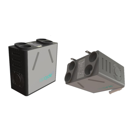
QUIET, EFFICIENT
AND HIGHLY
VERSATILE
Heat Recovery Ventilation
Installation, maintenance & user manual
Applicable to the following aircycle 1.3 & 1.3+ models:
aircycle MVHR
Product Type
c/w Humidistat, Bypass - Wall Mount
c/w Humidistat, Bypass - Floor Mount
c/w Humidistat, Bypass - Ceiling Mount
Product codes shown refer to "Standard" duct configuration.
Add "V" to the end of each product code for an "inverted duct configuration.
aircycle 1.3
Potentiometer Control
AS 90-0103-WINS-01
AS 90-0103-FINS-01
AS 90-0103-CINS-01
aircycle 1.3+
Potentiometer Control
AS 90-0103P-WINS-01
AS 90-0103P-FINS-01
AS 90-0103P-CINS-01
V. 1.3-24-04-19
brookvent.co.uk
Advertisement
Table of Contents

Subscribe to Our Youtube Channel
Related Manuals for BrookVent aircycle 1.3


Summary of Contents for BrookVent aircycle 1.3
- Page 1 QUIET, EFFICIENT AND HIGHLY VERSATILE Heat Recovery Ventilation Installation, maintenance & user manual Applicable to the following aircycle 1.3 & 1.3+ models: aircycle MVHR aircycle 1.3 aircycle 1.3+ Product Type Potentiometer Control Potentiometer Control c/w Humidistat, Bypass - Wall Mount...
-
Page 2: Table Of Contents
Safety ..........................4 Specifications/ Dimensions (mm) ..................6 Installation ........................11 Electrical Connections/ Wiring ..................20 Controls and Settings ......................21 Maintenance ........................27 User Operation ........................35 Trouble Shooting ....................... 40 V. 1.3-24-04-19 brookvent.co.uk www.brookvent.co.uk T: +44 (0) 28 9061 6505... -
Page 3: Introduction
Introduction The Brookvent aircycle 1.3 is a compact and highly efficient Mechanical Heat Recovery Ventilation (HRV/MHRV) system, specifically designed for smaller dwellings and apartments with restricted space. - Page 4 4 years covering parts only. In the instance of a defect, Brookvent may repair the product, replace the product free of charge or refund the cost of the product at Brookvent’s own discretion. In terms of installation, operation and maintenance please follow all instructions provided.
-
Page 5: Safety
Never touch the appliance with wet hands. ▪ The unit is only suitable for 230 VAC/50Hz electric mains. ▪ Never modify the fan or electronics, all repairs must be conducted by Brookvent. ▪ Never connect the power if electronics cover is not fitted. ▪... - Page 6 In new build properties it may be prudent to check/ change your filters after the first 3 months of occupancy depending on the amount of residual ‘building dust’ present within the property. Failure to do so will affect your warranty. Filters can be purchased directly online from brookvent.co.uk V. 1.3-24-04-19 brookvent.co.uk www.brookvent.co.uk...
-
Page 7: Specifications/ Dimensions (Mm)
Specifications/ Dimensions 3.01 WALL MOUNT 3.02 CEILING MOUNT V. 1.3-24-04-19 brookvent.co.uk www.brookvent.co.uk T: +44 (0) 28 9061 6505... - Page 8 3.03 FLOOR MOUNT Duct Connections V. 1.3-24-04-19 brookvent.co.uk www.brookvent.co.uk T: +44 (0) 28 9061 6505...
- Page 9 • Plug and play fan components for easy maintenance Standards: Fully complies with Building Regulations for UK & Ireland SAP Appendix Q Listed | Energy Savings Trust Best Practice | CE V. 1.3-24-04-19 brookvent.co.uk www.brookvent.co.uk T: +44 (0) 28 9061 6505...
- Page 10 SAP Appendix Q Results Airflow: Pressure/ Performance Curve – aircycle 1.3 Aircycle 1.3 600.0 550.0 100% 500.0 450.0 400.0 350.0 300.0 250.0 200.0 150.0 100.0 50.0 10.0 20.0 30.0 40.0 50.0 60.0 70.0 80.0 Airflow (l/s) 100% V. 1.3-24-04-19 brookvent.co.uk www.brookvent.co.uk...
- Page 11 Airflow: Pressure/ Performance Curve – aircycle 1.3+ Aircycle 1.3+ 500.0 100% 450.0 400.0 350.0 300.0 250.0 200.0 150.0 100.0 50.0 Airflow l/s 100% V. 1.3-24-04-19 brookvent.co.uk www.brookvent.co.uk T: +44 (0) 28 9061 6505...
-
Page 12: Installation
A clear access space is required around the unit; this will ensure ease of installation relating to ductwork, wiring, and the connection of the condensate drain. It is important that filters to the system can also be accessed for replacement. V. 1.3-24-04-19 brookvent.co.uk www.brookvent.co.uk T: +44 (0) 28 9061 6505... - Page 13 The unit can then be set onto the mounting surface with the lip of each bracket intersecting as shown in Fig. 3 Fig. 1 Fig. 2 Fig. 3 V. 1.3-24-04-19 brookvent.co.uk www.brookvent.co.uk T: +44 (0) 28 9061 6505...
- Page 14 Fig 1. Before mounting to the ceiling. Fig. 1 Fig. 2 Fig. 3 Dry Trap (Not Incl.) must be fitted with a Brookvent supply drainage to this minimum 10 degree fall. Trap not included. point. V. 1.3-24-04-19 brookvent.co.uk www.brookvent.co.uk...
- Page 15 No.4 – M8 x 24 Washer (Quantity: 4) ▪ Please ensure that this method of fixing is suitable for the mounting surface and that it can safely bear the load. V. 1.3-24-04-19 brookvent.co.uk www.brookvent.co.uk T: +44 (0) 28 9061 6505...
- Page 16 Incl.) must be fitted with a minimum 10 degree fall. Please ensure that this method of fixing is suitable for the mounting surface and that it can safely bear the load. V. 1.3-24-04-19 brookvent.co.uk www.brookvent.co.uk T: +44 (0) 28 9061 6505...
- Page 17 300mm and kept taut as per the Domestic Compliance Guide (Part F: Eng and Wales 2010). The spigots on the Brookvent aircycle 1.3 systems are suitable for connection to 125mm diameter round pipe. The label on top of the unit clearly identifies which spigot should be connected to which ducting route within the dwelling.
- Page 18 HRV systems generate considerable amounts of moisture due to their high Heat Recovery Efficiency; this moisture must be drained from the system to a suitable discharge location. The aircycle 1.3 is supplied complete with a centralised drainage connection on the bottom of the unit. Brookvent 32mm BSP Threaded Waste Fitting.
- Page 19 The aircycle 1.3 Ceiling mount drainage connection is 21.5mm. Brookvent recommend the use of a 32mm “Waterless Dry Trap” on HRV systems (as shown above) to prevent the back flow of air into the HRV unit from the waste discharge system.
- Page 20 The aircycle 1.3 Floor mount drainage connection is 21.5mm. Brookvent recommend the use of a 32mm “Waterless Dry Trap” on HRV systems (as shown above) to prevent the back flow of air into the HRV unit from the waste discharge system.
-
Page 21: Electrical Connections/ Wiring
HRV Unit. Connecting to mains: The aircycle 1.3 unit comes pre-wired with 2m length of 4-core cable, which should be connected into a fan-isolation switch. In turn a 3-core mains cable should be used to connect to a 3A fused spur, which should be located close to the unit. The unit should never be connected to a plug outlet. -
Page 22: Controls And Settings
Infrared Sensor. If the Boost for either fan is required to be set, it should always be set higher than the Trickle. Turing these Speed Pots clockwise increases the fan speed. V. 1.3-24-04-19 brookvent.co.uk www.brookvent.co.uk T: +44 (0) 28 9061 6505... - Page 23 RHS as shown. Inverted Supply configuration systems have their Boost controls located on the LHS and are clearly labelled. Boost Over-run 0 – 15mins V. 1.3-24-04-19 brookvent.co.uk www.brookvent.co.uk T: +44 (0) 28 9061 6505...
- Page 24 For the required airflow rates refer to the design specification for the property and or refer to Building Regulations (Part F: Means of Ventilation, England and Wales) or relevant equivalent dependent upon local guidelines. If further guidance is required on the commissioning process, please contact Brookvent directly. V. 1.3-24-04-19 brookvent.co.uk...
- Page 25 Turn the boost switch on. Turn the Supply Boost up until the whole dwelling Boost rate i.e. 29l/s is achieved through the Supply valves. Do not adjust the valves, only adjust the control on the unit. Turn the boost switch off. V. 1.3-24-04-19 brookvent.co.uk www.brookvent.co.uk T: +44 (0) 28 9061 6505...
- Page 26 6.4 Boost Over-Run Timer All Brookvent aircycle systems come complete with an automatic boost over-run timer of 15mins (factory set). The grey ‘switch wire’ on the aircycle 1.3 systems (See section ‘5.0 Electrical Connections/ Wiring’) is used to boost the system.
- Page 27 6.6 Tempering Summer Bypass Feature available on selected models only (AS 90-0103-WINS-01). The Tempering Summer Bypass feature, unique to Brookvent aircycle systems, functions via thermostatically responsive solenoid which operates on a scale between 20 Degrees Celsius (No Summer Bypass) and 27 Degrees Celsius (Fully engaged); gradually increasing...
-
Page 28: Maintenance
It is recommended that the filters are checked every 6 months. Replacement filters can be purchased online at brookvent.co.uk To change the filters, simply remove the filter covers from the front of the unit, replace the filters, and replace the filter covers firmly. - Page 29 Heat Exchange Core Check (only select models) The aircycle 1.3 heat recovery core is protected by 2 no. filters. As long as the filters are regularly changed as detailed in the previous section there should be no need to access the system’s heat recovery core.
- Page 30 Also ensure the filter tabs on the front of the unit are securely fitted. Step 8. Power the unit on at the isolator and ensure any supply circuits are reconnected. V. 1.3-24-04-19 brookvent.co.uk www.brookvent.co.uk T: +44 (0) 28 9061 6505...
- Page 31 Step 10. Securely fit the unit back on to the ceiling. Step 11. re-connect the power supply to the unit (if required). Power the unit on at the isolator and ensure that the unit starts up and is running normally. V. 1.3-24-04-19 brookvent.co.uk www.brookvent.co.uk T: +44 (0) 28 9061 6505...
- Page 32 Fan Replacement The aircycle 1.3 heat recovery system has a very straight forward fan replacement process should the unlikely event of a fan failure occur. Turn Fan mount until the edge shown in green lines up with Step 1. Isolate the unit from the mains and ensure all supply the line on the fan case circuits are disconnected.
- Page 33 Sensor Replacement Replacement of the aircycle 1.3’s temperature sensor and/or humidity sensor is also very straight forward in the unlikely event of a failure occurring. 7.5.1 Temperature Sensor Replacement Temperature Sensor (Located on the “Fresh from outside” side of the unit...
- Page 34 Also ensure the filter tabs on the front of the unit are securely fitted. Step 9. Power the unit on at the isolator and ensure any supply circuits are reconnected. V. 1.3-24-04-19 brookvent.co.uk www.brookvent.co.uk T: +44 (0) 28 9061 6505...
- Page 35 PCB Module Replacement In the unlikely event of an electronic PCB failure, the Aircycle 1.3’s PCB module can be disconnected and replaced. PCB Module Step 1. PCB replacement should only be completed by a qualified Electrician. Step 2. Ensure all circuits are isolated before working on the unit.
-
Page 36: User Operation
▪ become loose over time and are kept sufficiently tight. User Operation The Brookvent aircycle 1.3 is an extremely compact and highly efficient Mechanical Heat Recovery Ventilation (HRV/MHRV) system, specifically designed for smaller dwellings and apartments with restricted space. The system should be run continuously 24 hours a day, and should only be disconnected by a competent person during service or maintenance. - Page 37 These sensors detect humidity in the air and trigger the system into boost mode when humidity reaches a certain level. These are typically placed in bathrooms or in kitchens. Please note that the aircycle 1.3 system has an In-built humidistat that operates in the same fashion.
- Page 38 This is a simple on-off switch with no determined time delay. When the switch is flicked to boost the system goes into its boost state, the switch then must be put back to trickle by the occupier for standard operation. (Please note that the aircycle 1.3 system has a minimum boost overrun time of 15mins).
-
Page 39: Trouble Shooting
Check whether the system is designed to boost from a light switch or relay, if so, have any of these been left on while commissioning process is being carried out. V. 1.3-24-04-19 brookvent.co.uk www.brookvent.co.uk T: +44 (0) 28 9061 6505... - Page 40 Notes V. 1.3-24-04-19 brookvent.co.uk www.brookvent.co.uk T: +44 (0) 28 9061 6505...
- Page 41 Notes V. 1.3-24-04-19 brookvent.co.uk www.brookvent.co.uk T: +44 (0) 28 9061 6505...
- Page 42 Customer Support At Brookvent we pride ourselves on providing Gold Standard after sales and support to all customers. Please feel free to contact one of our specialist team about any query you may have and we will be more than happy to assist you.
Need help?
Do you have a question about the aircycle 1.3 and is the answer not in the manual?
Questions and answers