Table of Contents
Advertisement
Available languages
Available languages
Quick Links
Accessories
Art. 521B
230Vac stabilized power supply
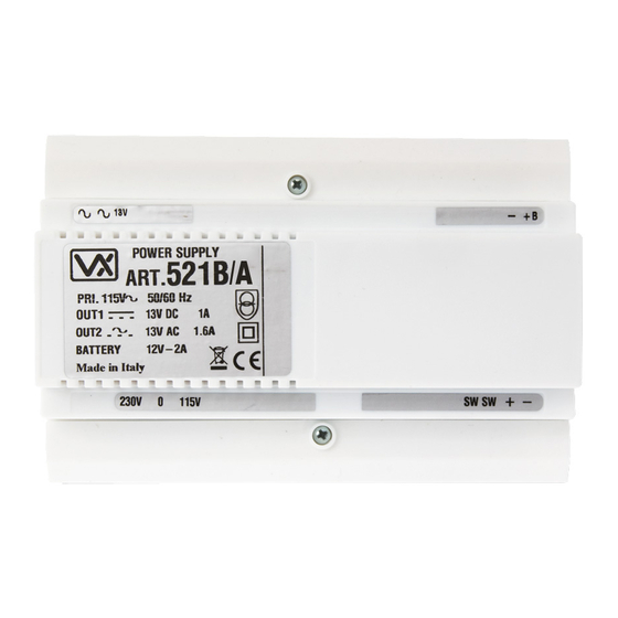
Art. 521B/A
A
13V
POWER SUPPLY
521B
ART.
PRI. 230V
50/60 Hz
OUT1
13V DC
0.8A
OUT2
13V AC
1.6A
BATTERY
12V-2A
Made in Italy
230V
0
A
Fig. 1
DESCRIPTION
Stabilized power supply 13.5Vdc 1A max - 13.5Vac 1A (peak value) with backup battery. Specific for use in digital and access control
systems. It is built in a 9 modules DIN box type A (157.5mm), can be installed on a DIN bar or fixed to the wall by using 2 screws and
screw anchors by the 2 holes diameter = 4.2mm. (Ref.
OPERATION
The power supply Art. 521B can be fed by 230Vac 50/60Hz (115Vac 50/60Hz for Art. 521B/A) mains tension, it has two outputs:
13.5Vdc (between the terminals + and – ) normally used to supply the front panels and 13.5Vac (between the terminals ~ and ~ )
specific for electric locks. For the maintaining of the 13.5Vdc output in case of mains failure, a rechargeable backup battery can be
connected (between the terminals – and +B).
Both Art. 521B and Art. 521B/A includes terminals to connect (between the terminals SW SW) a switch that turns on and off the
output tension 13.5Vdc. If no switch is used between SW SW terminals in is necessary to put a link between these terminals.
In case of mains failure, the back-up battery starts working to keep the output 13.5Vdc constant. The endurance of the battery is
variable according to the type used and to the load connected to this unit. When the tension of the battery decreases more than
15% of its nominal value (battery discharged), the logic controller deactivates the 13.5Vdc output automatically (to avoid battery
depletion). To switch off the system supplied by the Art. 521B or Art. 521B/A, disconnect the 230Vac and turn off (or remove the link)
the switch connected between the terminals SW SW to avoid switching to the battery backup.
CONNECTION TO MAINS
WARNING!
The system must be installed only by a qualified eletrician and in accordance with national rules in force and in-
stallation diagrams (if provided).
In particular we recommend that:
The system is connected to the mains through an all-pole circuit breaker which has a contact separation of at least 3mm
in each pole and shall connect all poles simultaneously;
The all-pole circuit breaker shall be placed for ease of access and the switch shall remain readily operable.
Only for indoor use in dry places. Do not execed the maximum power load indicated.
Art. 521B - 521B/A - Installation instructions
115Vac stabilized power supply
B
Battery
–
13V
+
POWER SUPPLY
521B/A
ART.
PRI. 115V
50/60 Hz
OUT1
13V DC
OUT2
13V AC
BATTERY
12V-2A
Made in Italy
+ –
115V
0
SW
SW
A
Battery
–
0.8A
1.6A
+ –
115V
SW
SW
A
Fig. 1) situated on the base of the box.
A
- 1 -
B
+
Fig. 2
66250110 - V2.1 - 15/04/21
Advertisement
Table of Contents

Related Manuals for Videx 521B


Summary of Contents for Videx 521B
- Page 1 15% of its nominal value (battery discharged), the logic controller deactivates the 13.5Vdc output automatically (to avoid battery depletion). To switch off the system supplied by the Art. 521B or Art. 521B/A, disconnect the 230Vac and turn off (or remove the link) the switch connected between the terminals SW SW to avoid switching to the battery backup.
- Page 2 13Vac +6% -10% 1.6A pulse 13Vac +6% -10% 1.6A pulse (specific for electric locks) (specific for electric locks) 13.5Vdc 0.8A continuous -1AMax 13.5Vdc 0.8A continuous -1AMax - 2 - Art. 521B - 521B/A - Installation instructions 66250110 - V2.1 - 15/04/21...
- Page 3 (tra i morsetti – e +B). Gli alimentatori Art. 521B e 521B/A permettono di collegare (tra i morsetti SW SW) un interruttore di accensione e spegnimento che agisce sulla tensione di uscita 13,5Vdc ma nel caso non si voglia utilizzare l’interruttore inserire un ponticello tra i suddetti morsetti.
- Page 4 13Vac +6% -10% 1,6A impulsivo 13Vac +6% -10% 1,6A impulsivo (specifico per elettroserratura) (specifico per elettroserratura) 13,5Vdc 0,8A continui 1A Max 13,5Vdc 0,8A continui 1A Max - 4 - Art. 521B - 521B/A - Istruzioni di installazione 66250110 - V2.1 - 15/04/21...
- Page 5 - 5 - 66250110 - V2.1 - 15/04/21...
- Page 6 - 6 - 66250110 - V2.1 - 15/04/21...
- Page 7 DISPOSAL In accordance with the Legislative Decree no. 49 of 14 March 2014 “Implementation of the Directive 2012/19/EU on waste electrical and electronic equipment (WEEE)”. The crossed-out bin symbol on the equipment or on the packaging indicates that when the product reaches the end of its lifetime, it must be collected separately from mixed municipal waste.
- Page 8 MANUFACTURER VIDEX ELECTRONICS S.P.A. FABBRICANTE Via del Lavoro, 1 FABRICANT 63846 Monte Giberto (FM) Italy FABRICANTE Tel (+39) 0734 631669 FABRIKANT Fax (+39) 0734 632475 www.videx.it - info@videx.it FABRICANTE ال� ش كة المص ن ِّ عة CUSTOMER SUPPORT VIDEX ELECTRONICS S.P.A.
Need help?
Do you have a question about the 521B and is the answer not in the manual?
Questions and answers