Advertisement
Quick Links
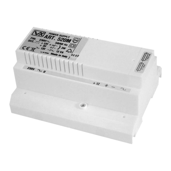
Art.521B
descrIptIon
Stabilized power supply 13.5Vdc 1Amax - 13.5Vac 1A (peak value)
with backup battery. Specific for use in digital and access control
systems. It is built in a 9 modules DIN box type A (157.5mm), can
be installed on a DIN bar or fixed to the wall by using 2 screws
and screw anchors by the 2 holes diameter = 4,2mm. (Ref.A Fig.2)
situated on the base of the box (Fig.1 Ref.A).
connectIon to maIns and power supply
mountIng InstructIons
The system must be installed only by a competent engineer and
according to national rules in force and installation diagrams
proposed (if provided), in particular we recommend to:
• Connect the system to the mains through an all-pole circuit
breaker which shall have contact separation of at least 3mm in
each pole and shall disconnect all poles simultaneously;
• The all-pole circuit breaker shall be placed for easy access and
the switch shall remain readily operable.
power supply InstallatIon
• Remove the terminal side covers by unscrewing the retaining
screws;
• Fix the power supply to a DIN bar or directly to the wall using two
expansion type screws;
• Switch off the mains using the circuit breaker mentioned above
and then make the connections as shown on the installation
diagrams;
• Check the connections and secure the wires into the terminals;
• Replace the terminal covers and fix them using the relevant
screws;
• When all connections are made, restore the mains.
operatIon
The power supply Art.521B can be fed by 115 or 230Vac 50/60Hz
mains tension, it has two outputs tensions: 13,5Vdc (between the
terminals "+" and "-") normally used to supply the front panels and
13,5Vac (between the terminals "~" and "~") specific for electric
locks. For the keeping of the 13,5Vdc output in case of mains failure,
it allows to connect a back-up rechargeable battery (between the
terminals "-" and "+B"). The Art.521B allow to connect (between
the terminals "SW SW") a switch that turn on and off the output
tension 13,5Vdc. If no switch is used between SW SW terminals in
Art.521B - Installation instructions - Istruzioni di installazione
Installation Instructions
Istruzioni di installazione
B
B
A
A
fig.1
DESCRIZIONE
Alimentatore stabilizzato 13.5Vdc 1Amax - 13.5Vac 1A (di picco)
con batteria tampone. Specifico per l'impiego in impianti
citofonici digitali e sistemi di controllo accessi. È realizzato in
custodia DIN 9 moduli tipo A 157.5mm e può essere installato
su barra DIN (a quadro) oppure fissato a parete tramite 2 viti e
tasselli ad espansione avvalendosi dei 2 fori di diametro 4,2mm
predisposti sulla base della custodia (Fig.1 Rif.A).
COLLEGAMENTO ALLA RETE ELETTRICA
ED INSTALLAZIONE DELL'ALIMENTATORE
La
realizzazione
dell'impianto
esclusivamente da personale qualificato e nel rispetto delle
vigenti normative nazionali e degli schemi di installazione
proposti (se disponibili). In particolare si raccomanda di:
• Collegare l'impianto alla rete elettrica tramite un dispositivo
di interruzione omnipolare che abbia una distanza di
separazione del contatto di almeno 3mm per ciascun polo e
che sia in grado di disconnettere tutti i poli simultaneamente;
• Il dispositivo di interruzione omnipolare deve essere
posizionato in un luogo tale da consentirne un facile accesso
in caso di necessità.
INSTALLAZIONE DELL'ALIMENTATORE
• Rimuovere i coperchi copri-morsetti svitando le relative viti e
tirandoli verso l'alto;
• Fissare l'alimentatore su barra DIN o direttamente a parete
utilizzando 2 viti ed i relativi tasselli ad espansione;
• Togliere la tensione di rete tramite il dispositivo sopra indicato
ed eseguire le connessioni come previsto dagli schemi
proposti (la connessione verso la rete va effettuata in base alla
tensione disponibile 127 o 230Vac).
• Verificare che non vi siano errori di connessione e che i fili
siano ben serrati nei morsetti;
• Inserire a scatto i coperchi copri-morsetti e fissarli tramite le relative viti;
• Eseguiti tutti i collegamenti, dare tensione all'impianto.
fuNZIONAMENTO
L'alimentatore Art.521B accetta tensioni di rete a 115 o 230Vac
50/60Hz e fornisce in uscita di due diverse tensioni 13,5Vdc (tra
i morsetti "+" e "-") normalmente utilizzata per l'alimentazione di
posti esterni e 13,5Vac (tra i morsetti "~" e "~") specifica per serrature
elettriche. Per il mantenimento dell'uscita 13,5Vdc in assenza
di tensione di rete, è possibile collegare una batteria tampone
ricaricabile (tra i morsetti "-" e "+B"). L'alimentatore Art.521B permette
di collegare (tra i morsetti "SW SW") un interruttore di accensione e
spegnimento che agisce sulla tensione di uscita 13,5Vdc ma nel caso
fig.2
deve
essere
eseguita
66250110 - V. 1.0 - 14/03/13
Advertisement

Related Manuals for Videx 521B


Summary of Contents for Videx 521B
- Page 1 • Eseguiti tutti i collegamenti, dare tensione all’impianto. operatIon fuNZIONAMENTO The power supply Art.521B can be fed by 115 or 230Vac 50/60Hz L’alimentatore Art.521B accetta tensioni di rete a 115 o 230Vac mains tension, it has two outputs tensions: 13,5Vdc (between the 50/60Hz e fornisce in uscita di due diverse tensioni 13,5Vdc (tra terminals “+”...
- Page 2 13,5Vdc output automatically (to avoid battery depletion). di controllo disattiva automaticamente l’uscita 13,5Vdc (per evitare To switch off the system supplied by the Art.521B, disconnect the l’esaurimento della batteria). Per spegnere completamente il sistema 230Vac and turn off (or remove the link) the switch connected alimentato dall’...
Need help?
Do you have a question about the 521B and is the answer not in the manual?
Questions and answers