Advertisement
Quick Links
Advertisement

Subscribe to Our Youtube Channel
Related Manuals for Hafco Woodmaster PS-3200

Summary of Contents for Hafco Woodmaster PS-3200
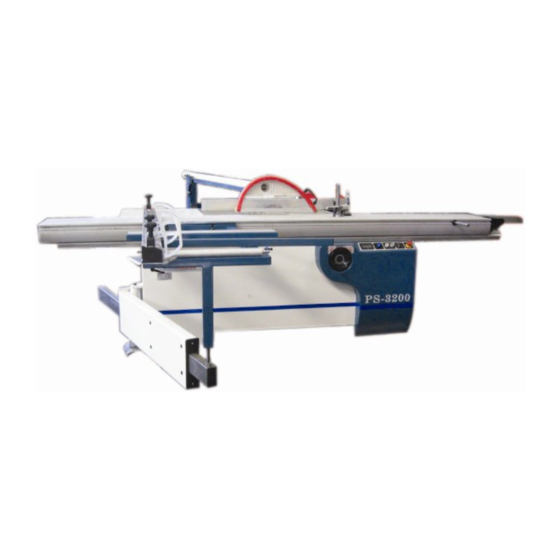
- Page 1 11-3-10 #W724 HAFCO WOODMASTER PS-3200 PANEL SAW ASSEMBLY SET UP INSTRUCTIONS...
- Page 2 Assembly instructions Before un-crating the machine or the table assembly, please ensure the serial numbers on the 2 x crates correspond with each other. If not please contact the point of purchase and advise them serial numbers supplied CAUTION Must be taken when un-crating of sharp edges of sheet metal corner supports and nails Remove lid off the large main saw box (1 of 2 ) and then the sides one by one Remove the lid of the long box (2 off 2) Open rear blue door of the main saw stand to gain access and remove the cardboard box with blades...
- Page 3 Fit sliding table assembly Unpack the long box of all extra pieces leaving sliding table assembly in crate. Remove the 4 sides of the crate With the aid of a forklift remove wrapped sliding table assembly by sliding onto fork tines Carefully cut along length of table and remove packaging.
- Page 4 Tighten the 2 x end screws with 10mm allen key supplied in tool bundle Ensuring first that the table assembly is slid back to sit on the 2 x adjustable table setting screws that have been factory set. Ensure table it against these screw heads (one each end) When these 2 bolts are tight unlock sliding table and slide table all the way to the right...
- Page 5 Fit Overhead Guard Assembly Guard support arm Guard outrigger arm Remove the two bolts out of main base LH rear side (Looking from the front of machine) NB; there are locknuts inside base that need removing first. Fit guard outrigger arm to machine and nip up 2 x screws (Adjustment is needed later) Fit guard support arm onto spigot of arm and locate spring loaded pin into Swivel location engagement bracket.
- Page 6 # Remove the 2 x screws out of the pin that runs through the end of guard support arm. RH screw in Pin of support arm Horizontal slot Guard bush cup Socket head cap screw Remove the blue fiberglass 45degree cutting shield out of guard assembly if fitted.` Remove socket head cap screw out of guard bush cup Fit the guard onto the end of the pipe and refit and fasten tightly the 2 x screws for the pin and the socket head cap screw for the positioning rod...
- Page 7 Also the guard needs to be adjusted 90 deg to table Adjustment is made by unlocking the Nyloc nut on the rear adjustment screw and turning the screw in or out. Guard tilt adjustment screw When guard is 90 degrees lock Nyloc in place NB if the is insufficient adjustment available more adjustment can be obtained by adjusting the draw bar turnbuckle under the sheet metal guard running underside of the guard arm!
- Page 8 Fit rear table extension (560 x 600) to LH side This is held on with 4 x socket head cap screws and can be adjusted up from any fall by screwing in the 4 x lower cap screws as needed and hitting the table were it is bolted on with a soft hammer up and down Sit a straight edge across the main table and sliding table to get extension table were needed Fit Rear table extension (500 x 900) to rear of main table...
- Page 9 Fit sliding rear fence Swivel blade guard out of the way. Rear Fence measurement tape extrusion This pin may have to be pushed down! Rear fence sliding rod When fitting sliding fence casting to rod Ensure lever is in this position as shown Remove the first nut of each of the 3 studs coming off the rear fence sliding rod Leaving 2 thin locknuts locked together on 2 of the studs and 1 x thicker nut on the other with one...
- Page 10 The fence can now be adjusted parallel with this insert if needed by adjusting the 2 inner stud nuts of the fence rod as needed. Ensure the rod is always pulled down on the adjustment screws and lock the second lock nuts tight when setting is achieved The aluminum fence level and parallel can be adjusted if needed by loosening and turning the cams in the sliding casting that the fence slips on.
- Page 11 Slide fence out over onto sheet metal extension table and adjust table as needed Fit fence measure Remove the 3 x M6 socket heads cap screws from above the fence rod and fit the RHS measuring assembly (This will need setting later when blade is put on machine) Fit Push stick mount onto top of sliding casting as shown...
- Page 12 Fit sliding table outrigger frame Swing out outrigger pivot arm. Remove rubber stopper of the end of outrigger extension arm and carefully insert arm with location bolt sticking up, into outrigger assembly. When all the way through refit rubber stopper tightly.
- Page 13 Fit front fence Sit aluminum riser block on outrigger as shown Sit fence on its side as shown and align the 2 x locating pins front and back and the middle lock down bolt as shown. Tilt fence over the right way locating the 3 in perspective holes.
- Page 14 Fit a smaller magnifier line to it ( 3 x magnifying lines found in blade box) Fit the other sliding stop to the main arm and screw on a small magnifying line Fit magnifying sight (large one) to fence extension arm Fit thigh pushing bar Remove plastic plug from end of tube Pushing bar...
- Page 15 Fit Right hand table extension guard as shown Fit work clamp Slide onto end of table and lock in place when needed. Fit blades Extreme care must be taken due to sharp blade teeth. Ensuring machine is not connected to power Slide table assembly all the way back to gain access to blade area Pull lower blade guard assemble open NB blade nuts undo the direction the blade spins in use.
- Page 16 Setting height of Riving Knife The riving knife height can now be set (just under height of blade cut) Put a bit of scrap wood behind main blade and wind blade up level with the top of it. Undo riving knife lock bolt and move riving knife as needed to be just under level of wood Lock bolt tight...
- Page 17 Ensuring machine is not connected to power Set measurement of tape on rear fence Bring the fence 100mm away from blade measuring it with a tape measure as shown. Loosen the tape adjustment screw found under the RH end on the alloy extrusion the tape is set in Slide the tape in the extrusion to show 100mm under the fence and then tighten the screw again.
- Page 18 Putting power to machine and testing operation Blade Angle LED Emergency Stop Button Only Do not use to turn blades off in general use Power on Light Main blade On/Off Scouring blade On/Off switch Reset button to Buttons Will only operate when main blade is Zero DRO turned on.
- Page 19 Blade guard Please note the saw is supplied with 2 different rear covers for the blade guard. A 45 degree one that must be fitted when tilting the blade and one that is for straight cutting Ensure the correct guard is used at all times. Guard for 90 degree Guard for tilted blade Setting scouring blade.
- Page 20 Changing main blade speeds The main blade has two speeds Low 3800 RPM ( Belts on Pulley blade side ) High 5600 RPM (Belts on Pulley Motor Side) To change speeds wind the blade all the way down and tilt it to 30 degrees ( This will give you easier access to change the belt ) Disconnect the power from the machine and open the rear door to the machine base...
- Page 21 Fixed table and supporting & adjustment mechanism guide track fix e d ta b le p ro te c tio n b o a rd 21, bolt lift b o a rd 22, pipe block dust collection pope c o n n e c tio n b o a rd th e c o v e r o f a n ti-d u s t 2 4 , g u id e tr a c k...
- Page 22 Main saw motor base spindle pressure cushion m o t o r main spindle sheath m o t o r b a s e b e a r i n g c u s h i o n pressure cushion connection board main spindle adjusting sheath...
- Page 23 Auxiliary saw 16, inching handle 29, scoring saw spindle 17, lock nut 30, bearing fixed sheath 31, scoring saw sheath 20, fixed base 32, bearing 33, sheath 21, feeding block 22, bolt 34, driving belt 23, scorning saw turning base 35, scoring saw wheel 24, spring 36, pressure cushion...
- Page 24 Machine body & turning arm machine body adjusting spindle hair brush door cover stop head bolt roll wheel urgent stop switch bearing board base operation button bearing spindle of turning arm hair brush sheath the pipe of turning arm eccentric spindle...
- Page 25 Bracket Plug Adjustment axle Holding plate Limit shaft Reinforcing plate Seat board V- groove Screw Stabilizer nail Stud Ejector block Lock block Clip Bracket Screw Shaft Carriage roller Bearing Eccentric shaft Handle Plug Support Screw Platen Revolving shaft handle Angle scale seat Angle scale Pad board Screw...
- Page 26 Crosscut guide plate Adjustment bole 18. S cr ew 36. Pad Fixing bolt 19. Magnifier 3 7 . Holding plate 20. Fixing block Locking handle 3 8 . Pad 21. S c r e w b o l t 3 9 . S c r e w 22.
- Page 27 Straight-cut guide plate Straight-cut guide plate Idler wheel Cam seat (guide plate seat) Spacing sleeve Cam axle (guide shaft axle) Push handle Push handle seat Supporting bolt Screw Screw cap Handle Screw cap Handle shaft Lock plate Eccentric shaft Board Clip Screw Shaft...
-
Page 28: Sliding Table
Sliding table S l i d i n g t a b l e S c r e w S c r e w H a n d l e Handle terminal plate Locking handle Locatin g plate F i x i n g b l o c k S c r e w 1 0 . - Page 29 9 Sliding track seat track seat s c r e w adjustment screw bolt keeping bracket steel ball lock plate connecting strip track metal strip...
Need help?
Do you have a question about the PS-3200 and is the answer not in the manual?
Questions and answers