Table of Contents
Advertisement
Quick Links
Advertisement
Table of Contents
Troubleshooting

Subscribe to Our Youtube Channel
Related Manuals for AGRI TRONIX Brecknell SBI-521 Series

Summary of Contents for AGRI TRONIX Brecknell SBI-521 Series
- Page 1 SBI-521 Indicator Series Service Manual AWT35-500811 Issue AF January 2013...
- Page 2 © Brecknell, LLC 2013. All rights reserved. No part of this publication may be reproduced, stored in an electronic retrieval system, or transmitted in any form or by any means, electronic, mechanical, photocopying, recording or otherwise without the prior written consent of the copyright owner, or as permitted by law or under license.
-
Page 3: Table Of Contents
Table of Contents Manual revision history ..........................4 Chapter 1 General information and warnings ..................5 About this Manual ......................5 Text Conventions ......................5 Special Messages ....................... 5 Warnings ..........................6 Installation .......................... 6 Charge the Battery ...................... 6 Connections ........................ - Page 4 Output Data ....................... 24 Display Gross or Net Weight ..................24 Change Weight Unit ....................24 Check Weight ......................26 Navigating the Count Mode ..................... 26 Enter Count Mode ..................... 27 Obtain Piece Weight ....................27 Check Counts (counts compare) in Counting mode: ..........28 Percent Weigh Mode .......................
- Page 5 Chapter 7 Legal for Trade ........................68 Configuration/Calibration Switch ..................68 Audit Trail Parameters ..................... 69 View Configuration Counter ..................69 View Calibration Counter ................... 69 Chapter 8 Troubleshooting ........................70 Display Characters ......................70 Display Symbols ......................71 Error Messages and Troubleshooting ................72 Addendum 1: Quick Setup and Configuration ..................
-
Page 6: Manual Revision History
Manual revision history Current Date Created Details of Changes Issue November 2012 previous revision 1.3 done as a Word document. Issue AD has been converted to FrameMaker. Legal for Trade chapter and addendum 1 and 2 were added. January 2013 update menu tables with added parameters and LED font. -
Page 7: Chapter 1 General Information And Warnings
General information and warnings 1.1 About this Manual This manual is divided into chapters by the chapter number and the large text at the top of a page. Subsections are labeled as shown by the 1 and 1.1 headings shown above. The names of the chapter and the next subsection level appear at the top of alternating pages of the manual to remind you of where you are in the manual. -
Page 8: Warnings
1.2 Warnings Avoid lengthy exposure to extreme heat or cold. Your scale works best when operated at normal room temperature. Always allow the scale to acclimate to a normal room temperature before use. Allow sufficient warm up time. Turn the scale on and wait for a few minutes if possible. -
Page 9: Connections
CAUTION: Danger of explosion if battery is incorrectly replaced. Replace only with the same or equivalent type recommended by the manufacturer. Dispose of used batteries according to the manufacturer’s instructions. ATTENTION: Il y a danger d'explosion s'il y a remplacement incorrect de la batterie, remplacer uniquement avec une batterie du même type ou d'un type équivalent recommandé... -
Page 10: Weigh Platform Or Loadcell Connections
Figure 1.2 Main Board 1.4.1 Weigh Platform or Loadcell Connections Connect the loadcell cable to the loadcell connector on the main board. Connection assignments for the loadcell connector are shown in Figure 1.3. Refer to Table 1.2 page 9 for loadcell jumper configuration. Figure 1.3 Loadcell Connector Table 1.1 Loadcell Connections Board... -
Page 11: Rs-232 Serial Port Connections
Loadcell Jumper Set JP3 jumpers for either a 4-wire or 6-wire loadcell. Table 1.2 Loadcell Jumper Connector(JP3) Connected Pins Function 4 wire loadcell is used 6 wire loadcell is used 1.4.2 RS-232 Serial Port Connections The SBI-521 indicator comes standard with two full Bi-directional RS-232 serial ports designed for connection to either a PC or a serial printer. -
Page 12: Rs-485 Serial Port Connections
1.4.3 RS-485 Serial Port Connections The SBI-521 indicator comes standard with one RS-485 network port designed for local networks and multidrop communication links. Refer to Table 1.10 Table 1.11 page 12 for COM2 jumpers. Figure 1.5 RS-485 Connection Table 1.4 RS-485 Port Connections Designation Description Electrical Level... -
Page 13: Sockets And Jumpers
1.5 Sockets and Jumpers Figure 1.6 shows main board connectors for the loadcell, printer or computer, power supply and battery.. Figure 1.6 SBI-521 Main Circuit Board 1.5.1 Definition of Sockets and Jumpers Table 1.8 ADP - Adapter Power Input Connector Pin # Definition In/Out/Power... -
Page 14: Communication Jumpers
1.5.2 Communication Jumpers Jumpers on JP8. RXD2 and TXD2 will need to be set to the desired configuration. Table 1.10 JP8 Connector Connected Pins Function COM2 is used as RS-232 COM2 is used as RS-485 COM2 is not used COM2 is not used Table 1.11 RXD2 and TXD2 Jumper Connectors Connected Pins Function... -
Page 15: Routine Maintenance
1.6 Routine Maintenance IMPORTANT: This equipment must be routinely checked for proper operation and calibration. Application and usage will determine the frequency of calibration required for safe operation. Always turn off the machine and isolate from the power supply before starting any routine maintenance to avoid the possibility of electric shock. -
Page 16: Chapter 2 Specifications
Specifications 2.1 SBI-521 Series Models Model Description SBI-521 LED Version, 6V4.0AH lead-acid rechargeable battery is installed SBI-521 LCD version, 6V4.0AH lead-acid rechargeable battery is installed 2.2 Housing and Outline Dimension 2.2.1 Housing IP65 wash-down stainless steel housing with rotary bracket. 2.2.2 Outline Dimension With bracket: 10.31"... -
Page 17: Power Supply
2.3 Power Supply 100 - 240 VAC, 50/60 Hz AC adapter 6V 4.0AH lead-acid rechargeable battery Battery charging Circuit: built-in Model Working Current ≤ SBI-521 100mA (use battery, no load-cell, no adaptor, LED.BRT is set to 2) ≤ SBI-521 45mA (use battery, no load-cell, no adapter, backlight is on) 2.4 Display SBI-521: 7-digits,7-segment, 0.7'' (17mm) ultra brightness LEDs with 16 annunciators... -
Page 18: Communication
2.5 Communication Serial port1 Full-duplex RS-232 Serial port2 Full-duplex RS-232 or half-duplex RS-485 Baud Rate Selectable: 1200-2400-4800-9600-19200-22800/38400-57600 bps Data Output Format 8N1, 7O1, 7E1 Protocol programmable 2.6 Analog Circuitry 24-bit A/D converter Conversion Speed: 10Hz or 80Hz Input range: -15mV to +15mV Output code:1mV input between S+ and S- of loadcell connector will output about 100,000 raw counts Hardware low pass filter and 2 programmable digital low pass filters... -
Page 19: Real Clock
2.11 Real Clock Built-in nonvolatile real time & date 2.12 Other Main Functions Programmable zero range Programmable pre-set tare weight Programmable automatic zero point tracking Programmable motion detection window Programmable auto-power off time, backlight working mode (LCD version) and adjustable LED brightness (LED Version) Programmable hold function with peak weight holding and dynamic weighing Available check weighing mode Available parts counting mode... -
Page 20: Chapter 3 Configuration
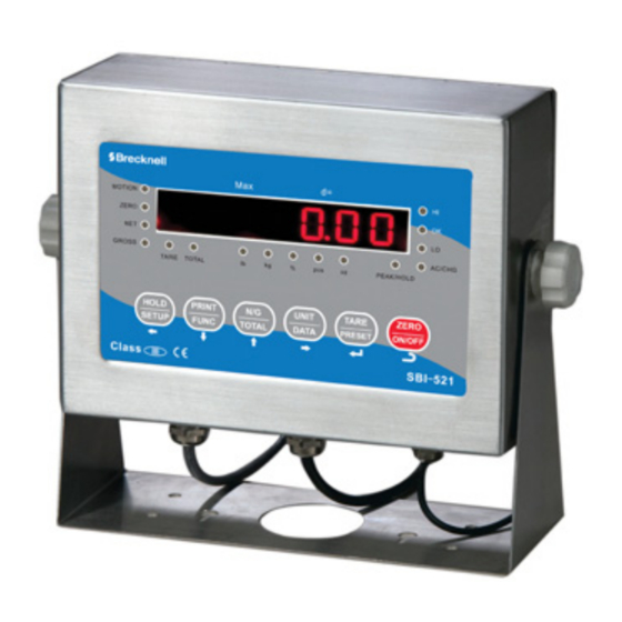
Configuration To set up the indicator, you must first enter the appropriate menu mode. The front panel keys become directional navigators to move around in the menus. See Table 3.3 details. 3.1 Front Panel The front panel incorporates the display and keypad. 3.1.1 LED Version Brecknell Class III... -
Page 21: Lcd Version
3.1.2 LCD Version Brecknell lb:oz PeakTotalNET Hold Class III 3.2 Display The Model SBI-521 indicator utilizes a 6-digit LCD (Liquid Crystal Display) or a 7 -digit LED display providing the weight and system information. 3.2.1 LED The annunciators used with the LED model surround the display. The annunciator will be lit went the mode is active. -
Page 22: Lcd
Table 3.1 LED Display Annunciators and Definitions LED Annunciator Description ZERO Better known as the "Center of Zero" annunciator. It is lit whenever the displayed weight is within ± 0.25 divisions of true zero. MOTION Illuminates when weight is within motion band. PEAK/HOLD (1) flashing/not flashing: working HOLD mode and displaying number is/isn't live (2) red/green: working in HOLD mode and HOLD type is/isn't PEAK-HOLD. -
Page 23: Keyboard
Table 3.2 LCD Display Annunciators and Definitions LCD Annunciator Description Better known as the "Center of Zero" annunciator. It is lit whenever the displayed weight is within ± 0.25 divisions of true zero. Illuminates when weight is within motion band. Hold Flashes when hold key is pressed. - Page 24 Table 3.3 Function of the Keys Mode Condition Function Weigh, count or percent Press for less than 3 seconds Enter or exit HOLD mode Weigh, count or percent Press for more than 3 seconds Enter setup mode Input data Press for more than 3 seconds Input decimal point Input data Press for less than 3 seconds...
-
Page 25: Navigating The Weigh Mode
3.4 Navigating the Weigh Mode 3.4.1 Change the Working Mode Press the [FUNC] key for 3 seconds. Use the [FUNC] key to choose and confirm entry into weighing mode, counting mode or percentage working mode. The count and/or percentage mode must be set to yes in the FUNC menu within the setup mode. Otherwise the indicator will only show the weighing mode. -
Page 26: Output Data
Table 3.4 Zero and Tare Limitations key function Weight on Data in TARE Standard platform memory unit Tare key Zero key ≤0 No action Zero Clear the tared weight >0 Tare Canada ≤0 No action Zero Clear the tared weight >0 Tare No action... - Page 27 Table 3.5 Use kg as Primary Unit Display Division Value Calibration Division Value lb:oz 0.0001kg 0.0001kg 0.0002lb Not available 0.001kg 0.001kg 0.002lb Not available 0.01kg 0.01kg 0.02lb 0.5oz 0.1kg 0.1kg 0.2lb Not available Not available 10kg 10kg 20 lb Not available 0.0002kg 0.0002kg 0.0005 lb...
-
Page 28: Check Weight
Display Division Value Calibration Division Value lb:oz 0.005 lb 0.002 kg 0.005 lb 0.1 oz 0.05 lb 0.02 kg 0.05 lb 1 oz 0.5 lb 0.2 kg 0.5 lb Not available 5 lb 2 kg 5 lb Not available 50 lb 20 kg 50 lb Not available... -
Page 29: Enter Count Mode
3.5.1 Enter Count Mode To enter counting mode press the [FUNC] key for more than 3 seconds. WEIGH will be displayed. Use the [N/G] or [PRINT] key to select COUNT. Press [TARE] to confirm the parts counting mode. The pcs annunciator will be illuminated. -
Page 30: Check Counts (Counts Compare) In Counting Mode
If the calculated piece weight is less than 0.5d, the indicator will display PWt. E r and go back to counting mode. Otherwise, after the reasonable piece weight has been captured, the scale will go back to counting mode. The piece weight will be saved and used again. -
Page 31: Obtain Percentage Weight
In percent weigh mode, the function of [ZERO], [TARE], [PRINT], [HOLD], [TARE], [N/G], [SETUP], [ON/OFF] keys are available. 3.6.2 Obtain Percentage Weight There are two ways to obtain the unit percent weight. Input Weight and Percentage The scale calculates the unit-percentage weight and weigh samples weight which percentage is known. -
Page 32: Check Percent (Percentage Compare) In Percent Weighing Mode
After INP. P CT is shown, 000000 (position of decimal point is determined by CONFIG-FUNC-PERCEN setting) will be displayed Use the [PRINT], [N/G], [UNIT] keys to input the percentage of samples. Press the [TARE] key to confirm. If the calculated unit-percentage-weight is less than 0.5d, the indicator will display Pct. -
Page 33: Activate The Hold Function
3.7.1 Activate the Hold Function The CONFIG-FUNC-HOLD menu item must be set to YES. Menu items of USER-HOLD-HLD.MOD /-AVG.TIM /-HLD.TIM /-DYN.RNG /-STB.TIM, USER-OTHER-NLD.RNG need be set to reasonable value. To speedup sampling of weight, set USER-HOLD-AD.H.SPD menu item to YES. 3.7.2 Access the Hold Mode To enter the HOLD mode, press the [HOLD] key while in the normal weighing mode, counting mode or percent weighing mode. -
Page 34: Hold Annunciators
To exit HOLD mode, press the [HOLD] key again. If the time of scale being unstable is more than USER-HOLD-STB, TIM, STB. E R will be shown. Press the [TARE] key to start averaging again or press the [HOLD] key to exit. Average HOLD Set the USER-HOLD-HLD.MOD parameter to AVERAG. -
Page 35: Enable Data Compare Function
3.8.1 Enable Data Compare Function To make data compare function be available, CONFIG-FUNC-COMPAR menu item should set to YES, and high and low limitation should be set correctly according to following steps: 3.8.2 View Data Compare Function From the weighing, counting or percent weighing mode, press the [DATA] key more than 3 seconds to enter input compare data of high and low mode. -
Page 36: Enable Accumulation
3.9.1 Enable Accumulation To make the accumulation function be available the CONFIG-FUNC-ACCUMU parameter should be set to MANUAL or AUTO. Manual Accumulation When CONFIG-FUNC-ACCUMU is set to MANUAL, the stable and positive displayed net weight must be larger than the USER-OTHER-NLD.RNG setting. Piece or percentage can be accumulated by a long press of the [TOTAL] key. -
Page 37: Display And Set Date
Time display Format is: txx.xx.xx(hh-mm-ss) for LED Version, 24h format xx:xx:xx(hh-mm-ss) for LCD Version, 24h format. Press the [DATA] key for 3 seconds. The first digit of the time will flash. Use the [PRINT] or [N/G] key to enter the first digit. If time of no operation is more than 5s, it will automatically exit modification mode. -
Page 38: Display Interface Type Of Com2
3.13 Display Interface Type of COM2 This function is used only to check whether the hardware and software about COM2 are matched. Enter the Setup Mode by pressing the [SETUP] key more than 3 seconds. Use the [PRINT] or [N/G] key to select the MISC menu. Press [TARE] to select the MISC menu. -
Page 39: Serial Port1/2 (Com1/2) Receiving Test
3.16 Serial Port1/2 (COM1/2) Receiving Test Before testing the receiving function of COM1 or COM2, a cable is need to connect a computer to the indicator. A terminal program such as Hyper Terminal is also needed for testing. Note: baud rate is selected by USER-COM1/2-BAUDRT, 8N1 byte format is fixed, Hex data (0x00 - 0xff) are used. -
Page 40: Chapter 4 Setup Mode
Setup Mode The setup menu consists of five different sub-menus. Within each sub-menu are different menu options. The config/cal switch must be set in the ON position in order to make changes to specific parameters. 4.1 Entering the Setup Menu Power on the indicator by pressing and holding the [ON/OFF] key. - Page 41 Table 4.1 Key Navigation [HOLD/SETUP] Access the Setup Menu. [PRINT/FUNC] Scroll through available menus. Choose a sub-menu Make a change within the sub-menu [NG/TOTAL] Scroll through available menus. Choose a sub-menu Make a change within the sub-menu [UNIT/DATA] Choose a sub-menu [TARE/PRESET] Make a change within the sub-menu [ZERO/ON/OFF]...
-
Page 42: Setup Menu Parameters
4.3 Setup Menu Parameters This section provides more detailed descriptions of the selections found in the Setup Menu. The menu charts show the flow of the parameters and also provide a quick reference to the parameters withing the menu. The menu tables show the submenus, options and default parameter in LED/LCD display format to coinside with the actual display. - Page 43 Table 4.2 CONFIG Menu Choices and Explanations CONFIG SubMenu1 SubMenu2 Option Default Parameter Description Comment CFG. O N Seal switch position The display will show whether the CFG. O FF seal switch is in the ON or Off position. This parameter can’t be changed within the software.
- Page 44 CONFIG SubMenu1 SubMenu2 Option Default Parameter Description Comment 10N. D SP Display weight at 10 *If (REGULA)= none this times division number parameter will not be available. T under primary unit UNITS Units key 0=kg 1=lb 2=lb:oz 3= kg,lb 4=kg,lb:oz 5=lb,lb:oz 6=kg,lb,lb:oz MOTION...
- Page 45 CONFIG SubMenu1 SubMenu2 Option Default Parameter Description Comment FILTER FLT1. T H 0-255 Digital filter1 threshold: 0=no filter1 1-254=filter1 used only when vibration in ±0.5d*(1-254) 255= filter1 be always used FLT1. S T 1-64 Digital filter1 intensity 1-64 ADC’s data will be averaged FLT2.
-
Page 46: User Menu
4.3.2 User Menu RESET COM1 OUT1 SCAL.ID GROSS TARE PERCNT UPCTWT COUNT BAUD.RT BYT.FMT OUT.MOD LAYOUT PCWT ACCUM DATE TIME AD.CODE BAT.VOL STATUS B.LINE 1200 2400 4800 9600 19200 38400 57600 MULTPL SINGLE 200S 200F NONE LINE1 LINE2 LINE3 LINE4 CONT PRINT PRT.CMD... - Page 47 Table 4.3 User Menu Choices and Explanations USER SubMenu1 SubMenu2 Option Default Parameter Description Comment RESET Reset User menu parameters to default setting COM1 BAUD. R T 1200 9600 Select COM1 baud rate 2400 4800 9600 19200 38400 57600 BYT. F MT Select COM1 byte format (1)8N1=8 data bits, No parity check bit, 1 stop bit...
- Page 48 USER SubMenu1 SubMenu2 Option Default Parameter Description Comment OUT1 SCAL. I D Enable or disable scale ID Prompt is "SCALE ID" number GROSS Enable or disable gross weight Prompt is "GROSS" TARE Enable or disable tare weight Prompt is "TARE" Enable or disable net weight Prompt is "NET"...
- Page 49 USER SubMenu1 SubMenu2 Option Default Parameter Description Comment COM2 BAUD. R T 1200 9600 Select COM2 baud rate 2400 4800 9600 19200 28800 57600 BYT. F MT Select COM2 byte format (1)8N1=8 data bits, No parity check bit, 1 stop bit (2)7O1=7 data bits, 1 Odd parity check bit, 1 stop bit (3)7E1=7 data bits, 1 Even parity...
- Page 50 USER SubMenu1 SubMenu2 Option Default Parameter Description Comment OUT2 SCAL. I D Enable or disable scale ID Prompt is "SCALE ID" number GROSS Enable or disable gross weight Prompt is "GROSS" TARE Enable or disable tare weight Prompt is "TARE" Enable or disable net weight Prompt is "NET"...
- Page 51 USER SubMenu1 SubMenu2 Option Default Parameter Description Comment BEEP Enable or disable beep after a key is pressed. COMPAR NONE IN. L MT (1)NONE = no beep L. L OW (2)L.Low = beep when lower than low limitation; IN. L MT (3)IN.LMT = beep when in range of low and high limitation O.
- Page 52 USER SubMenu1 SubMenu2 Option Default Parameter Description Comment HOLD HLD. M OD NONE AUTO Hold mode (1)NONE=no hold function PS. P EAK (2)PS.PEAK=Positive Peak number Hold mode. Scale will display and refresh the positive peak value from last zero setting. NG.
- Page 53 USER SubMenu1 SubMenu2 Option Default Parameter Description Comment OTHER NLD. R NG 1-255 1-255=the range of weight is 1- 255d. When current weight is less than this value, the scale can be regarded as empty, or the load on scale is removed. It must be bigger than (CONFI.MOTION).
-
Page 54: Cal Menu
4.3.3 Cal Menu CAL.ON ZERO LINE INPUT CAL.END CAL.OFF CAL.PO CAL.P1 END.Y CAL.P2 END.Y CAL.P3 Figure 4.3 CAL Menu Chart The figure above is an illustration of the available menus with the CAL menu and the choices within those menus. Refer to Table 4.4 for explanations of the menu choices. -
Page 55: Misc Menu
4.3.4 Misc Menu CODE DATE TIME COM2.TY Figure 4.4 MISC Menu Chart The figure above is an illustration of the available menus with the MISC menu. There are no programming choices within this menu. Refer to Table 4.5 for explanations of the menu choices. -
Page 56: Exit The Setup Menu
4.4 Exit the Setup Menu Power off the indicator by pressing and holding the [ZERO/off] key. Move the slide switch on the rear cover back to the left and replace the metal protective plate. Refer to section for location. Turn the indicator back on by pressing the [ON] key. The display will go through a digit check, then settle into Normal Operating mode. -
Page 57: Chapter 5 Calibration
Calibration The config/cal switch must be set to the ON position in order to calibrate the indicator. NOTE: More than 10% of the full scale weight is needed for calibration. 5.1 Calibration Mode Access the setup mode by pressing the [SETUP] key for 3 seconds. Use the [PRINT] key to select the CAL menu. -
Page 58: Weight Fine-Tune
Press the [TARE] key to confirm the calibration. The indicator will flash the input standard weight. When the weight becomes steady the indicator will automatically go to next step. If this point can't be calibrated correctly CAL. E r will be displayed. It is possible the weight load onto scale is too small or the input data is incorrect. -
Page 59: Display Adc Output Code
5.3 Display ADC Output Code In this mode, you can examine the stability of weighing system and increment the ADC output code corresponding to the loaded weight. Note: The increment of ADC code for full scale weight must be larger or equal to 10 times of selected display division. - Page 60 If the voltage is not correct Calibrate the voltage according to following steps: Prepare a DC power supply which output voltage can be adjusted from 5V to 8V (output current must be larger than 0.5A). Power off the indicator and unplug the AC adaptor.
-
Page 61: Chapter 6 Serial Communication
Serial Communication 6.1 Com Port 1 COM1 is a RS-232 bid-directional port. Communication wires are connected to the RS- 232 connector using TXD1, RXD1 and GND. Refer to page 9 for connection details. 6.2 Com Port 2 COM2 can be RS232 or RS485, if used as RS232, communication wires come from RS232 connector, and TXD2, RXD2 and GND are used, if used as RS485, communication wires come from RS485 connector, and A and B are used (if need GND or +5VCC1 can be used). - Page 62 Table 6.1 Symbols Used <LF> Line Feed character (hex 0AH) <CR> Carriage Return character (hex 0DH) <ETX> End of Text character (hex 03H) <SP> Space (hex 20H) Four current status bytes <P> Polarity character: "?" or " " W 1---W6 Reading data, 1-6 bytes (six digits) <DP>...
-
Page 63: Commands And Response
6.5 Commands and response Set the USER-Com 1/2-LAYOUT parameter 6.5.1 Single Command: W<CR> (57h 0dh), request current reading Response <LF>^^^^^^^^U <CR><LF> H <CR><ETX>---over capacity <LF>_ _ _ _ _ _ _ _ U <CR><LF> H <CR><ETX>---under capacity <LF> - - - - - - - - U <CR><LF>... - Page 64 Command: U<CR> (55h 0dh) Response Changes units of measure (simulate UNIT key) and return scale status with new units, The new measure unit should be allowed to use <LF> U <CR><LF> H <CR><ETX> Command: L<CR> (4ch 0dh) Response If Hold function can be activated, it will enable/disable hold function (simulate HOLD key) and returns scale status. <LF>...
-
Page 65: Multiple
6.5.2 Multiple Output string frame <LF><Add><Prompt><p>W <Dp>W <CR> ---- Line number and content are determined by setting of USER-OUT1/2-xxxx <LF><Add><Prompt>H <CR> ---- USER-OUT1/2-STATUS is set to YES <LF><Add><CR> --- USER-OUT1/2-LINE is set to LINE1/2/3/4 ---The number of blank lines is determined by USER-OUT1/2-LINE setting <ETX>... -
Page 66: Config-Ad.from=Com2
Counting Mode: SCALE ID: 123456 GROSS: 1234.55kg TARE: 12.15kg NET: 1222.40kg QUANTITY: 24448pcs PIECE WT: 0.05kg ACC. N: TOTAL: 23456pcs DATE: 2011-06-12 TIME: 12:34:56 A/D CODE: 1234345 VOLTAGE: 6.7V STATUS: bpq2 Percent weighing mode: SCALE ID: 123456 GROSS: 12345lb TARE: 10lb NET: 12335lb... -
Page 67: Communication When User-Com1/2-Layout Is Set To 200S/200F
The data frame format from COM2 is: <CR><LF><STX><STH><STL><W1H><W1L><W2H><W2L><W3H><W3L><ETX> Total 12 bytes are in a frame string. W1W2W3 is 24bits output raw counts from ADC (Hex format), (ST) is status byte, <XXH>is its high order 4 bits of XX and <XXL> is its lower order 4bits of XX Status byte definition: 0= in working... - Page 68 Note: When Units = lb:oz, response: <STX><POL>xxxLxx.xO<G/N><STAT><CR><LF> Or <STX><POL>xxxxxLxxO<G/N><STAT><CR><LF> Figure 6.2 Set for 200F Note: When Units = lb:oz, response: <STX><POL>xxx<SP>lb<SP>xx.xoz<SP><GR/NT><CR><LF> Or <STX><POL>xxxxx<SP>lb<SP>xxoz<SP><GR/NT><CR><LF> Command: Z<CR> (5ah 0dh) Response: Zero function is activated (simulate ZERO key). The indicator will not respond if the scale is in motion, positive overload or negative overload. The indicator will also not respond if it is not in gross mode or within the zero range specified in the Setup Menu.
- Page 69 Command: N<CR> (4eh 0dh) Response: This command is sent to the indicator to revert to gross mode. The indicator will not respond if the scale is in motion, positive overload or negative overload. The indicator will also not respond if it is not in gross mode or a tare has yet to be established.
-
Page 70: Chapter 7 Legal For Trade
Legal for Trade The Model SBI-521 must be configured to meet regulations mandated by local weights and measures authorities. 7.1 Configuration/Calibration Switch The configuration/calibration switch is used to protect the indicator from being configured or calibrated under legal for trade conditions. When set to legal for trade and sealed with a lead seal, the indicator can only be configured and calibrated by authorized personnel. -
Page 71: Audit Trail Parameters
7.2 Audit Trail Parameters Two separate incrementing, non-resetable audit trail parameters are used by the Model SBI-521 to indicate changes to various parameters or calibration. 7.2.1 View Configuration Counter Press and hold the [SETUP] key for 3 seconds. CONFIG is displayed Press the [TARE] key. -
Page 72: Chapter 8 Troubleshooting
Troubleshooting This chapter gives explanations on commonly seen errors, display characters and display symbols. 8.1 Display Characters ASCII LCD/LED ASCII LCD/LED ASCII LCD/LED SBI521 Service Manual... -
Page 73: Display Symbols
8.2 Display Symbols Symbol Description 0------ Zero is over the setting range 0_______ Zero point is below the setting range Ad------ Signal to ADC is over maximum range Ad______ Signal to ADC is below minimum range -------- Weight is over upper limitation or display data is over limitation ________ Weight is below lower limitation EEP. -
Page 74: Error Messages And Troubleshooting
8.3 Error Messages and Troubleshooting Symptom Probable Cause Remedy Ad------ Loadcell wires to indicator are incorrectly Make sure wires are ok and correctly connected. connected, shorted, opened, ADC or loadcell(s) Replace loadcell or ADC chip, Service required. Ad______ are damaged. 0------ Weight reading exceeds Power On Zero limit. -
Page 75: Addendum 1: Quick Setup And Configuration
Addendum 1: Quick Setup and Configuration 9.1 Configure the SBI-521 to a Floor Scale 9.1.1 Setting the Capacity and Count by Refer to the next page for wiring and of sense line jumpers placement. Press the [HOLD/SETUP] key for 3 seconds. The indicator shows Config to indicate that you are in Setup Menu mode. -
Page 76: Loadcell Connection And Jumpers
The display will cycle power. After the indicator reboots, the display will show the software version and capacity followed by the weighing mode. 9.1.2 Loadcell Connection and Jumpers Table 9.2 Loadcell Jumper Connector(JP3) Connected Pins Function 4 wire loadcell is used 6 wire loadcell is used Table 9.3 Loadcell Terminal Block (typical Brecknell color code) Wire Color... - Page 77 4-wire jumper configuration Figure 9.2 Loadcell Jumper Location SBI521 Service Manual...
-
Page 78: Addendum 2: Sbi-521 Calibration
Addendum 2: SBI-521 Calibration Access the setup mode by pressing the [HOLD/SETUP] key for 3 seconds. The indicator shows Config to indicate that you are in Setup Menu mode. Press the [PRINT] key to select the CAL menu. Press the [TARE] key to enter the calibration menu. After entering this mode, the number of calibrations will be shown first. - Page 79 15b. If no is selected, it will go to the next step. When first default standard weight is displayed after Cal. P 3 being shown. The default standard weight is 100% of full scale. Use the [HOLD], [PRINT], [N/G], [UNIT] keys to input the value of the loaded weight (more than 10% of full scale weight and larger than the weight used on CAL.P2) onto scale Press the [TARE] key to confirm.
-
Page 80: Addendum 3: Drum Weigher Setup
Addendum 3: Drum Weigher Setup Turn on the indicator and go in to the Config setting by pressing and holding down the [SETUP] key until CONFiG is displayed. Press the [TARE] key and the display will show CFG. ON. If CFG.OFF is displayed, move the seal switch under the triangle plate on the back panel. - Page 82 Brecknell USA 1000 Armstrong Dr. Fairmont MN 56031 Tel:507-238-8702 Fax:507-238-8271 Email: sales@brecknellscales.com http://www.brecknellscales.com Brecknell UK Foundry Lane, Smethwick, West Midlands, England B66 2LP Tel:+44 (0) 8452 46 6717 Fax:+44 (0) 8452 46 6718 Email: sales@brecknellscales.co.uk http://www.brecknellscales.com...
Need help?
Do you have a question about the Brecknell SBI-521 Series and is the answer not in the manual?
Questions and answers