Advertisement
Quick Links
INSTALLATION AND MAINTENANCE INSTRUCTIONS
SMB600 Surface Mounting Kit for Use
with 400 or 500 Series Detectors with
6"/152.4mm Dia. Base, 400 Series
Direct-Wire Detectors and Sounder Bases
General Description
The SMB600 Surface Mounting Kit allows System Sensor
detectors to be surface mounted when the junction box
intended to be used is not of adequate size.
The kit consists of the following parts:
Qty.
Description
1
Plastic surface mount base
2
#6 x 1" sheet metal screws
2
#8-32 x
1
/
" screws
2
2
Plastic anchors
Junction Box Mounting Instructions
1. Read and follow the installation instructions appropri-
ate for the detector head, or other device, to be used
with the SMB600.
2. Pull the wires through the 1.3"/33mm dia. hole in the
bottom of the base. The SMB600 must be mounted to a
UL listed junction box (see Figure 3).
3. Using the two #8-32 screws supplied, mount the 6"/
152.4mm dia. mounting base, direct wire mounting
bracket, or sounder base to the surface mount base.
NOTE: When using the B402, B404, or B406 with the sur-
face mount base, the 4 alignment ribs (see Figure
1) must be cut off flush or below the top edge of
the surface mount base (see Figure 2).
4. Wire the 6"/152.4mm dia. mounting base or detector
per installation instructions.
Figure 3:
D650-02-00
Technical Manuals Online! - http://www.tech-man.com
SMB600
3825 Ohio Avenue, St. Charles, Illinois 60174
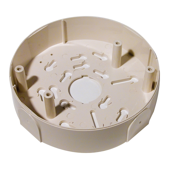
Figure 1:
ALIGNMENT RIBS
Figure 2:
ALIGNMENT RIB
1
A Division of Pittway
1-800-SENSOR2, FAX: 630-377-6495
A78-1826-00
CUT OFF
RIBS (4)
A78-1902-00
A78-1918-00
I56-444-03
Advertisement

Subscribe to Our Youtube Channel
Related Manuals for System Sensor SMB600


Summary of Contents for System Sensor SMB600
- Page 1 SMB600. 2. Pull the wires through the 1.3"/33mm dia. hole in the bottom of the base. The SMB600 must be mounted to a A78-1826-00 UL listed junction box (see Figure 3).
- Page 2 6. Mount the base, using the supplied screws, in the 2. Drill out the appropriate holes using the drill centers SMB600 Surface Mounting Adaptor Kit. provided on the sides of the adaptor (see Figure 4). Do not use conduit larger than 1/2" to connect to the NOTE: When using the B402, B404, or B406 with the sur- SMB600.
Need help?
Do you have a question about the SMB600 and is the answer not in the manual?
Questions and answers