
Related Manuals for Toshiba BMS-IFMB1280U-E


Summary of Contents for Toshiba BMS-IFMB1280U-E
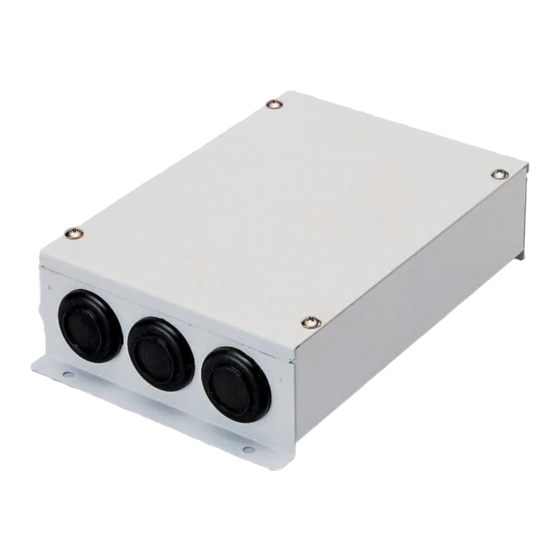
- Page 1 Installation Manual Modbus interface For commercial use Modbus interface Model name: BMS-IFMB1280U-E...
-
Page 2: Table Of Contents
Modbus interface Installation Manual • Thank you very much for purchasing this TOSHIBA Modbus interface. • Please read this manual carefully beforehand for proper installation of the Modbus interface. Contents 1 Precautions for safety ..........2 2 Introduction . -
Page 3: Precautions For Safety
Modbus interface Installation Manual Precautions for safety • Read these “Precautions for Safety” carefully before installation. • The precautions described below include important items regarding safety. Observe them without fail. Understand the following details (indications and symbols) before reading the body text, and follow the instructions. -
Page 4: Introduction
Modbus interface Installation Manual Introduction Applications / Functions / Specifications Applications • The Modbus interface is used to connect air conditioners “with TU2C-LINK Uh Line (hereinafter, referred to as Uh Line) installed” and TCB-IFCG1TLE to Modbus* system. Functions • The Modbus interface converts signals between Uh Line and Modbus Master. Specifications Power supply 220 - 240 VAC, 50/60 Hz... -
Page 5: Before Installation
Modbus interface Installation Manual Before installation Check the following package contents. Item Quantity Remarks Modbus interface Installation Manual Screw M4 x 12 mm tapping screws Cable clamp Use the following wiring materials to connect the communication cables and power cables. (locally procured) Line Description Type... -
Page 6: Connection Of Power Cables / Earth Wires / Communication Cables
Modbus interface Installation Manual Connection of power cables / earth wires / communication cables CAUTION • The RS-485 communication cables have polarity. Connect A(+) to A(+), and B(-) to B(-). If connected with incorrect polarity, the unit will not work. •... - Page 7 Modbus interface Installation Manual The shielded wire of the Uh The shielded wire of the RS-485 To connect 2 cables, Line communication cable communication cable must be earthed on change the preset cable must be earthed on the air address 1 (Modbus interface address SW=1) clamp to the provided one conditioner.
- Page 8 Modbus interface Installation Manual Do not connect the shielded wire of Uh Line communication cable to the earth. Set the RS-485 terminator resistor on the LINK(Uh) U3 and Modbus-Master address1 unit (Modbus interface address U4 have no polarity. SW1=1) and host system. Do not set it here. (Locally procured) Uh Line terminator resistor is set on the air conditioner side.
-
Page 9: Setting
Modbus interface Installation Manual Setting The following settings are necessary to use Modbus interface. • SW1 Sets the Modbus slave addresses of the Modbus interface. A single Modbus interface uses three Modbus slave addresses. (One address for the current interface and two addresses for potential interfaces.) When two or more Modbus interfaces are used for a single line RS-485 bus, set the addresses as indicated in the table below. - Page 10 Modbus interface Installation Manual LED4 LED2 SW1 Modbus interface address set switch LED5 LED3 LED1 Modbus interface address Not used SW2 Test switch (0 usually) Bit1: Uh Line communication setting mode switch. 1 2 3 4 OFF: Normal circumstance; ON: Central controller ID setting mode Bit2: Switches the LED5 display for test runs.
- Page 11 Modbus interface Installation Manual Central controller ID setting mode The central controller ID setting mode changes the central controller ID of the Modbus interface. (central controller ID at the time of factory shipping is central controller ID 20.) The central controller ID number indicates the Uh Line address and communication priority for the Uh Line compatible central control device.
- Page 12 Modbus interface Installation Manual (3) Change of central controller ID • Change SW1 to 1-F and press SW4. • If using Modbus interface with a central control device not compatible with Uh Line, set as “old controller.” Central controller ID Central controller ID7 Central controller ID8 Central controller ID9...
-
Page 13: Test Run Check
Modbus interface Installation Manual Test run check Before starting test run • Set the indoor unit central control address so that it does not match any other indoor unit addresses. • Be sure to press the reset switch SW7 on the Modbus interface when the indoor unit central control address setting has been changed or added. - Page 14 Modbus interface Installation Manual Indoor unit Indoor unit Indoor unit Indoor unit central control SW2 SW1 central control SW2 SW1 central control SW2 SW1 central control SW2 SW1 address address address address (2) Perform the communication status checking between Modbus interface and Modbus Master. Check that the communication with Modbus Master is normally performed.
- Page 15 Modbus interface Installation Manual Manufacturer / Importer 14-EN...
- Page 16 DEC0309101...
Need help?
Do you have a question about the BMS-IFMB1280U-E and is the answer not in the manual?
Questions and answers