Table of Contents
Advertisement
Quick Links
ITA/ENG
rev.5 09/10/2020
EVO 1 AVM
SA700.xx / SA701.xx
MANUALE DI INSTRUZIONE E INSTALLAZIONE
INSTRUCTION AND INSTALLATION MANUAL
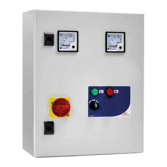
Quadro elettromeccanico avviamento diretto 1 motore con voltmetro, amperometro e
cassetta in metallo.
Direct starting electromechanical control panel 1 motor with voltmeter, ammeter and
metal box .
CUSTOMER SERVICE
customer.service@salupoquadri.com
( )
+39 0 941.1820216
Advertisement
Table of Contents

Subscribe to Our Youtube Channel
Related Manuals for SALUPO EVO 1 AVM


Summary of Contents for SALUPO EVO 1 AVM
- Page 1 ITA/ENG rev.5 09/10/2020 EVO 1 AVM SA700.xx / SA701.xx MANUALE DI INSTRUZIONE E INSTALLAZIONE INSTRUCTION AND INSTALLATION MANUAL Quadro elettromeccanico avviamento diretto 1 motore con voltmetro, amperometro e cassetta in metallo. Direct starting electromechanical control panel 1 motor with voltmeter, ammeter and metal box .
-
Page 2: Table Of Contents
INDICE 1. Istruzioni generali per l’installazione 2. Avvertenze 3. Schemi di collegamento 3.1 Schema di collegamento SA700.xx 3.2 Schema di collegamento SA701.xx 4. Schemi elettrici 4.1 Schema elettrico SA700.xx 4.2 Schema elettrico SA701.xx 5. Impiego 6. Funzionamento generale del quadro 7. -
Page 3: Istruzioni Generali Per L'installazione
1. ISTRUZIONI GENERALI PER L’INSTALLAZIONE ITALIANO Assicurarsi che la linea sia protetta, secondo le normative, in funzione dell'applicazione. Accertarsi che la potenza e la corrente di targa del motore rispecchino i limiti di impiego del quadro. Installare il quadro in ambienti adatti al suo grado di protezione IP65. Per il fissaggio dell'involucro, utilizzare le staffe per i box 03-04 e le apposite predisposizioni per i restanti box. -
Page 4: Schemi Di Collegamento
3. SCHEMI DI COLLEGAMENTO 3.1 Schema di collegamento SA700.xx LINEA DI ALIMENTAZIONE 230Vac 50/60Hz LIVELLO LIVELLO MASSIMO MOTORE MINIMO COLLEGAMENTO CON UN COMANDO ESTERNO GALLEGGIANTE O PRESSOSTATO Max 10 mm² Max 10 mm² Max 6 mm² (M4) 1,4Nm 0,8Nm 0,5Nm 10 mm 10 mm 10 mm... -
Page 5: Schema Di Collegamento Sa701
3. SCHEMI DI COLLEGAMENTO ITALIANO 3.2 Schema di collegamento SA701.xx LINEA DI ALIMENTAZIONE 400Vac 50/60Hz MOTORE LIVELLO LIVELLO MINIMO MASSIMO COLLEGAMENTO CON UN COMANDO ESTERNO GALLEGGIANTE O PRESSOSTATO Max 10 mm² Max 10 mm² Max 6 mm² (M4) 1,4Nm 0,8Nm 0,5Nm 10 mm 10 mm... -
Page 6: Schemi Elettrici
4. SCHEMA ELETTRICO 4.1 Schema elettrico SA700.xx... -
Page 7: Schema Elettrico Sa701
4. SCHEMA ELETTRICO ITALIANO 4.2 Schema elettrico SA701.xx... -
Page 8: Impiego
Può essere utilizzato per qualsiasi tipo di applicazione che necessita un avviamento diretto. 6. FUNZIONAMENTO GENERALE DEL QUADRO E’ possibile far funzionare l’EVO 1 AVM secondo due modalità: - Automatica In questa condizione il quadro avvia il motore solo se il pressostato o interruttore a galleggiante si trova su ON. - Page 9 INDEX 1. Instrucciones generales para la instalación 2. Advertencias Esquemas de enlace Esquema de enlace SA700.xx Esquema de enlace SA701.xx 4. Esquemas eléctrico 4.1 Esquema eléctrico SA700.xx 4.2 Esquema eléctrico SA701.xx 5. Aplicación 6. Funcionamiento general del cuadro 7. Eliminación de aparatos eléctricos y electrónicos viejos 8.
- Page 10 1. GENERAL INSTRUCTIONS FOR INSTALLING Make sure power supply is protected up to standard depending on application. The power of the motor has to be within the control panel's limits of use. Install the control panel in an environment appropriate to its IP65 degree of protection. To fix the enclosure, use the brackets for the boxes 03-04 and the special predispositions for the remaining boxes.
- Page 11 3. WIRING DIAGRAMS ENGLISH 3.1 Wiring diagram SA700.xx POWER SUPPLY 230Vac 50/60Hz MAXIMUM MINIMUM LEVEL MOTORE LEVEL CONNECTION WITH EXTERNAL CONTROL PRESSURE SWITCH OR FLOAT SWITCH Max 10 mm² Max 10 mm² Max 6 mm² (M4) 1,4Nm 0,8Nm 0,5Nm 10 mm 10 mm 10 mm...
- Page 12 3. WIRING DIAGRAMS 3.2 Wiring diagram SA701.xx POWER SUPPLY 400Vac 50/60Hz MOTOR MINIMUM MAXIMUM LEVEL LEVEL CONNECTION WITH EXTERNAL CONTROL PRESSURE SWITCH OR FLOAT SWITCH Max 10 mm² Max 10 mm² Max 6 mm² (M4) 1,4Nm 0,8Nm 0,5Nm 10 mm 10 mm 10 mm...
- Page 13 4. ELECTRICAL DIAGRAM ENGLISH 4.1 Electrical diagram SA700.xx...
- Page 14 4. ELECTRICAL DIAGRAM 4.2 Electrical diagram SA701.xx...
- Page 15 It can be used for any type of application that requires a direct starting. 6. GENERAL OPERATION OF THE CONTROL PANEL It is possible to operate the EVO 1 AVM in two ways: - Automatic In this condition the control panel starts the motor only if the pressure switch or float switch is ON.
-
Page 16: Smaltimento Di Vecchi Apparecchi Elettrici Ed Elettronici
98070 Torrenova (ME) Dichiara che: gli avviatori diretti EVO 1 AVM Monofase e Trifase sono conformi ai requisiti di protezione in materia di sicurezza (bassa tensione) e di compatibilità elettromagnetica specifici previsti dalle Direttive della Comunità Europea 2006/95/CEE del 16 Gennaio 2007, 2004/108/CE del 10 Novembre 2007, 93/68/CEE del 22 Luglio 1993. - Page 17 NOTE ________________________________________________ ________________________________________________ ________________________________________________ ________________________________________________ ________________________________________________ ________________________________________________ ________________________________________________ ________________________________________________ ________________________________________________ ________________________________________________ ________________________________________________ ________________________________________________ ________________________________________________ ________________________________________________ ________________________________________________ ________________________________________________ ________________________________________________ ________________________________________________...
- Page 18 NOTE ________________________________________________ ________________________________________________ ________________________________________________ ________________________________________________ ________________________________________________ ________________________________________________ ________________________________________________ ________________________________________________ ________________________________________________ ________________________________________________ ________________________________________________ ________________________________________________ ________________________________________________ ________________________________________________ ________________________________________________ ________________________________________________ ________________________________________________ ________________________________________________...
- Page 19 NOTE ________________________________________________ ________________________________________________ ________________________________________________ ________________________________________________ ________________________________________________ ________________________________________________ ________________________________________________ ________________________________________________ ________________________________________________ ________________________________________________ ________________________________________________ ________________________________________________ ________________________________________________ ________________________________________________ ________________________________________________ ________________________________________________ ________________________________________________ ________________________________________________...
- Page 20 C/da Pietra di Roma Via Vicolo VI, n°2 98070 Torrenova (ME) ITALY Tel.:+39 - 0941 - 950216 Fax:+39 - 0941 - 958777 www.salupoquadri.com e-mail: info@salupoquadri.com...
Need help?
Do you have a question about the EVO 1 AVM and is the answer not in the manual?
Questions and answers