Table of Contents
Advertisement
Advertisement
Table of Contents

Related Manuals for Blueprint Subsea Oculus M Series


Summary of Contents for Blueprint Subsea Oculus M Series
- Page 1 Oculus M-Series Sonar User Manual...
-
Page 3: Table Of Contents
Oculus M-Series Sonar User Manual Contents 1. Introduction ................................5 2. ViewPoint Software..............................6 2.1. Viewing Sonar Data ............................6 2.1.1. Sonar Display ....................................... 6 2.1.2. Sonar Information ....................................7 2.1.3. Frequency Mode Control ..................................7 2.1.4. Range Control ...................................... 7 2.1.5. - Page 4 Oculus M-Series Sonar User Manual 6. Limited Warranty Policy ............................28 7. Notices..................................29...
-
Page 5: Introduction
Oculus M-Series Sonar User Manual 1. Introduction Traditionally, sonars were mechanical devices that operated by rotating their transducers (transmitters and receivers) to scan the sector in front of or around them. At each transducer position, a sound pulse would be transmitted into the water, and the echoes collected by the receiver before being plotted onto the display. -
Page 6: Viewpoint Software
Oculus M-Series Sonar User Manual 2. ViewPoint Software ViewPoint is a software application that is used to view, record and playback imagery from the Oculus sonar, in addition to providing tools that help configure environmental and network settings. 2.1. Viewing Sonar Data When ViewPoint starts, the Home screen is shown, but no imagery is available until the application is connected to sonar hardware. -
Page 7: Sonar Information
Oculus M-Series Sonar User Manual 2.1.2. Sonar Information Sonar hardware information is shown at the top left of the display below the ‘Connection’ button – this includes the serial number of the connected sonar, network addresses and firmware version in use. Sonar device settings can be adjusted by clicking the ‘Configure Sonar’... -
Page 8: Display Tools
Oculus M-Series Sonar User Manual 2.2. Display Tools For both the Live Data and Playback displays, a selection of tools are available at the bottom right-hand side: 2.2.1. Measurement Mode Toggles Measurement mode, where the user can use the left mouse button to drag a line between two points and range and bearing information will be shown in the cursor information area at the top right hand side of the display. -
Page 9: Replaying Sonar Data
Oculus M-Series Sonar User Manual 2.4. Replaying Sonar Data ViewPoint can be used to review sonar imagery from a previously recorded Log File. To choose a Log File to play back, click the “Open” button from the top-left of the display: An “Open File”... -
Page 10: Application Settings
Oculus M-Series Sonar User Manual 2.5. Application Settings Settings that control the general behaviour of ViewPoint can be adjusted from the “Settings” window that is accessed by clicking the icon at the right-hand side of the programs title bar: When the Settings window is shown, clicking one of the ‘tab’ heading across the top of the window will change its contents. -
Page 11: Colour Theme
Oculus M-Series Sonar User Manual From the “Environment” tab, select one of the following options to specify how the velocity-of-sound (VOS) is calcualted: Fresh Water – salinity is specified as 0 ppt (parts per thousand), and VOS is continuously calcualted from pressure and water temperature sensor readings. -
Page 12: Ip Address & Subnet Mask
Oculus M-Series Sonar User Manual If no DHCP server is found then Oculus will use a default address starting with 169.254.x.x, where the last two number groups (‘x.x’) are the hardware serial number of the Oculus interpreted as two 8-bit numbers (rather than a larger 16-bit number). -
Page 13: Using The Sonar
Oculus M-Series Sonar User Manual 3. Using the Sonar The following sections aim to explain the basics for operation of the Oculus Sonar and how to start interpreting the images it produces. 3.1. Operating Principles Oculus is an active SONAR (SOund Navigation And Ranging), and operates by transmitting pulses of sound into ... - Page 14 Oculus M-Series Sonar User Manual By combining the known Velocity-Of-Sound (VOS – ‘c’) in water with the time the echoes were received (‘t’), the sonar can calculate the distance the sound has travelled (‘d’). As sound must travel from the Sonar to the target object and then back again, the range (‘r’) between the Sonar and target is half of the total distance travelled.
-
Page 15: Acoustic Beam Patterns
Oculus M-Series Sonar User Manual 3.2. Acoustic Beam Patterns When considering how sonars operate, it may help to think of the sonar like a torch being used in a darkened room. Only the parts of the room illuminated by the torch can be seen by the user, and if the torch has a narrow beam then their field of vision is reduced. -
Page 16: Target Visibility
Oculus M-Series Sonar User Manual 3.3. Target Visibility Objects (or targets) that lie within the sonar’s beam will be acoustically “illuminated” and can have their echoes received (target ), while objects that lie outside this (targets ) may not appear on the sonar display: It should be noted that although the above diagrams show a boundary to the sonar beam, but this actually represents the ‘half-power’... -
Page 17: Viewing The Seabed
Oculus M-Series Sonar User Manual 3.4. Viewing the Seabed As discussed in previous sections, the sonar can be thought of like a hand-held torch with an illuminating beam that is wide horizontally and narrow vertically – continuing this analogy, the sonar images shown on the operators display can then be thought of as a “top-down”... -
Page 18: Acoustic Shadows
Oculus M-Series Sonar User Manual 3.5. Acoustic Shadows The similarities between a sonar and torch continue as the ‘illumination’ from the sonar can be used to generate acoustic shadows, and these can be of great assistance to the operator in determining the height, shape and orientation of targets in front of the sonar. - Page 19 Oculus M-Series Sonar User Manual Depending on how close the sonar is to a target can also make a significant difference to the image. Due to the way sounds waves spread out from the transmitter, shadows cast by targets that are far away will be ...
-
Page 20: Understanding Echoes
Oculus M-Series Sonar User Manual 3.6. Understanding Echoes Although it has been mentioned that the sonar display can be thought of as a top-down image of the area in front of them, there are some limitations to this analogy. As the image is illuminated from the side by the sonar, only the edges or faces of targets closest to the sonar will be illuminated. -
Page 21: Range Vs Frequency And Image Quality
Oculus M-Series Sonar User Manual 3.7. Range vs Frequency and Image Quality As previously mentions, some Oculus sonars have two operating modes: Low Frequency, which allows for long range operation with a wide viewing angle – this is useful for searching and surveying tasks. -
Page 22: Summary Of Sonar Operation
Oculus M-Series Sonar User Manual 3.8. Summary of Sonar Operation In general, the following points summarise operation of the sonar: The sonar image shows “top-down” type display of the echoes received from the targets leading edges. Only targets illuminated by the sonar beam can be seen: 130°/80°... -
Page 23: Technical Reference
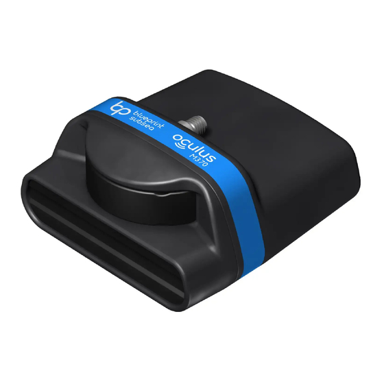
Oculus M-Series Sonar User Manual 4. Technical Reference 4.1. Specifications Mechanical Dimensions 125mm long 122mm wide 62mm high Construction Anodised Aluminium (Titanium available on request ) Weight 980g (air) 360g (water) Neutral buoyancy pack available Depth Rating 300m Temperature Range -5°C to +35°C (operating) -20°C to +50°C (storage) -
Page 24: Mechanical Dimensions
Oculus M-Series Sonar User Manual 4.2. Mechanical Dimensions A 3D STEP model of the sonar housing is available on request via the website or Technical Support contact details at the end of this manual. -
Page 25: Sonar Connector Pinout
Oculus M-Series Sonar User Manual 4.3. Sonar Connector Pinout IE55-12 series Bulkhead Connector (face view) Signal Comments GROUND Power supply Ground POWER IN+ Power supply Positive (see specifications for voltage range) ETHERNET TX- 100BaseT TX Pair Minus (transmit from the Sonar) ETHERNET TX+ ... -
Page 26: Ethernet Deck Lead Wiring
Oculus M-Series Sonar User Manual 4.5. Ethernet Deck Lead Wiring Drawing… Diagram for illustrative purposes only and not to scale – see wiring description below for connections. Front Face Materials… Item Description Part Number Impulse IE55-12 series inline moulded female plug. IE55-12-CCP/UT Souriau UTS series 6-way free male plug, shroud and Pin Housing: UTS6JC106P... -
Page 27: Product Support
To protect our staff, please ensure the product has been suitably decontaminated and cleaned prior to return such that it is safe to handle. Please return the product back to Blueprint Subsea, using an insured courier and delivery confirmation. - Page 28 Oculus M-Series Sonar User Manual 6. Limited Warranty Policy The manufacturer, Blueprint Design Engineering Limited (hereafter after referred to as Blueprint), warrants that at the time of shipment all products shall be free from defects in material and workmanship and suitable for the purpose specified in the product literature.
- Page 29 7. Notices Copyright Blueprint Subsea is a trading name of Blueprint Design Engineering Ltd. Copyright © 2017 Blueprint Design Engineering Limited, all rights reserved. No part of this publication may be reproduced, stored in a retrieval system, or transmitted in any form or by means (electronic, mechanical, photocopying, recording or otherwise), without the prior written permission of Blueprint Design Engineering Ltd.
- Page 30 Oculus M-Series Sonar User Manual Restriction of Hazardous Substances Statement Under the European Union (EU) directive on the 'Restriction of Hazardous Substances' (Directive 2002/95/EC), from July 1, 2006, electrical and electronic equipment cannot contain lead ("lead free"), mercury, cadmium, hexavalent chromium, polybrominated biphenyls (PBB) or polybrominated diphenyl ethers (PBDE). All components of the ArtemisPRO system, sold by Blueprint Design Engineering Ltd, fully comply with this legislation where applicable.
- Page 32 Distributor… P/N: BP01222.1 UM-148-P01222-01 March 2017...
Need help?
Do you have a question about the Oculus M Series and is the answer not in the manual?
Questions and answers