Table of Contents
Advertisement
Quick Links
Advertisement
Table of Contents

Related Manuals for Blueprint Subsea Starfish 453OEM


Summary of Contents for Blueprint Subsea Starfish 453OEM
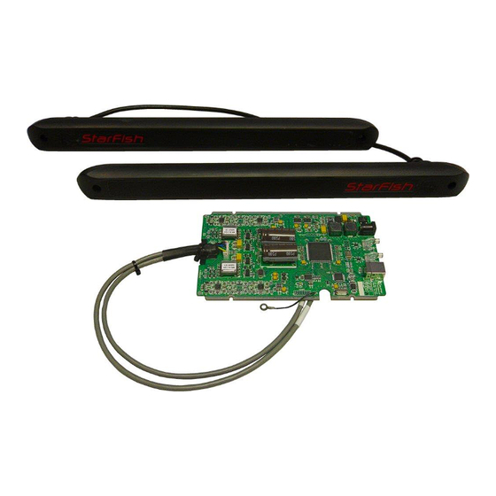
- Page 1 StarFish Sidescan Sonar 453OEM System Manual...
-
Page 3: Table Of Contents
StarFish 453OEM System Manual Contents 1. Introduction ................................4 2. Installation ................................5 2.1. Choosing A Mounting Location ......................... 5 2.2. Transducer Mounting & Sealing ........................6 2.3. Circuit Board Mounting ............................. 7 2.4. Power Supply Connection ..........................8 2.5. USB Data Connection ............................8 2.6. -
Page 4: Introduction
StarFish 453OEM System Manual 1. Introduction Thank you for purchasing the StarFish453OEM Seabed Imaging System, a revolutionary high definition side-scan sonar system capable of producing near photographic quality sonar images of the seabed. Whether surveying lakes, rivers or the open ocean for dive sites, submerged structures, shipwrecks or research purposes, StarFish gives you the capability to capture detailed images of the seabed for work or play, making hi- tech seabed imaging accessible to anyone. -
Page 5: Installation
StarFish 453OEM System Manual 2. Installation 2.1. Choosing A Mounting Location Before you can start using the Starfish453OEM Sonar system in the field, you will need to mount the sonar transducers to your underwater platform. Correct mounting of the sonar is essential in order to achieve the best image results, and as each setup is different you should consider the following points when deciding on a suitable mounting location…... -
Page 6: Transducer Mounting & Sealing
StarFish 453OEM System Manual 2.2. Transducer Mounting & Sealing The StarFish transducers should be mounted onto the hull of the vehicle (or subsea platform) using 2 M4 fixings, with centres 381mm apart as shown in the diagram below. For best acoustic performance, the transducers should be mounted such that they are angled 30° down from the... -
Page 7: Circuit Board Mounting
StarFish 453OEM System Manual 2.3. Circuit Board Mounting The StarFish electronics can be mounted onto a base plate using 4 M3 fixings that locate into the notches on the edge of the board (circled in blue below). The should be stood off a base plate using spacers with a minimum height of 3mm. -
Page 8: Power Supply Connection
StarFish 453OEM System Manual For best electrical performance, the electronic should be placed into an enclosed metal housing that is electrically connected to the same Ground reference as the power supply input – this will reduce electrical noise and interference that may appear on the sonar display. -
Page 9: Transducer Connections
StarFish 453OEM System Manual 2.6. Transducer Connections The StarFish electronic circuit board is pre-fitted with the transducer cable loom connected to “J1”. Once the transducers have been mounted and sealed into the housing, they should be connected as shown in the diagram below to the electronics module: The grey cables from the circuit board are labelled with “Port”... -
Page 10: Using The Sonar
StarFish 453OEM System Manual 3. Using The Sonar 3.1. Operation Once the StarFish453 transducers and electronics module have been installed onto your platform, the system is ready for use. If this is the first time you’re using the StarFish system, it is recommended you install the “Scanline” software and USB hardware drivers on your embedded PC before connecting the electronics module to it. -
Page 11: Understanding Sidescan Imagery
StarFish 453OEM System Manual 4. Understanding Sidescan Imagery Interpreting side-scan imagery may seem difficult at first, but with practice and some knowledge of how the sonar works, it doesn’t take very long for an operator to understand what the seafloor is doing below the sonar, and if there are any targets on it. -
Page 12: What Does A Side-Scan Sonar Image Look Like
StarFish 453OEM System Manual 4.2. What Does A Side-Scan Sonar Image Look Like? The figure below is a real image captured by a StarFish sonar, where each horizontal line is a representation of time versus the intensity of the reflected echoes. The further something is away from the centre line of the display, means the longer it took for the echo to be received. -
Page 13: Calculating The Distance To A Target
StarFish 453OEM System Manual 4.4. Calculating The Distance To A Target As mentioned earlier, the sonar display shows the recorded echoes over a period of time, and we have seen how we can work out the depth below the sonar from this. -
Page 14: Reflected Target Intensity
StarFish 453OEM System Manual 4.6. Reflected Target Intensity To complete our understanding of the basics of sonar imagery, we need to consider the brightness information (intensity of echo) shown on the sonar display. As with a surface reflecting light, different surface textures and materials of targets have different acoustic reflective properties. -
Page 15: Example Side-Scan Sonar Images
StarFish 453OEM System Manual 4.7. Example Side-Scan Sonar Images Lake Bed Scan showing boat moorings at the bottom (concrete blocks in craters of silt). The dark area on the left channel is the shoreline. A boat with wake is visible on the right. -
Page 16: Gain & Contrast Settings
StarFish 453OEM System Manual 4.8. Gain & Contrast Settings When operating your sonar, the adjustments you will make to the gain and contrast controls are critical in achieving good side-scan imagery. This section examines the function and purpose of these controls…... -
Page 17: Tips For Good Imagery
StarFish 453OEM System Manual 4.10. Tips For Good Imagery Vessel Speed When operating the StarFish, remember that it is “pinging” at a fixed rate (depending on range). The faster you move the sonar transducers over the seabed, the more compressed images will appear on the display. -
Page 18: Safety
StarFish 453OEM System Manual 6. Safety 6.1. Electrical Safety • The AC power adaptor and electronics modules are NOT protected against the ingress of water, so take care to avoid exposing the unit to sources of conductive liquids. Dry wet hands before handling the AC power adaptor or surface control box. -
Page 19: Care Of Your Starfish
StarFish 453OEM System Manual 7. Care Of Your Starfish 7.1. Operational Care In addition to the points highlighted in the “Safety” section, please observe the additional precautions… • Do not operate the product near a source of heat that may cause the operational temperature parameters to be, or stack other heat generating equipment on top of the unit. -
Page 20: Troubleshooting
StarFish 453OEM System Manual 8. Troubleshooting Below is a table of common problems and solutions, but if you have a problem that cannot be solved from the table below, or an issue that is not covered, please contact StarFish technical support. -
Page 21: Product Support
• If your product is still under warranty, please include a copy of your receipt (showing proof and date of purchase). • Please return the product back to Blueprint Subsea, using an insured courier and delivery confirmation. -
Page 22: Limited Warranty Policy
StarFish 453OEM System Manual 10. Limited Warranty Policy The manufacturer, Blueprint Design Engineering Limited (hereafter after referred to as Blueprint), warrants that at the time of shipment all products shall be free from defects in material and workmanship and suitable for the purpose specified in the product literature. -
Page 23: Notices
11. Notices Copyright Blueprint Subsea is a trading name of Blueprint Design Engineering Ltd. Copyright © 2017 Blueprint Design Engineering Limited, all rights reserved. No part of this publication may be reproduced, stored in a retrieval system, or transmitted in any form or by means (electronic, mechanical, photocopying, recording or otherwise), without the prior written permission of Blueprint Design Engineering Ltd. -
Page 24: Specifications
StarFish 453OEM System Manual 12. Specifications 12.1. Mechanical Drawings... -
Page 25: Technical
StarFish 453OEM System Manual 12.2. Technical Transducer Frequency 450kHz CHIRP Operating Range 100m per channel Horizontal Beam Width 0.5° (@ -3dB signal level) Vertical Beam Width 60° (@ -3dB signal level) Transducer Mounting Angle Tilted Down 30° from Horizontal recommended... -
Page 26: Acoustic Beam Patterns
StarFish 453OEM System Manual 12.3. Acoustic Beam Patterns The StarFish453OEM uses a 430kHz to 470kHz, 400µs swept frequency transmission (CHIRP). • Blue trace represents single 450kHz centre frequency • Red trace represents average swept 430kHz to 470kHz frequency chirp (BW 40kHz, Q 11.25) •... - Page 28 Distributor… P/N: BP01006-3 UM-143-P01006-03 December 2017...
Need help?
Do you have a question about the Starfish 453OEM and is the answer not in the manual?
Questions and answers