Table of Contents
Advertisement
Quick Links
•
wdwd
©2009
burster
präzisionsmesstechnik gmbh & co kg
All rights reserved
Valid from:
2009-02-27
Torque sensor
Model 8625
Manufacturer:
burster präzisionsmesstechnik gmbh & co kg
Talstrasse 1 – 5
76593 Gernsbach,
Germany
Tel.:
(+49) 07224 / 6450
Fax:
(+49) 07224 / 64588
E-mail:
info@burster.de
www.burster.de
Postfach 1432
76587 Gernsbach,
Germany
380-008625EN-5170-021511
Advertisement
Table of Contents

Related Manuals for Burster Burster


Summary of Contents for Burster Burster
- Page 1 • wdwd Torque sensor Model 8625 ©2009 burster Manufacturer: präzisionsmesstechnik gmbh & co kg burster präzisionsmesstechnik gmbh & co kg All rights reserved Talstrasse 1 – 5 Postfach 1432 76593 Gernsbach, 76587 Gernsbach, Germany Germany Valid from: 2009-02-27 Tel.: (+49) 07224 / 6450...
- Page 2 Furthermore, burster assumes no liability for direct, indirect or incidental damages as well as consequential or other damages arising from the provision and use of the present documentation.
- Page 3 Torque sensor Model 8625 Page 3...
- Page 4 Model 8625 Torque sensor Page 4...
- Page 5 Torque sensor Model 8625 Warning! The following instructions must be observed to prevent injuries: Observe all safety notices, instructions and regulations Safety equipment must be in working order during operation The sensor must only be used if it is undamaged Caution! The following points must be observed to prevent injuries and damage to property:...
- Page 6 Model 8625 Torque sensor Page 6...
-
Page 7: Table Of Contents
Torque sensor Model 8625 Contents Introduction ........................9 Intended use......................9 Personnel ....................... 9 Conversions and modifications................9 Terms ........................9 Preparations for use ......................11 Transport and unpacking ..................11 Storage ......................... 11 Principle of operation ...................... 13 Mechanical structure..................... 13 Electrical design .................... - Page 8 Model 8625 Torque sensor Torque direction ....................29 Static / Quasi-static torques...................29 Dynamic torques ....................30 6.4.1 Estimating the mechanical natural frequency ..........30 Interference ......................31 Option: Check function ..................31 Maintenance ........................33 Maintenance schedule ..................33 Troubleshooting table ....................34 Taking out of use ......................35 Disposal ..........................35 Page 8...
-
Page 9: Introduction
Torque sensor Model 8625 1. Introduction 1.1 Intended use Torque sensors are designed to measure torques. This measured quantity is suitable for open-loop and closed-loop control functions. The torque sensor 8625 is no safety component. Transport and store the sensors correctly. The device must be fitted, commissioned, operated and removed properly. - Page 10 Model 8625 Torque sensor Unfixed end The "unfixed end" refers to the shaft of the arrangement (drive, load). You must be able to move this shaft with a torque that is far lower than the rated torque of the sensor. i.e.
-
Page 11: Preparations For Use
Torque sensor Model 8625 2. Preparations for use 2.1 Transport and unpacking Only transport the model 8625 sensors in their original packaging or in packaging of equivalent quality. The sensor must not be able to move within the packaging. Protect the sensor from damp. Inspect the sensor carefully for damage when removing from the packaging. - Page 12 Model 8625 Torque sensor Page 12...
-
Page 13: Principle Of Operation
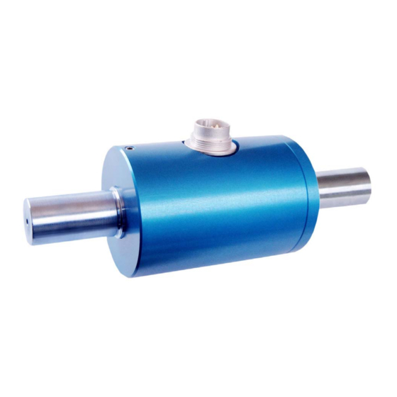
Torque sensor Model 8625 3. Principle of operation 3.1 Mechanical structure The sensor does not contain any rotating parts. It comprises a torsion bar having shaft ends. The strain gauges are mounted on this torsion bar. This arrangement is protected by a case that also carries the electrical connector or cable connection. Cabel Kabel Case... - Page 14 Model 8625 Torque sensor Page 14...
-
Page 15: Installation
Torque sensor Model 8625 4. Installation 4.1 Mechanical installation Caution! Damage from excessive torques, bending moments or axial forces. Support the sensor while it is being fitted. Avoid dropping the sensor. Make electrical connections to sensor during fitting. Check the measurement signal. -
Page 16: Couplings
Model 8625 Torque sensor 4.1.2 Couplings For the 8625 series torque sensors use couplings that can correct an axial, radial and angular misalignment of the shafts. These couplings must protect the sensor from large forces. Alignment options using half couplings Figure 5: Half coupling Figure 6: angular misalignment Figure 7: axial misalignment... - Page 17 Torque sensor Model 8625 Alignment options using full couplings Figure 10: Full coupling You can use full couplings to correct angular, axial and radial misalignments of the shafts. Figure 11: angular misalignment Figure 12: axial misalignment Figure 13: radial misalignment Page 17...
-
Page 18: Shaft Connection: General Information
Model 8625 Torque sensor 4.1.3 Shaft connection: general information Before installation, clean the shafts using a solvent such as acetone. There must be no foreign matter on the shafts when fitted. Provide a collar with the correct fit for the connection. If you are using clamping elements for connecting the shafts: Only use clamping elements that provide reliable transmission of the torques that arise. - Page 19 Torque sensor Model 8625 Maximum forces The maximum forces for the sensor are shown below for a lever of length "r": Figure 14: F applied at a distance "r" from the shaft axis Sensor rated torque r = 5 mm r = 10 mm r = 20 mm 0.005 Nm...
-
Page 20: Shaft Connection: Sensors With 0.05 Nm To 10 Nm Ranges
Model 8625 Torque sensor 4.1.5 Shaft connection: sensors with 0.05 Nm to 10 Nm ranges Note: The sensors are very sensitive to overload. Handle these sensors with the necessary care. Connect up the sensor electrically. Check the signal output from the sensor throughout fitting. This signal must always remain within the permitted range. - Page 21 Torque sensor Model 8625 sensor bearing coupling coupling fixed Kupplung Sensor Kupplung Lager fest bzw. Figure 16: Mounting example: uncovered sensor between two half couplings bearing coupling sensor Sensor fixed Lager Kupplung fest bzw. Figure 17: Mounting example: uncovered sensor with full coupling Maximum forces The maximum forces for the sensor are shown below for a lever of length "r": Figure 18: F...
-
Page 22: Shaft Connection: Sensors With Ranges Greater Than 20 Nm
Model 8625 Torque sensor 4.1.6 Shaft connection: sensors with ranges greater than 20 Nm If you are connecting the shafts using a clamping device Use a suitable clamping device Observe the specification given by the manufacturer of the clamping device. In general: The shafts must have an appropriate fit for the connection. - Page 23 Torque sensor Model 8625 sensor bearing coupling coupling fixed Kupplung Sensor Kupplung Lager fest bzw. Figure 19: Mounting example: uncovered sensor between two half couplings bearing coupling sensor Sensor fixed Lager Kupplung fest bzw. Figure 20: Mounting example: uncovered sensor with full coupling Page 23...
-
Page 24: Electrical Connection
Model 8625 Torque sensor 4.2 Electrical connection 4.2.1 Pin-out of the electrical socket 6-pin connector 6-pin electrical Function socket Sensor excitation (-) Sensor excitation (+) Shield Sensor signal (+) Sensor signal (-) Figure 21: view from the solder side Check (option) 7-pin connector 7-pin electrical Function... -
Page 25: Cable
Torque sensor Model 8625 4.2.2 Cable Always use shielded cable with as low a capacitance as possible. burster can supply cables that have been tested with our sensors and satisfy instrumentation requirements. Relationship between sensitivity and cable length Note: With extension cables, the sensor sensitivity is affected by the cable length as a function of the bridge resistance and the conductor cross-section. -
Page 26: Positioning The Measurement Cable
Model 8625 Torque sensor 4.2.4 Positioning the measurement cable Place the cable far enough away from high-power equipment. These include transformers, motors, contactors, frequency converters and so forth. Otherwise the electromagnetic fields from such equipment will act with their full effect on the measuring chain, causing incorrect measurements. -
Page 27: Calibration
Torque sensor Model 8625 5. Calibration The torque sensors from burster präzisionmesstechnik are already traceably adjusted and tested in the factory. As an option we offer manufacturer calibration of the sensor. 5.1 Manufacturer calibration The manufacturer calibration involves checking sensor data against traceably calibrated measuring instruments. - Page 28 Model 8625 Torque sensor Page 28...
-
Page 29: Measurement
Torque sensor Model 8625 6. Measurement 6.1 Switching on Let the sensor warm up for about 5 minutes. 6.2 Torque direction A torque is designated a clockwise torque if the torque acts in a clockwise direction when looking towards the shaft end. In this case you obtain a positive electrical signal at the sensor output. Wellenende Shaft end Figure 23: Torque (looking towards the drive end) -
Page 30: Dynamic Torques
Model 8625 Torque sensor 6.4 Dynamic torques Caution! Operating the setup close to the natural resonance results in permanent damage. The frequency of torques must lie below the natural frequency of the mechanical test setup. Limit the peak-to-peak torque variation to 70 % of the rated torque. The calibration applies to measurements of both static and dynamic torques. -
Page 31: Interference
Torque sensor Model 8625 6.5 Interference Interference is particularly likely to produce measurement errors for small torques. Forms of interference include: • Vibrations • Air movements for small torques • Temperature gradients • Temperature changes • Electrical interference • Magnetic interference •... - Page 32 Model 8625 Torque sensor Function: Excitation + Strain gauge Signal + Signal - External switch Check Excitation - External Internal Applying the positive strain gauge excitation voltage adjusts the measuring bridge electrically so that a measurement signal is output that equals 100 % of the rated value. 50 % and 80 % are also possible as an option.
-
Page 33: Maintenance
Torque sensor Model 8625 7. Maintenance 7.1 Maintenance schedule Action Frequency Date Date Date Check cable and connector 1x annually Calibration < 26 months Check the fitting (flange, shafts) 1x annually Page 33... -
Page 34: Troubleshooting Table
Model 8625 Torque sensor 7.2 Troubleshooting table This table contains the most common faults and corrective actions. Fault Possible cause Remedial action No signal No power excitation Connect excitation Outside permitted range Check excitation No mains excitation Connect excitation Cable faulty Repair cable Signal output not connected Connect output correctly... -
Page 35: Taking Out Of Use
Torque sensor Model 8625 8. Taking out of use Remove the sensors correctly. Protect the sensor from knocks. Protect the sensor from bending moments e.g. from levers. Support the sensor. Avoid dropping the sensor. 9. Disposal Observe the relevant regulations. Page 35...
Need help?
Do you have a question about the Burster and is the answer not in the manual?
Questions and answers