
Related Manuals for Arduino MNC6


Summary of Contents for Arduino MNC6
- Page 1 “MNC6” Arduino Interchangeable Nixie Clock Rev1 & Rev1.2 Construction Manual MNC6ConstructionManualRev1...
-
Page 2: Table Of Contents
Index Table of Contents Index............................2 What this document is about....................3 Contact Information........................ 3 Troubleshooting........................3 Safety............................3 External power supply......................4 Board Versions........................4 Board layout..........................5 Connecting the external components.................6 Construction..........................7 Preparation......................... 7 Input Power......................... 8 Tube holder sockets...................... -
Page 3: What This Document Is About
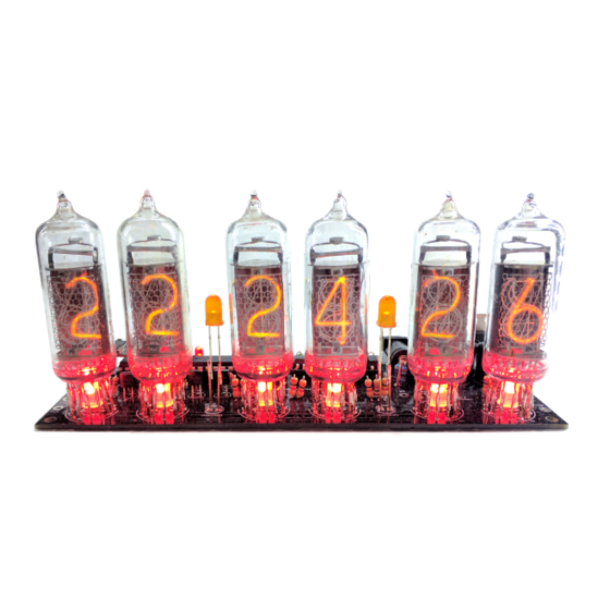
What this document is about This document is the construction manual for the “MNC6” Arduino based Interchangeable Medium Tube Nixie Clock shown on the first page. This is a brand new design, and gives you a great features in an easy to build, high quality Nixie Clock. -
Page 4: External Power Supply
It is not advised to use more than 12V. The absolute maximum permissible is 16V DC. Higher voltages than this will surely damage the clock. Board Versions This manual covers versions MNC6 V1.0 • MNC6 V1.2 • While there might be detail differences in the layout and silk screen of the board, you can follow the same instructions. -
Page 5: Board Layout
Board layout For reference, the board layout is as shown (viewed from the top): The connections are: Connector Description POWER External power can be applied to the board with this connector using the (Barrel Jack) 5.5mm jack. The absolute maximum input voltage is 16V. Any higher voltage than this will damage the board within a few seconds! The input current ranges from 300mA to 500mA depending on the tubes and the number of LEDs patterns you are using. -
Page 6: Connecting The External Components
“Auxiliary output”. The clock is capable of driving additional APA106 elements in addition to the 6 on-board individually addressable tube back lights, as well as an external sounder if you want to use an alarm. Note that the “LED Out2 and “SND” functions require a code change to implement them, the standard software does not support them. -
Page 7: Construction
Construction Preparation You should have a small tipped soldering iron, some thin (<= 1mm, ideally 0.6mm – 0.8mm) solder, and electronic side cutters. There are no special or difficult to solder components needing assembly. You should leave an hour for construction and testing, but usually you will be ready long before the hour is finished. -
Page 8: Input Power
Input Power Parts List: CON1 Barrel Jack The Low Voltage circuit is a buck switched mode voltage regulator. Its job is to reduce the external voltage from the power adapter down to a known and stable 5V to drive the micro- controller and the LEDs. -
Page 9: Tube Holder Sockets
Tube holder sockets Parts List: J8 - J13 2 x 6 2.54mm Female headers We suggest you put the sockets on the board, but you can also reverse the connectors and put the header pins on the board if you prefer. We prefer to put the sockets on the board, because this means that no high voltages are exposed when the tube is unplugged. -
Page 10: Tube Holder Preparation: Tubes
Tube holder preparation: Tubes This step can be skipped if you have bought the tubes already assembled onto tube holders! Instead, go to the section “Backlight LEDs”! Parts List: 6 tubes Mid sized Nixie tubes 6 holders Tube holders to suit This step mounts the tubes on the tube holder boards. - Page 11 Put the leads one at a time into the holes on the board, making sure to leave the holes either side of the anode empty if you have tubes without decimal points. Once all the leads are in, push the tube down so that it is about 5mm away from the board. Check that the tube is upright and not obviously tilted to one side, or backwards or forwards.
- Page 12 Some Common Tube pin outs: IN-14. Pins 2 and 13 are decimal points, and are often removed on the tubes. The other pins are given below. Connection Anode Right decimal point Digit 1 Digit 2 Digit 3 Digit 4 Digit 5 Digit 6 Digit 7 Digit 8...
-
Page 13: Tube Holder Preparation: Header Pins
Tube holder preparation: Header pins This step can be skipped if you have bought the tubes already assembled onto tube holders! Instead, go to the section “Backlight LEDs”! Parts List: J8 - J13 2 x 6 2.54mm Male header pins We suggest you put the sockets on the board, but you can also reverse the connectors and put the header pins on the board if you prefer. -
Page 14: Backlight Leds
Backlight LEDs Parts List: LED1 - 6 APA106 Now that you have your tubes on holders, you can put in the LEDs. The top of the dome on the LED should touch the bottom of the tube, through the hole in the tube holder. This provides support to the tube to stop it tipping backwards. -
Page 15: Separator Neons
Separator neons Parts List: NE1 - 4 4mm neons Put the 4 neons in the spaces on the board. Each pair is in series, and so will not work until both are in place. For best results, mount one higher than the other. Put the tubes in so you can tell how the end result will look. -
Page 16: Front Panel Components
Front Panel components When all the components are installed, you are finished with the board. 6 pin header BTN1 - 2 Momentary push button PIR detector (optional) The LDR should be mounted in such a way that the flat face of the LDR is exposed to the ambient light. -
Page 17: Optional "Wifi
Optional “WiFi” Parts List: ESP1 ESP-01 module 2x4 Female Header Socket The board comes with a high precision, battery backed DS3231 RTC module. If you want to take advantage of the features available with the WiFi module, you can add this at an time if you did not order it with the original module. -
Page 18: Troubleshooting
Troubleshooting If not everything goes as you expect, please refer to the test steps during the construction and the associated troubleshooting tips. If that does not cover the problem you have, please see below. If you still can't find the answer, contact us! The tubes flash (or blink) on and off. -
Page 19: Programming The Micro-Controller
Programming the micro-controller The board comes per-programmed. You don't need to program it, but you might want to. You can update the micro-controller with a newer version of the software, or even create your own software, and load it onto the chip. We have gone to a lot of trouble to make this as easy as possible. - Page 20 Revisions: V0001: 23Jan2021: Initial version V0002: 4Aug2021: Add store links for programmer, add PIR info...
Need help?
Do you have a question about the MNC6 and is the answer not in the manual?
Questions and answers