Table of Contents
Advertisement
Quick Links
Introduction
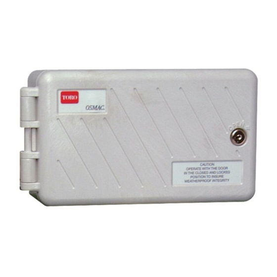
The OSMAC RDR Satellite Controller is designed for installation on a substantial concrete foundation with imbedded
conduit of various diameters to enable power, field and earth ground wiring to be routed into the cabinet for connection.
A mounting bolt positioner and basic mounting hardware components are included with each controller. Additional materials
required to complete the installation must be obtained separately. A material list can be compiled by reading through the
instructions completely prior to starting the installation.
CAUTION: For your protection and the safety of the product user, comply with all Caution and Warning
statements within this document. All installation practices must comply with all applicable national and/or local
electrical and construction codes.
Foundation Construction
1. Prepare a hole for the foundation and
wiring conduit using the minimum
recommended dimensions shown in
Figure 1.
Note: Refer to local electrical codes for
required depth of buried wiring.
2. Trench to the foundation site as
required for each wiring run.
3. Position straight and sweep elbow
conduit sections in foundation hole as
shown. Tape the conduit ends to seal
out dirt. Backfill soil to form a 6"
(15.2cm) foundation depth. Conduit
should not extend more than 2" (51mm)
above the finished top surface of the
foundation.
4. Prepare the sides of the foundation hole
with wood forms.
5. Prepare the mounting bolt positioner
with the 5/16 x 4-1/2" bolts and nuts
(provided) as shown in Figure 1. The
threads should extend 2" (51mm) from
the top surface of the bolt positioner.
6. Pour concrete into the formed
foundation hole. Press the mounting
bolt positioner into the concrete until it is
flush and level with the foundation
surface and aligned with the conduit.
7. Finish the concrete with a level flat area
of 16" x 16" (41cm x 41cm) for the
pedestal base. To prevent pooling at the
base of the pedestal, add a slight taper
away from the cabinet base contact
area. Allow concrete to sufficiently
harden before continuing.
8. Remove the hex nuts from the mounting
studs. Remove the cabinet cover and
doors. Carefully position the controller
onto the studs. Install a flat washer and
a hex nut on each stud and tighten
securely.
®
Toro OSMAC
Electric Actuation Models
Installation Instructions
Figure 1
Wood Form
Plastic Cabinet Base Area
(Conduit Recommendations)
3/4" (19mm) – Power
2" (51mm) – Field
(24 Stations Each)
Mounting Bolt Positioner
3/4" (19mm) – Earth Ground
2" (51mm) Max.
6" (15.2cm)
Mounting Bolt
Positioner
2"
(51mm)
RDR Field Satellite
FRONT
30"
(76cm)
RELEASED Version
©Toro 2006-2006
30"
(76cm)
Taper
See *Note
Advertisement
Table of Contents

Summary of Contents for Toro OSMAC RDR Satellite Controller
- Page 1 Installation Instructions Introduction The OSMAC RDR Satellite Controller is designed for installation on a substantial concrete foundation with imbedded conduit of various diameters to enable power, field and earth ground wiring to be routed into the cabinet for connection. A mounting bolt positioner and basic mounting hardware components are included with each controller. Additional materials required to complete the installation must be obtained separately.
- Page 2 The following instructions depict one of several acceptable earth grounding methods. Due to variables in soil composition and terrain, the method shown may not be suitable for your installation site. Contact your local Toro distributor for assistance and availability of the required earth ground resistance test instrument. Recommended ground testers are: AEMC Instruments, model 3710 clamp-on tester, or Biddle Megger, model 250260 (or equivalent).
- Page 3 CAUTION: If connecting more than one valve per station, do not exceed 0.75A (18 VA) maximum. STA 17 STA 18 STA 19 STA 20 STA 21 STA 22 STA 23 STA 24 Pump Terminal Common Terminals RELEASED Version ©Toro 2006-2006...
- Page 4 Note: The decoder module utilizes a programmable frequency synthesizer which enables each of the preprogrammed frequencies to be changed as needed for the irrigation site conditions. Contact your local Toro distributor for additional information regarding frequency reprogramming. Important: The base station transmitter, hand-held radio and frequency decoder module must be set to the same frequency to enable communication.
- Page 5 3 Amp “Slow Blow” several high voltage surges before malfunction occurs. To ensure proper surge Fuse P/N 363-1222 pill condition, a periodic test schedule should be established and maintained. Contact an authorized Toro distributor for service assistance. RELEASED Version ©Toro 2006-2006...
- Page 6 Turns on individual stations as switches; i.e., does not simultaneously energize the pump. Note: Will not turn off the pump if already running. E.g., 7524 25 35 45 turns on stations 25, 35 and 45 without energizing the pump. RELEASED Version ©Toro 2006-2006...
- Page 7 Maximum Load Per Station Output: 4.0A Circuit Breaker – Control Functions 0.75A (18 VA) Pump/Common & Communication Surge Protection Module: Maximum Load Per Pump/Master Valve Output: 0.5A Fuse 0.75A (18 VA) Maximum Total Load: 3.0A (72 VA) RELEASED Version ©Toro 2006-2006...
- Page 8 International: This is a CISPR 22 Class A product. In a domestic environment, this product may cause radio interference, in which case the user may be required to take adequate measures. © 2002 The Toro Company, Irrigation Division • An ISO-9001-Certified Facility Form Number 373-0203 Rev. B RELEASED Version ©Toro 2006-2006...


Need help?
Do you have a question about the OSMAC RDR Satellite Controller and is the answer not in the manual?
Questions and answers