Table of Contents
Advertisement
Quick Links
Advertisement
Table of Contents

Related Manuals for Topcon GLS-1500 Series


Summary of Contents for Topcon GLS-1500 Series
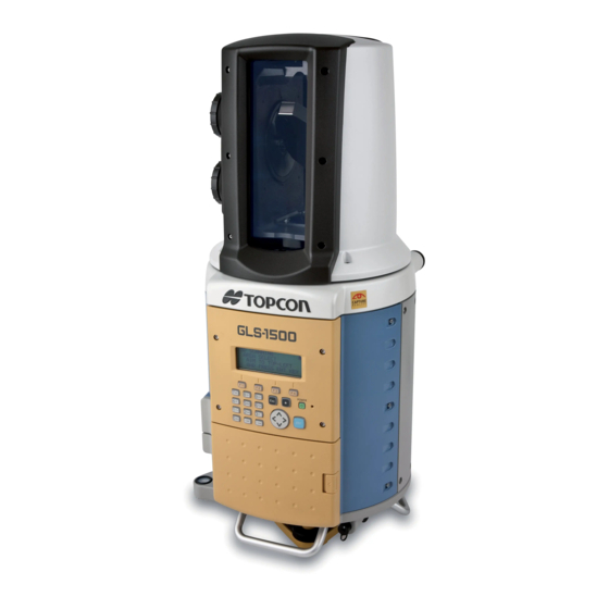
- Page 1 INSTRUCTION MANUAL LASER SCANNER GLS-1500 SERIES 64651 90021...
- Page 3 FOREWORD Thank you for purchasing the TOPCON Laser Scanner, GLS-1500 series. For the best performance of the instruments, please carefully read these instructions and keep them in a convenient location for future reference.
-
Page 4: General Handling Precautions
General Handling Precautions Before starting work or operation, be sure to check that the instrument is functioning correctly with normal performance. Using the instrument on rainy days It may not be possible to use the instrument if there are water drops on the glass of the windows. - Page 5 Removing the instrument When removing the instrument from the case, hold by the handle and handgrip and pick it up while keeping it level. Head Handgrip Storing the instrument When storing the instrument in the case, first install the head cover, hold by the handle and handgrip, and lower into the case while keeping it level.
-
Page 6: Display For Safe Use
• There is a risk of fire, electric shock or physical harm if you attempt to disassemble or repair the instrument yourself. This is only to be carried out by TOPCON or an authorized dealer, only! • High temperature may cause fire. - Page 7 CAUTION • Use of controls or adjustment or performance of procedures other than those specified herein may result in haz- ardous radiation exposure. • Risk of injury by overturn the carrying case. Do not stand or sit on the carrying cases. •...
-
Page 8: User
User 1)This product is for professional use only! The user is required to be a qualified surveyor or have a good knowledge of surveying, in order to understand the user and safety instructions, before operating, inspecting or adjusting. 2)Wear the required protectors (safety shoes, helmet, etc.) when operating. Exceptions from Responsibility 1)The user of this product is expected to follow all operating instructions and make periodic checks of the product’s performance. -
Page 9: Laser Safety
"Complies with FDA performance standards for laser products except for deviations pursuant to Laser Notice No. 50, dated (July 26, 2001)" As per the said standard, the GLS-1500 series is classified as "Class 1 Laser Products". In case of any failure, do not disassemble the instrument. Contact TOPCON or your TOPCON dealer. -
Page 10: Table Of Contents
Contents FOREWORD ..........1 General Handling Precautions. - Page 11 6 PROJECT SETTINGS ........6-1 6.1 Creating a New Project.
-
Page 12: Standard Components
Standard Components The numerical value in parentheses shows the quantity. GLS-1500 with head cover(1) Plastic carrying case [Casters included](1) Battery charger BC-30D(2) Battery BT-65Q(4) [Charger(2), AC/DC Converter AD-14(2), AC-Cable(2)] Target board [small](1) Tool kit with case(1) Attach a [M (middle)] or [S (small)] target sheet [adjustment pin(2), screwdriver(1), cleaning brush(1) ] (magnet type). -
Page 13: Attaching/Removing Casters On The Carrying Case
Mini-USB cable(1) Silicon cloth(1) Target sheet [Magnet type] : Middle(1), Small(1) Target sheet : Middle(10), Small(5) Target sheets for GLS-1500 Target sheets for GLS-1500 Select the target sheet based on the scanning Select the target sheet based on the scanning distance. -
Page 14: Nomenclature And Functions
1 NOMENCLATURE AND FUNCTIONS NOMENCLATURE AND FUNCTIONS 1.1 Nomenclature Horizontally rotating part (head) Collimating window Vertical jog Instrument center mark Horizontal jog Display Operation key Battery cover Battery cover lever Circular level Handle Adjustment screw for circular level Optical plummet telescope Tribrach Battery connector... - Page 15 1 NOMENCLATURE AND FUNCTIONS Window Handgrip Wireless LAN cover Cover screw Back battery cover SD card slot I/O cards cannot be used. USB connector USB memory cannot be used. Leveling screw Tribrach fixing lever...
-
Page 16: Display
1 NOMENCLATURE AND FUNCTIONS Vertical jog Horizontal jog Sighting collimator Collimating window Collimate from here 1.2 Display Display The display uses a character-type LCD which has 4 lines and 20 characters per line. Contrast and Illumination The contrast and illumination of display window are adjusted. See 5.1 “Settings by the Star Key”. Example STATION MENU SCAN MENU... -
Page 17: Operating Key
1 NOMENCLATURE AND FUNCTIONS 1.3 Operating Key Alphanumeric characters key Keys Name of Key Function POWER Power source key ON/OFF of power source Star key mode is used for each presetting or displaying. Star key To select function of Star key, see Chapter 5.1 “Settings by the Star Key” . Escape key Returning to the previous display. -
Page 18: Preparations Before Use
2 PREPARATIONS BEFORE USE PREPARATIONS BEFORE USE For inspection procedure before use, refer to the “PREOPERATIONAL EASY INSPECTION (GLS- 1500)” section of the SCAN MASTER Instruction Manual. 2.1 LAN card, SD card, Power source and Network The following are the preparation procedures before use. For some countries, the wireless LAN card is not included. - Page 19 2 PREPARATIONS BEFORE USE Inserting an SD card (when the instrument is used alone (stand alone)) All of the data including project, station information, and scanning data will be recorded on the SD card. Make sure to insert an SD card before scanning. Open the card slot cover.
- Page 20 2 PREPARATIONS BEFORE USE When using an external power source Connect the clips of the external power source cable (PC-21) to the terminals of the external power source (12V, commercially available). Red clip (+) Battery terminal External battery Black clip (-) PC-21 Connect the external power source cable (PC-21) to the battery connector.
- Page 21 2 PREPARATIONS BEFORE USE Match the PC setting to the instrument setting. *1) Match the instrument setting to the PC setting. *2) *1) Refer to “PC settings (OS: For Windows XP)”(P5-8) for PC settings. *2) To change the mode, authorization, SSID, WEP, IP address, and subnet mask of the instrument, refer to "5.2.2 Network setting (To connect to PC or access point)."...
-
Page 22: Overview Of Scanning
3 OVERVIEW OF SCANNING OVERVIEW OF SCANNING 3.1 Procedure for Scanning The following are the procedures for scanning. When the instrument is used alone Scanning Preparation . Mount and level the instrument. Refer to Chapter 4.2 “Mount the Instrument to the Tripod”. . - Page 23 3 OVERVIEW OF SCANNING When the instrument is used connected to a PC Scanning Preparation . Mount and level the instrument. Refer to Chapter 4.2 “Mount the Instrument to the Tripod”. . Turn the power ON. Refer to Chapter 4.3 “Power Switch Key ON”. Using the PC, enter settings and perform the scanning Refer to the Instruction Manual for Scan Master.
-
Page 24: Display And Functions
3 OVERVIEW OF SCANNING 3.2 Display and Functions The following are examples of the displays and its functions. Display STATION MENU Main Menu F1 NEW STATION Sub Menu F2 SELECT STATION F3 OCC/BS SETTING Display Function Main Menu Menu Set a new station. NEW STATION Refer to Chapter 7.1 “Creating a New Station”. -
Page 25: Screen Flowchart
3 OVERVIEW OF SCANNING 3.3 Screen Flowchart Press the power key STATION MENU MAIN MENU F1 NEW STATION F1 STATION MENU First page F2 SELECT STATION F2 SCAN MENU F3 OCC/BS SETTING P1/2 ↓ SCAN MENU F1 3D SCANNING F2 TARGET SCANNING MAIN MENU PROJECT MENU F1 PROJECT MENU... -
Page 26: Preparation For Measurement
4 PREPARATION FOR MEASUREMENT PREPARATION FOR MEASUREMENT When attaching the instrument on a tripod, first attach only the tribrach on the tripod, then attach the instrument after leveling and centering. 4.1 Detach/Attach of Tribrach The instrument is easily detached or attached to the tribrach. Tribrach alignment groove Tribrach fixing screw Tribrach fixing lever... -
Page 27: Mount The Instrument To The Tripod
Level and center the instrument precisely to insure the best performance. Use tripods with a tripod screw of 5/8 in. diameter and 11 threads per inch, such as the Type E TOPCON wide-frame wooden tripod. Do not use a metallic tripod. 4.2.1 Leveling and Centering the Instrument Setting up the Tripod 1) First, extend the extension legs to suitable lengths and tighten the screws on their midsections. - Page 28 4 PREPARATION FOR MEASUREMENT Mounting the instrument on the tribrach 1) Mount the instrument on the tribrach and tighten the tribrach fixing lever and the tribrach fixing screw. Refer to Chapter 4.1 “Detach/Attach of Tribrach”. Leveling the instrument using the circular level on the instrument 1) Level the instrument as in procedure 2 using the circular level on the instrument.
- Page 29 4 PREPARATION FOR MEASUREMENT 3) Use the horizontal jog to turn the instrument as shown in the figure. Make the collimating window parallel to the line connecting the leveling screws A and B of the tribrach (or make a random choice of any two).
- Page 30 4 PREPARATION FOR MEASUREMENT 6) Use the horizontal jog to make sure the X and Y inclinations are ±6' or less (within the calibration range of the tilt sensor), regardless of the direction the collimating window faces. NOTE: TILT SETTING [ON] Since the level may change slightly while X :+0°00'08"...
-
Page 31: Power Switch Key On
4 PREPARATION FOR MEASUREMENT 4.3 Power Switch Key ON Press the power key. TOPCON LASER SCANNER Battery power remaining display It takes 3 minutes after the power has been TOPCON LASER SCANNER switched ON to initialize the instrument and Version X.XX warm up the laser. -
Page 32: Battery Power Remaining Display
4 PREPARATION FOR MEASUREMENT 4.4 Battery Power Remaining Display Battery power remaining display indicates the power condition. Measurement is possible. The power is poor. Please replace with fully charged batteries. Measurement is impossible.Please replace with fully charged batteries. Note: 1 The battery operating time will vary depending on the environmental conditions such as ambient temperature, charging time, the number of times of charging and discharging etc. -
Page 33: How To Collimate To A Target
4 PREPARATION FOR MEASUREMENT 4.6 How to Collimate to a Target. From the collimating window, use the vertical and horizontal jogs to set the sighting collimator approximately on the target. Look into the sighting collimator. Vertical jog Horizontal jog Sighting collimator Collimating window Collimate from here Use the vertical and horizontal jogs to adjust the peak of the triangle inside the sighting collimator to... -
Page 34: How To Enter Alphanumeric Characters
4 PREPARATION FOR MEASUREMENT 4.7 How to Enter Alphanumeric Characters When entering the station, instrument height, backpoint, etc., you can enter alphanumeric (capital letters, small letters) characters. Alphanumeric characters key Cursor key Soft key OCC/BS SETTING The Soft Key message is displayed at the bottom line INPUT OCC NAME of display. - Page 35 4 PREPARATION FOR MEASUREMENT Characters that can be entered Items Characters that can be entered Number of characters Scan name All alphabets: Target name a to z, A to Z Within 8 characters Project name Numeric: Station name 0 to 9 Within 31 characters (For Occupied point name Symbols...
-
Page 36: File Name Input Assistant Function
4 PREPARATION FOR MEASUREMENT 4.8 File Name Input Assistant Function When a new file name is input under the conditions below, the last digit of the file name will be counted up when entered next (EX: PRJ0001, PRJ0002, PRJ0003…). (The initial entry of the file name for each entry item will be as shown below.) Entry example Entry item File name... -
Page 37: Target
4 PREPARATION FOR MEASUREMENT 4.9 Target Be sure to use target sheets for GLS-1500. 4.9.1 Selecting the Target Sheet Select the target sheet (large, medium, small) based on the distance to the object being scanned. (Target sheet (large) is sold separately) Distance to the object Target sheet being scanned (m) -
Page 38: Instrument Settings
5 INSTRUMENT SETTINGS INSTRUMENT SETTINGS 5.1 Settings by the Star Key Items to be set by the star key Display Function TILT SETTING Set the tilt sensor ON/OFF. Choose the best optical zoom system setting for the scanning. ZOOM CONTROL Measure the distance to the scanning object. -
Page 39: Tilt Setting
5 INSTRUMENT SETTINGS 5.1.2 Tilt Setting When the auto tilt correction function of the vertical and horizontal angles is turned ON, the 2-axis tilt sensor is activated, and tilts in vertical and horizontal angles due to inclination of the standing axis will be corrected automatically. -
Page 40: Zoom Control (Zoom Setting)
5 INSTRUMENT SETTINGS 5.1.3 Zoom Control (Zoom setting) The zoom control function is used to select the best optical zoom system based on the scanning distance, scanning precision, and scanning time. The GLS-1500 is equipped with three types of optical zoom systems and the ability to change the size of the beam spot according to the scanning object, which allows you the choice of obtaining a highly precise three-dimensional data or a quick scan. -
Page 41: Setting Example Using The Star Key
5 INSTRUMENT SETTINGS 5.1.8 Setting Example Using the Star Key Example: set the tilt sensor OFF Operating procedure Operation Display Press the [ ] key. F1 TILT [ON ] F2 ZOOM CONTROL P1/3 ↓ [F1] TILT SETTING [ON] Press [F1] key. X :+0°01'02"... -
Page 42: Using The Setting Menu
5 INSTRUMENT SETTINGS 5.2 Using the Setting Menu Selection items in the setting menu Display Function NETWORK SETTING Set the network. DATA MANAGE Edit the data on the SD card. TEMP.&PRES. SET Set the temperature and atmospheric pressure. LAST CALIB. DATE Display the date of the last calibration. -
Page 43: Network Settings (To Connect To Pc Or Access Point)
5 INSTRUMENT SETTINGS 5.2.2 Network Settings (To connect to PC or access point) Connection to a PC can be accomplished either via wireless LAN with a wireless LAN card, or USB connection using a USB cable. Wireless LAN connection has two modes: the AdHoc mode and the Infrastructure mode. - Page 44 [Setting after change] IP address : 192.168.0.1 IP address : 10.1.1.240 SSID : gls1500 SSID : topcon (Any number can be used for "IP address" and "SSID".) How to set up the instrument Operating procedure Operation Display SELECT MENU F1 STATION MENU...
- Page 45 P2/3 EDIT ↑ ↓ Press the [F2](EDIT) key to edit SSID. NETWORK SETTING [F2] INPUT SSID [gls1500 NUME <- -> Input SSID [topcon]. NETWORK SETTING Input SSID INPUT SSID [topcon NUME <- -> Press the [ENT] key. NETWORK SETTING [ENT]...
- Page 46 5 INSTRUMENT SETTINGS Set the following → gls1500 Network name(SSID) Network Authentication → Open system → Disabled Data encryption Click [Advanced] displayed on the [Preferred networks]. Select [Computer-to-computer(ad hoc) networks only] displayed on the [Networks to access]. Settings are complete. PC settings (OS: For Windows Vista) Following are the procedures to set the IP address, subnet mask, and SSID on the PC.
-
Page 47: Editing The Sd Card Data (Data Management)
5 INSTRUMENT SETTINGS 5.2.3 Editing the SD Card Data (data management) You can delete or rename the folders on the SD card. Data that can be renamed or deleted : Project data : Station data : 3D scan data : Target data Make sure to check before deleting folders. - Page 48 5 INSTRUMENT SETTINGS Data structure in an SD card SD card data is saved under the following directory structure. An object should be 3D scanned several times from multiple positions, and the results should be kept together as a single project. Project1 3D Scan1 3D Scan3...
- Page 49 5 INSTRUMENT SETTINGS Renaming folders Refer to the below when deleting or renaming folders [Example] Rename station [st-1] --> [st-9] Operating procedure Operation Display MAIN MENU F1 STATION MENU F2 SCAN MENU P1/2 ↓ Press the [F3]( )key to display the second page of ↓...
-
Page 50: Setting The Temperature And Atmospheric Pressure
5 INSTRUMENT SETTINGS 5.2.4 Setting the Temperature and Atmospheric Pressure In order to calibrate the scanning data, enter the temperature and atmospheric pressure at the time of scanning. Setting range Temperature : -10°C to +50°C (0.1°C step) (Factory preset: +20°C) : -14°F to +122°F (0.1°F step) (Factory preset: 1013.3hPa) Pressure... -
Page 51: Displaying The Last Calibration Date And Time
5 INSTRUMENT SETTINGS 5.2.5 Displaying the Last Calibration Date and Time The GLS-1500 can display the date and time of the last calibration (precision calibration of scanning distance and scanning angle). It is recommended that precision calibration be performed within one year after the last calibration. Operating procedure Operation Display... -
Page 52: Changing The Units
5 INSTRUMENT SETTINGS Press the [F1](TIME ADJUST) key. TIME ADJUST [F1] DATE :2008/12/24 → TIME :22:00 EDIT ↓ Press the [F2](EDIT) key. TIME ADJUST [F2] Press the [F3] (<-) key to move the curser. [F3] INPUT DATE [20090101] Input date.(20090101) Input date <- Press the [ENT] key. -
Page 53: Adjusting The Tilt Sensor Installation Error
5 INSTRUMENT SETTINGS Press the [F3]( ) key twice to turn to the menu ↓ SETTING MENU [F3] page P3/3. [F3] F1 TIME ADJUST F2 UNIT SET P3/4 ↓ ↑ Press the [F2](UNIT SET) key. UNIT SET [F2] →TEMP.&PRES ANGLE P1/2 EDIT ↑... -
Page 54: Formatting The Sd Card
5 INSTRUMENT SETTINGS Press the [F1](TILT 0 ADJUST) key. TILT 0 ADJUST [F1] X :+0°00'25" Turn the leveling screw to level the unit to within Y :+0°00'20" 30". START Press the [F4](START) key. TILT 0 ADJUST [F4] Begin the calibration of tilt sensor 0 datum. PROCESSING.. - Page 55 5 INSTRUMENT SETTINGS Press the [F3](YES) key. SD CARD FORMAT [F3] FORMATTING NOW Do not remove the SD card while formatting. DO NOT REMOVE CARD PLEASE WAIT.. Formatting is complete. SD CARD FORMAT FINISHED PRESS ENT KEY 5-18...
-
Page 56: Project Settings
6 PROJECT SETTINGS PROJECT SETTINGS The GLS-1500 scans an object from several directions. All the scanned data are managed and stored as one project. The station information of each scanning is stored inside the same project. Create a new project when you scan a new object. If you continue scanning for the same project or control the existing data, select from the existing projects. -
Page 57: Creating A New Project
6 PROJECT SETTINGS Project data is saved on the SD card. Project1 (Directory) Project information file (.prj) Station1 (Directory) Station information file (sta file format) Point cloud file of back sight (clt file format) 3D coordinate of back sight (trg file format) Camera orientation/calibration data (binEXT file format) Tilt orientation file e.g) 0001.tor,0002.tor 3D Scan1 (Directory) -
Page 58: Selecting From Existing Projects
6 PROJECT SETTINGS Input project name [p03]. NEW PROJECT Input (Refer to Chapter 4.8 “File Name Input Assistant project INPUT PROJECT NAME Function” if you wish to use the file name whose name [p03 last digit is counted up sequentially.) <- ->... -
Page 59: Station Setting
7 STATION SETTING STATION SETTING Data related to the scanning (occupied point name, backsight point name, target data, 3D data, etc.) are stored in the station. Create a new station when moving to another station to scan the object. To continue scanning from the same station, or to control existing data, select from the existing stations. Station1 Backpoint1 Station1... -
Page 60: Creating A New Station
7 STATION SETTING Station menu operation MAIN MENU F1 STATION MENU F2 SCAN MENU P1/2 ↓ STATION MENU NEW STATION F1 NEW STATION INPUT STATION NAME F2 SELECT STATION F3 OCC/BS SETTING <- -> SELECT STATION → st-1 st-2 SELECT ↑... -
Page 61: Selecting From Existing Stations
7 STATION SETTING 7.2 Selecting from Existing Stations [Example] Select station name: st-2 Operating procedure Operation Display MAIN MENU F1 STATION MENU F2 SCAN MENU P1/2 ↓ [F1] Press the [F1](STATION MENU) key to select the STATION MENU station menu. F1 NEW STATION F2 SELECT STATION F3 OCC/BS SETTING... -
Page 62: Setting The Occupied Point Name And The Backsight Point Name
Start the target scanning, and record the backsight point data. The only target you can use is Topcon target sheets. The target sheet to use differs depending on the scanning distance. Refer to Chapter 4.9.1 “Selecting the Target Sheet”. - Page 63 7 STATION SETTING Input backsight point name [b-1]. OCC/BS SETTING Input (Refer to Chapter 4.8 “File Name Input Assistant backsight INPUT BS NAME Function” if you wish to use the file name whose point name [b-1 last digit is counted up sequentially.) <- ->...
- Page 64 7 STATION SETTING *2) If the scan result exceeds the following conditions, the screen below will be displayed. Under unfavorable weather conditions or when scanning is interrupted, deviation may become large. Select OK, NG or RETRY depending on the precision you are seeking. Angle deviation (deviation of measured angle) : 10"...
-
Page 65: Scanning
8 SCANNING SCANNING There are two types of scanning: target scanning, which measures only the target and 3-D scanning, which obtains 3-D data. Scanning data is kept in the Station folder on the SD card. Project1 (Directory) Project information file (.prj) Station1 (Directory) Station information file (sta file format) Point cloud file of back sight (clt file format) -
Page 66: Target Scanning
It is therefore necessary to set the target so that it is also visible from the next station. Place the target on or near the scanning object, and perform the scanning. The only target sheet you can use is Topcon's target sheets for GLS-1500. Do not use target sheets for GLS-1000. - Page 67 8 SCANNING Input target name [pt01]. TARGET SCANNING Input (Refer to Chapter 4.8 “File Name Input Assistant target INPUT TARGET NAME Function” if you wish to use the file name whose name [pt01 last digit is counted up sequentially.) <- ->...
- Page 68 8 SCANNING Input the target name [pt02]. TARGET SCANNING Input (Refer to Chapter 4.8 “File Name Input Assistant target INPUT TARGET NAME Function” if you wish to use the file name whose name [pt02 ] last digit is counted up sequentially.) <- ->...
-
Page 69: Scanning
8 SCANNING 8.2 3D Scanning 3D scanning obtains 3D data of the scanning object. To start 3D scanning, determine the scanning area, and set the various settings related to the scanning. If target scanning data is to be used, make sure the scanning area includes the common targets. 8.2.1 Scanning Area To determine the scanning area, collimate the upper left corner and lower right corner of the area to be scanned. -
Page 70: Registration Of Scanning Pattern
8 SCANNING 8.2.3 Registration of scanning pattern Register scanning area and scanning density for 3D scanning, with a scanning pattern name. A registered scanning pattern can be selected and used for 3D scanning. Up to 20 scanning patterns can be registered. 8.2.4 Performing 3D Scanning Example: SCAN DEGREE H:0.1°, SCAN DEGREE V:0.1°, SCAN NAME:hill Operating procedure... - Page 71 8 SCANNING Press the [F1](UNIT) key. 3D SCANNING [F1] →SCAN ANG_H[0.3] SCAN ANG_V[0.3] UNIT EDIT PTTN ↓ Press the [F2](EDIT) key to input the scan degree. 3D SCANNING [F2] INPUT SCAN ANGLE_H [0.3 ]deg <- Input horizontal scan degree [0.1]. 3D SCANNING Input Input unit is degrees.
- Page 72 8 SCANNING Input scan name [hill]. 3D SCANNING Input (Refer to Chapter 4.8 “File Name Input Assistant scan name INPUT SCAN NAME Function” if you wish to use the file name whose [hill last digit is counted up sequentially.) <- ->...
- Page 73 8 SCANNING *1)When using a registered scanning pattern, select as described below. 3D SCANNING SELECT PATERN FILE 3D SCANNING → TONNEL01 F1 SCAN WIZARD INPUT SCAN NAME F2 MEASUREMENT SERVEY01 [scan001 ] F3 SELECT PATTERN SELECT <- -> ↑ ↓ Scanning pattern [TONNEL01] is Select a scanning pattern with [F2] ( Press the [F3](SELECT PATERN)
-
Page 74: Check And Adjustment
9 CHECK AND ADJUSTMENT CHECK AND ADJUSTMENT Perform regular inspection and adjustment in order to maintain accurate measuring operation. 9.1 Circular Level Adjustment (main unit) Display the slope of the main unit on the display screen with the tilt sensor. (Refer to Chapter 4.2.1 “Leveling and Centering the Instrument”.) Accurately level the instrument while viewing the slope displayed on the display screen. -
Page 75: Optical Plummet Telescope Adjustment
9 CHECK AND ADJUSTMENT 9.3 Optical Plummet Telescope Adjustment Optical plummet telescope for the GLS-1500 tribrach should be checked to ascertain that it corresponds to the optical plummet telescope of other units (total station, theodolite, etc.) Remove the tribrach from the GLS-1500 main unit. Attach GLS-1500 tribrach on the correctly adjusted instrument (total station, theodolite, etc.). -
Page 76: Charging The Internal Power Source
10 CHARGING THE INTERNAL POWER SOURCE (BT-65Q) CHARGING THE INTERNAL POWER SOURCE (BT-65Q) • To charge Connect the AC/DC converter and AC-Cable to the charger. *1) Plug the AC-Plug into the outlet. (The Power LED will light.) Attach the battery in the charger. Charging will start. (The Charge LED will Orange.) Charging will take approximately 5 hours per discharged battery. - Page 77 10 CHARGING THE INTERNAL POWER SOURCE (BT-65Q) • Do not charge continuously, otherwise the battery and the charger may be deteriorated. If charging is necessary, use the charger after stopping charge for approximately 30 minutes. • Do not charge the battery in right after the battery is charged, it causes deterioration of the battery in rare cases.
-
Page 78: Precautions
11 PRECAUTIONS PRECAUTIONS 1) For cleaning the instrument after use, remove dust using a cleaning brush, then wipe off with a cloth. 2) For cleaning the window surface, use a cleaning brush to remove the dust, then use a clean lintless cotton cloth. -
Page 79: Special Accessories
12 SPECIAL ACCESSORIES SPECIAL ACCESSORIES Target board (Large, Small) Power cord PC-21 Place the target sheet(magnet type) and attach to Connect to an external power source (12V, the prism holder. commercially available) Target sheet [Large, Middle, Small] Target sheet(Magnet type) [Large, Middle, Small] Target sheets for GLS-1500 Target sheets for GLS-1500 Select the target sheet based on the scanning... -
Page 80: Error Displays
13 ERROR DISPLAYS ERROR DISPLAYS Message code Description Countermeasures Unable to scan or photograph. Long-push the power key and restart. If long-pushing the power An error occurred in the battery BATTERY CTRL ERROR key does not work, remove the control. internal and external batteries and restart. - Page 81 13 ERROR DISPLAYS When a shared key is selected The WEP key is not entered for authorization, a WEP key when a shared key is selected for entry will be required. PLEASE INPUT WEPKEY IN SHARED KEY MODE authorization. Either enter the WEP key or change the authorization setting to "open."...
- Page 82 MEASUREMENT FAILED PLEASE START OVER center measurement. again. If correction is still not seen, adjustment will be required. If error still persist after attempting to clear them, contact your local Topcon dealer or Topcon head office. 13-3...
-
Page 83: Specifications
14 SPECIFICATIONS SPECIFICATIONS General specification Dimensions Instrument : 240 (L)x240 (W)x566 (H) mm carrying case : 760x540x380 mm (excluding casters) Weight Instrument : 16kg (without battery, tribrach) carrying case : 8.5kg (excluding casters) Instrument height : 410mm (from the attaching surface of the tribrach to the center of the rotating mirror) Input voltageInternal battery : 7.4V... - Page 84 14 SPECIFICATIONS Level Shape : Circular type Sensitivity : 10'/2mm Plummet Magnification : 2.2x Focusing : Fixed type :1.4m (using range 0.7-1.8m) Image : Erect Field of view : 5° On-Board Battery(BT-65Q) Capacity : 5000mAh Voltage : 7.4V Weight : 0.2kg Operating time(+20°C) : 4h/4pcs *1) (continuous scanning use) *1) Operating time depends on the ambient temperature, and the instrument's condition of use.
- Page 85 EMC NOTICE ©2010 TOPCON CORPORATION ALL RIGHTS RESERVED...
- Page 88 Please see the attached address list or the following website for contact addresses. GLOBAL GATEWAY http://global.topcon.com/...
Need help?
Do you have a question about the GLS-1500 Series and is the answer not in the manual?
Questions and answers