Table of Contents
Advertisement
Quick Links
Advertisement
Table of Contents

Related Manuals for Topcon GLS -2000 Series


Summary of Contents for Topcon GLS -2000 Series
- Page 1 INSTRUCTION MANUAL LASER SCANNER GLS-2000 SERIES 64652 90261...
- Page 2 • Some of the diagrams shown in this manual may be simplified for easier understanding. • This manual is protected by copyright and all rights are reserved by TOPCON CORPORATION. • Except as permitted by Copyright law, this manual may not be copied, and no part of this manual may be reproduced in any form or by any means.
-
Page 3: Table Of Contents
CONTENTS 1. PRECAUTIONS FOR SAFE OPERATION ..........1 2. PRECAUTIONS ..................3 3. LASER SAFETY INFORMATION ............6 4. PRODUCT OUTLINE ................8 4.1 Parts of the Instrument ..............8 4.2 Operating Keys ................10 4.3 Display and Functions of the Main Menu ........11 4.4 Flow of the Screens .............. - Page 4 CONTENTS 9.2 Setting the Point Name (Occupied point and Backsight point) .. 53 When using the known point ............53 Importing the point name (Occupied point or Backsight point) ..57 10. MEASURING (SCANNING) ..............59 10.1 Target Scanning ................60 ...
-
Page 5: Precautions For Safe Operation
1. PRECAUTIONS FOR SAFE OPERATION For the safe use of the product and prevention of injury to operators and other persons as well as prevention of property damage, items which should be observed are indicated by an exclamation point within a triangle used with WARNING and CAUTION statements in this instruction manual. The definitions of the indications are listed below. - Page 6 1. PRECAUTIONS FOR SAFE OPERATION Do not touch the scanner section during high-speed rotation. Injury could result. Tighten the adjustment tribrach clamp securely. Failure to properly secure the clamp could result in the tribrach falling off while being carried, causing injury. Power Supply ...
-
Page 7: Precautions
2. PRECAUTIONS Charging Battery • Be sure to charge the battery within the charging temperature range. Charging temperature range: 0 to 40°C Warranty policy for Battery • Battery is an expendable item. The decline in retained capacity depending on the repeated charging/ discharging cycle is out of warranty. - Page 8 2. PRECAUTIONS Removing the instrument • When removing the instrument from the case, hold by the handle and side handle and pick it up while keeping it level. Handle Side handle Other precautions • Effect of water drops It may not be possible to measure if there are water drops on the glass of the scanner unit. Wipe off moisture completely.
- Page 9 2. PRECAUTIONS Maintenance • Wipe off moisture completely if the instrument gets wet during survey work. • Always clean the instrument before returning it to the case. The scanner unit, wide-angle camera lens and laser plummet window, etc. require special care. First, dust it off with the lens brush to remove tiny particles.
-
Page 10: Laser Safety Information
3. LASER SAFETY INFORMATION This instrument emits a laser beam while scanning or using a laser plummet. The instrument is classified as the following class of Laser Product according to IEC Standard Publication 60825-1 Ed.2.0: 2007 and United States Government Code of Federal Regulation FDA CDRH 21CFR Part 1040.10 and 1040.11 (Complies with FDA performance standards for laser products except for deviations pursuant to Laser Notice No.50, dated June 24, 2007.) Laser class of each mode is as follows. - Page 11 3. LASER SAFETY INFORMATION • Avoid setting the instrument at heights at which the path of the laser may strike pedestrians or drivers at head height. Operate the instrument with due caution to avoid injuries that may be caused by the visible laser beam unintentionally striking a person in the eye.
-
Page 12: Product Outline
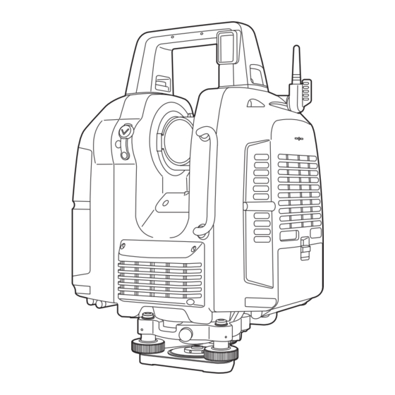
4. PRODUCT OUTLINE 4.1 Parts of the Instrument Handle Scanner unit (laser aperture) Camera (telescope) Wide-angle camera (with lens cap) Sighting collimator Instrument height mark Side handle Heat vents Battery Heat vents cover lever Battery cover Left Stylus (pen) Battery connector Levelling base locking screw Leveling screw... - Page 13 4. PRODUCT OUTLINE Instrument center mark Handle locking screw Laser plummet window Instrument height mark Display Operation key Battery cover lever Battery cover Right Card slot (inside of a battery cover) Side handle Tribrach fixing lever Circular level...
-
Page 14: Operating Keys
4. PRODUCT OUTLINE 4.2 Operating Keys The operating keys on the side of the instrument are as follows: Screen Power key Collimating Position Setting key Start/Stop Scan key Power Indicator Key / Indicator name Function Collimating Position Setting key Sets the collimating position. Start/Stop Scan key Starts or stops scanning. -
Page 15: Display And Functions Of The Main Menu
4. PRODUCT OUTLINE 4.3 Display and Functions of the Main Menu Icons for frequently used functions and various setting modes are displayed on the main menu. Station Setting button Station name Battery icon Data View icon Tilt Setting icon SetUp icon SD Card icon Config icon Scan Setting icon... -
Page 16: Flow Of The Screens
4. PRODUCT OUTLINE 4.4 Flow of the Screens The following illustrates the main flow of the screens. Use a stylus pen to operate the screen. • Do not scratch or use any sharp objects other than a stylus pen on the screen face. Power ON Main Menu SetUp Screen... -
Page 17: Preparations Before Use
5. PREPARATIONS BEFORE USE 5.1 Inserting an SD memory card and Installing the Battery • The station information and the measured data are stored in the SD memory card. Make sure that the SD memory card is inserted before measuring. •... - Page 18 5. PREPARATIONS BEFORE USE 2. Insert a SD card to the card slot. • Please make sure you have the front and back of the SD card facing correctly when inserting into the card slot. • When removing the SD card, press the center of the card slowly.
- Page 19 5. PREPARATIONS BEFORE USE 5. Open the battery cover (left). 6. Similarly, Install two batteries. • Never remove the backup memory in the battery Backup cover (Left). memory 7. Close the battery cover (Left). A click is heard when the cover is secure.
-
Page 20: Connecting The External Power Source
5. PREPARATIONS BEFORE USE 5.2 Connecting the External Power Source Use the external power source if necessary. PROCEDURE Connect the external power source 1. Connect the clip of the external Red clip (+) power cable PC-26 (Sold separately) to a terminal of commercial external Terminal PC-26 power source. -
Page 21: Overview Of Scanning Procedure
5. PREPARATIONS BEFORE USE 5.3 Overview of Scanning Procedure The following describes the overview of scanning procedure: Prepare for scanning 1. Install the instrument “6.4 Setting Up the Instrument” 2. Turn the power ON. “6.3 Power ON/OFF” 3. Set up this instrument. ... -
Page 22: Preparation For Measurement
6. PREPARATION FOR MEASUREMENT 6.1 Detaching / attaching the Handle The carrying handle can be removed from the instrument. To remove it, loosen the 2 handle rocking screws. • Remove the handle when scanning around the zenith or the whole circumference. •... -
Page 23: Power On/Off
6. PREPARATION FOR MEASUREMENT PROCEDURE Attaching the instrument to the levelling base 1. Check that the tribrach fixing screw has been loosened. 2. Align the alignment piece and the tribrach alignment groove and lower the instrument onto Alignment the levelling base. piece 3. - Page 24 6. PREPARATION FOR MEASUREMENT • Internal Calibration In order to maintain its precision, the instrument will automatically perform internal calibration. The internal calibration will take approximately 2 minutes. Confirm that, after the setup is finished, the positional relationship between the instrument and the tribrach will be as shown in the figure here.
-
Page 25: Setting Up The Instrument
• Level and center the instrument precisely. Level and center the instrument precisely to insure the best performance. • Use tripods with a tripod screw of 5/8 in. diameter and 11 threads per inch, such as the Type E TOPCON wide-frame wooden tripod. Do not use a metallic tripod. - Page 26 6. PREPARATION FOR MEASUREMENT The electronic circular level is displayed. Press , and then the laser plummet beam will be emitted from the bottom of the instrument. “” indicates the bubble in circular level. The line within the electronic circular level is set at ±6'.
-
Page 27: Using The Sd Card
6. PREPARATION FOR MEASUREMENT 6.5 Using the SD Card Tap the SD Card icon to check the detail of the SD card usage. PROCEDURE 1. Press the SD Card icon. The confirmation window will appear. Press [Format] to format the SD card. Press [OK] in the confirmation message window to start the format. -
Page 28: Battery Power Remaining Display
6. PREPARATION FOR MEASUREMENT 6.6 Battery Power Remaining Display Battery power remaining display indicates the power condition. : When using external power source) • The remaining battery level will not be displayed when an external power source is used. Measurement is possible. -
Page 29: Replacing The Batteries During The Power Is On
6. PREPARATION FOR MEASUREMENT 6.7 Replacing the Batteries during the power is ON • When replacing the built-in batteries, replace all four batteries with fully charged batteries. • Replace two batteries at a time: Replace A1 and A2 batteries first, and then B1 and B2 batteries, all with ... -
Page 30: Entering Numeric And Alphabetic Characters
6. PREPARATION FOR MEASUREMENT 6.8 Entering Numeric and Alphabetic Characters Numerical, uppercase, and lowercase alphabetic characters can be entered when entering a station, an instrument height, or a backpoint. The function of a keyboard is as follows. Inputted characters switch When entering When entering capital letters... -
Page 31: Preparing The Target
Use the target or (single) prism when performing “target scanning”. • Be sure to use the target sheets for the GLS-2000/1500 manufactured by TOPCON. • Select the target sheet (large, medium, small) based on the distance to the object being scanned. - Page 32 6. PREPARATION FOR MEASUREMENT 3. Install the target board (Sold separately) as shown in the illustration. Tighten the settlement screw surely. 4. Put the magnetic target sheet on the target board. At this point, adjust the center marks (4) of the target sheet and the target board exactly. Target board Center mark Center mark...
-
Page 33: Instrument Settings
7. INSTRUMENT SETTINGS Settings for this instrument are set through main menu icons and settings mode ( “8. FLOW OF THE CONFIGURATION SCREEN”). 7.1 Setting the Tilt Sensor ON/OFF When the auto tilt correction function for the vertical and horizontal angles is turned ON, the 2-axis tilt sensor is activated, automatically compensating errors in vertical and horizontal angles due to inclination of the standing axis. - Page 34 7. INSTRUMENT SETTINGS 2. Press [TILT ON.] The tilt is set to OFF. The line within the electronic circular level is set at ±6'. The amount of dislocation will not be displayed when the bubble is beyond the line. 3. Press [OK.] The Tilt Setting icon is switched OFF ( : OK (It is correctable by using the tilt correction function.)
-
Page 35: Camera Settings (Angle Of View And Resolution)
7. INSTRUMENT SETTINGS 7.2 Camera Settings (Angle of view and Resolution) The built-in camera automatically takes photographs of the entire scanning range and saves the photograph data in the image file when scanning. (when selecting “Wide” or “Tele”) The photograph data of the entire scanning range consists of several photographs. As the scanning area becomes wider, the number of photographs taken will increase. -
Page 36: Settings For Scanning Conditions
7. INSTRUMENT SETTINGS 7.3 Settings for Scanning Conditions By changing the scanning settings, measurement that suits the purpose can be carried out. Resolution can be selected from the predetermined resolutions or by entering the desired resolution. 1. Press the Scan Setting icon. ... - Page 37 7. INSTRUMENT SETTINGS (3) Resolution (a desired value) The horizontal and vertical start point angle, end point angle and measurement pitch can be set to a desired value. (Set the start point angle and end point angle in the scan range setting screen ...
- Page 38 7. INSTRUMENT SETTINGS (4) Range mode Range mode settings are as follows. Detail / High Speed / Low Power / Standard / Close Please refer to the following for details. Range mode Cycle of light emission Laser class Distance Detail 120 KHz Laser class 3R Up to 100 m...
-
Page 39: Measuring Distance To The Target Measurement Object
7. INSTRUMENT SETTINGS 7.4 Measuring Distance to the Target Measurement Object An overall distance to the target measurement object that is required when setting the resolution (a desired value) of the scanning parameter in millimeters will be measured as indicated below. (The distance is not required when using the unit of points or degrees.) PROCEDURE 1. - Page 40 7. INSTRUMENT SETTINGS 4. Press to switch the camera to "Tele" and tap the target measurement object. “Explanation of the buttons” on page 61 The instrument will automatically turn to the target measurement object which will be displayed around the middle of the screen. While doing this, the horizontally rotating part and the turn of the scanner unit will be locked.
-
Page 41: Flow Of The Configuration Screen
8. FLOW OF THE CONFIGURATION SCREEN Press the Config icon to enter the Config mode. The following illustrates the flow of the configuration screen. Press the Config icon. [Temp / Press] [EDM Settings] [Prism] [Tilt 0 Set] [Parameter] [PC offset] [PL offset]... - Page 42 8. FLOW OF THE CONFIGURATION SCREEN [Time / Date] [Time / Date] [Calib Date] [LCD ] [Back Light] [Sound] [Sound] [Unit] [Units] [Coord]...
-
Page 43: Setting Temperature And Atmospheric Pressure
8. FLOW OF THE CONFIGURATION SCREEN 8.1 Setting Temperature and Atmospheric Pressure To compensate the measured data, enter the temperature and atmospheric pressure during the measurement. PROCEDURE 1. Press the Config icon. 2. Press [EDM Settings]. 3. Press [Temp/Press]. 4. Enter the temperature and atmospheric pressure, and then press [OK]. -
Page 44: Setting The Prism Constant And Flash Light
8. FLOW OF THE CONFIGURATION SCREEN 8.2 Setting the Prism Constant and Flash Light Set the prism constant to be used and the flash light. PROCEDURE 1. Press the Config icon. 2. Press [EDM Settings]. 3. Press [Prism]. 4. Enter the prism constant, choose ON/OFF of the flash light, and then press [OK]. -
Page 45: Setting The Date And Time
8. FLOW OF THE CONFIGURATION SCREEN 8.3 Setting the Date and Time Set the date and time to record the date in the measurement data. [Setting example] Date: July 11, 2014 Time: 12:00 PROCEDURE 1. Press the Config icon. 2. Press [Time/Date]. 3. -
Page 46: Displaying The Last Calibration Date
8. FLOW OF THE CONFIGURATION SCREEN 8.4 Displaying the Last Calibration Date The date of the last calibration (precision calibration of measurement distance and angle) can be displayed. We recommend performing the precision calibration again within one year from the last calibration date. PROCEDURE 1. -
Page 47: Adjusting The Brightness Of The Display Section
8. FLOW OF THE CONFIGURATION SCREEN 8.5 Adjusting the Brightness of the Display Section Use the backlight if it is hard to look at the display section in the evening or in a tunnel. The level of backlight brightness can be adjusted from OFF to 10. PROCEDURE 1. -
Page 48: Setting The Volume
8. FLOW OF THE CONFIGURATION SCREEN 8.6 Setting the Volume The volume of the sound which can be heard from this instrument can be adjusted as follows. PROCEDURE 1. Press the Config icon. 2. Press [Sound]. 3. Press [Sound]. 4. Adjust the volume with a slider, and then press [OK]. -
Page 49: Selecting The Unit
8. FLOW OF THE CONFIGURATION SCREEN 8.7 Selecting the Unit Select the units as follows. PROCEDURE 1. Press the Config icon. 2. Press [Units]. 3. Press [Unit]. 4. Select the units for “Temperature,” “Pressure,” “Distance,” and “Angle.” Items set and options (* : Factory setting) Temperature: celsius* / fahrenheit Pressure : hPa* / mmHg / inHg... -
Page 50: Selecting The Coordinate System
8. FLOW OF THE CONFIGURATION SCREEN 8.8 Selecting the Coordinate System Select the coordinate system (ENH or NEH) as follows. PROCEDURE 1. Press the Config icon. 2. Press [Units]. 3. Press [Coord]. 4. Select the coordinate system (ENH* or NEH), and then press [OK]. -
Page 51: Handling The Coordinate Point File
8. FLOW OF THE CONFIGURATION SCREEN 8.9 Handling the Coordinate Point File Import the coordinate point file The coordinate point name and the coordinate value described in CSV file format can be imported into the instrument via the SD card. The occupied point name and the occupied point coordinate or the backsight point name and the backsight point coordinate can be selected from the imported coordinate list. - Page 52 8. FLOW OF THE CONFIGURATION SCREEN PROCEDURE How to import a CSV file (coordinate file) in the SD card 1. Press the SetUp icon. 2. Press of the “OCC name” or “BS name“ window. 3. Press [List Import]. 4. Select the CSV file you wish to import, and then press [OK].
- Page 53 8. FLOW OF THE CONFIGURATION SCREEN PROCEDURE How to delete the coordinate list 1. Press the SetUp icon. Press of the “OCC name” or “BS name“ window. 3. Press [List Clear] to delete the coordinate list. The coordinate list will be deleted. ...
-
Page 54: Data Structure In The Sd Card
8. FLOW OF THE CONFIGURATION SCREEN 8.10 Data structure in the SD card Save data in the SD card with the following hierarchy structure. Within the area where the instrument is set, it is possible to extract and measure a certain target. Select the measurement range to measure the target. -
Page 55: Station Settings
9. STATION SETTINGS Data related to measurement, such as an occupied point name, a backsight point name, target data, and 3D data, are stored in the station. • When setting (moving) the instrument, create a new station. Station Backsight point 1 Occupied point 1 Station data are stored in the SD card. -
Page 56: Creating A New Station
9. STATION SETTINGS 9.1 Creating a New Station [Configuration example] Set the station name as [STA0002]. “6.8 Entering Numeric and Alphabetic Characters” PROCEDURE 1. Press 2. Enter the station name (Example: “STA0002”), and then press [Ent] to create the station. “Station0002”... -
Page 57: Setting The Point Name (Occupied Point And Backsight Point)
9. STATION SETTINGS 9.2 Setting the Point Name (Occupied point and Backsight point) The setting of the occupied point name and the backsight point name is required in order to correlate the known point promptly when the coordinates of the measurement target is transformed during a post- processing. - Page 58 9. STATION SETTINGS 4. Press (Instrument height (IH) can also be entered directly.) 5. Press to display an image of the survey point. • In this case, the laser plummet does not turn on. 6. As shown in the image to the right, place the target for instrument height on the survey point.
- Page 59 9. STATION SETTINGS 8. Press next to the backsight point (BS) name, and then select the backsight point name and the coordinate in the same manner as the occupied point. At this point, if you want to change the backsight point name read from the coordinate file, tap the input-editor of the backsight point name and enter a different backsight point name.
- Page 60 Press [OK] in the confirmation message window. • Only the prism or the target sheet for Topcon's GLS- 2000/1500 can be used as the target. • The target sheet used varies depending on the ...
-
Page 61: Importing The Point Name (Occupied Point Or Backsight Point)
9. STATION SETTINGS Importing the point name (Occupied point or Backsight point) After entering the occupied point name and the backsight point name, perform target scanning on the backsight point. When calculating with a PC after measuring, it is possible to set the coordinates of the occupied point and the backsight point. - Page 62 9. STATION SETTINGS 6. Press to switch the camera to "Tele" and tap the target at the backsight point. “Explanation of the buttons” on page 61 The instrument will automatically turn to the object which will be displayed around the middle of the screen.
-
Page 63: Measuring (Scanning)
10. MEASURING (SCANNING) There are two types of scanning: target scanning that only measures the target, and 3D scanning that obtains 3D data. Scanned data will be saved in the Station folder in the SD card. STA0001 (Station data folder) Station information file (sta file format) Point cloud file of back sight (clt file format) 3D coordinate of back sight (trg file format) -
Page 64: Target Scanning
• Only the prism or the target sheet for Topcon's GLS-2000/1500 can be used as the target. • To align the positional information of the data, at least three sets of common target scanned data are required. Place the target on three or more positions that can be collimated from each station. - Page 65 10. MEASURING (SCANNING) Target name 2. Press to switch the camera to "Tele" and tap the target (pt01). “Explanation of the buttons” on page 61 The instrument will automatically turn to the object which will be displayed around the middle of the screen.
- Page 66 10. MEASURING (SCANNING) 4. The scanning results will be displayed. Check the scanning range, and then press [OK]. You will return to the main menu. 5. Similarly, perform steps 1 to 4 until the completion of target scanning the target “pt06.”...
-
Page 67: Recommended Search Width Setting
10. MEASURING (SCANNING) Recommended search width setting Distance to the Search width Target sheet scanning target (m) (degrees) Small 5-10 Small 10-20 Small, medium 20-50 Small, medium, large 50-100 Medium, large 100-200 Large • Select the search width that meets your usage condition. •... -
Page 68: Scanning
10. MEASURING (SCANNING) 10.2 3D Scanning 3D scanning provides 3D data of the scanning target. To start 3D scanning, determine the scanning range, and then configure various settings related to the scanning. When using the data of target scanning, scan the range that includes the common targets that are placed. ... -
Page 69: Performing 3D Range Setting Scanning
10. MEASURING (SCANNING) Performing 3D range setting scanning PROCEDURE Perform scanning by setting the scanning range 1. Press the Scan Setting icon. 2. Press 3. Press to switch the camera to “Tele”. “Explanation of the buttons” on page 61 4. - Page 70 10. MEASURING (SCANNING) 8. Set the density of scanning For details of the setting items and the procedure, “7.3 Settings for Scanning Conditions” 9. Press [OK]. 10. Press the Start Scan button. When “Manual” is chosen for “Exposure” of camera settings, move the exposure value slider Exposure value slider and adjust the brightness.
- Page 71 10. MEASURING (SCANNING) 12. The scanning results will be displayed. Check the scanning range, and then press [OK].
-
Page 72: Performing 3D Whole Circumference Scanning
10. MEASURING (SCANNING) Performing 3D whole circumference scanning PROCEDURE 1. Press the Scan Setting icon. 2. Press 3. Perform the scan setting. For details of the setting items and the procedure, “7.3 Settings for Scanning Conditions” 4. Press [OK]. 5. - Page 73 10. MEASURING (SCANNING) When "Manual" is chosen for "Exposure" of camera settings, move the exposure value slider and adjust the brightness. 6. Press [OK]. • Sometimes “Internal calibration Please wait ...” is displayed. • When is pressed, it will take a while to stop. 7.
-
Page 74: View The Data On The Sd Card
10. MEASURING (SCANNING) 10.3 View the Data on the SD Card The following describes how to view data saved on the SD card. PROCEDURE 1. Press the Data View icon. 2. Select the data you want to view and press [Open]. -
Page 75: Checks And Adjustments
11. CHECKS AND ADJUSTMENTS GLS-2000 is a precision instrument that requires fine adjustments. It must be inspected and adjusted before use so that it always performs accurate measurements. • After long-term storage or transporting the instrument over a long period of time, or if it is thought that a strong impact has been applied to this instrument during the operation, perform inspection and adjustment with extra care. -
Page 76: Tilt Sensor Calibration
11. CHECKS AND ADJUSTMENTS 11.2 Tilt Sensor Calibration Calibrate tilt sensor 0 datum. This adjustment is performed to set the standard position of the tilt sensor. Firmly set the instrument on the stable board before adjusting. PROCEDURE Adjustment 1. Press the Config icon. 2. -
Page 77: Aligning The Laser Plummet Beam With The Instrument Center
11. CHECKS AND ADJUSTMENTS 11.3 Aligning the Laser Plummet Beam with the Instrument Center Adjust the position of the scanner unit when using the laser plummet function to center the instrument. This adjusts the alignment of the laser plummet beam and the center position of the instrument. PROCEDURE Checking and adjusting 1. - Page 78 11. CHECKS AND ADJUSTMENTS 5. Rotate the instrument horizontally. • Laser beam does not draw a circle -No adjustment necessary • Laser beam draws a circle - The following adjustment necessary 6. Turn the scanner unit manually and carry out the rough alignment so that the laser beam does not draw a circle.
-
Page 79: Aligning The Center Of The Instrument And That Of The Image
11. CHECKS AND ADJUSTMENTS 11.4 Aligning the Center of the Instrument and that of the Image Align the center position of the instrument and that of the displayed image. This enables to align the survey point and the center of the displayed image after aligning the center position of the instrument and the survey point. - Page 80 11. CHECKS AND ADJUSTMENTS 5. Tap on the screen and move the cross- hairs near the survey point. 6. Use the directional buttons at the left, right, top and bottom to align the cross- hairs with the survey point precisely. Press [OK] after the adjustment is complete.
-
Page 81: Battery Charging
12. BATTERY CHARGING 12.1 Battery Charging • The battery was not charged at the factory. Charge the battery fully before using the instrument. • The charger will become rather hot during use. This is normal. • Do not use to charge batteries other than those specified. •... - Page 82 12. BATTERY CHARGING 5. Remove the battery and unplug the charger. • Slots 1 and 2: The charger starts charging the battery mounted first. If you place two batteries in the charger, the battery in slot 1 is charged first, and then the battery in slot 2. ( step 2) •...
-
Page 83: How To Store
13. HOW TO STORE After using the instrument, store it as shown below. Battery charger Battery (BDC70) (CDC68A) GLS-2000 Tool pouch • Power cable • SD card • Target for measuring instrument height Battery (BDC70) -
Page 84: Optional Accessories
14. OPTIONAL ACCESSORIES The following are optional accessories which are sold separately from the instrument. Power cable PC-26 Connect with a commercial external power source. Power cable PC-26 Target board (Large, Small) Place the target sheet (magnet type) and attach to the prism holder. -
Page 85: Warning And Error Messages
15. WARNING AND ERROR MESSAGES The following is a list of the error and warning messages displayed by the instrument and the countermeasures of each message. If the same message is repeated, the instrument has malfunctioned. Contact your local dealer. 15.1 Error Typical error Message... -
Page 86: Warning
15. WARNING AND ERROR MESSAGES 15.2 Warning Type Message Countermeasures Description An error occurred during Check that the SD card is Format failed. SD card formatting. inserted correctly. If the error persists, format the card using a PC with the SD format tool pro- vided by the SD Association on the web. - Page 87 15. WARNING AND ERROR MESSAGES Type Message Countermeasures Description H Interval too small. Please set again The starting point and end point of the designated scan Designate a wider range. V Interval too small. range are too close together. Please set again Cannot scan the target.
-
Page 88: Specifications
16. SPECIFICATIONS Methods Distance measurement : Pulse method Angle measurement : Incremental method General Size : 293 (W) ×152 (D) × 411.5 (H) mm Weight : 10 kg (with battery, tribrach) Instrument height : 226 mm (from the attaching surface of the tribrach to the center of the rotating mirror) Operation temperaturerange : -5 °C to 45 °C... - Page 89 16. SPECIFICATIONS Prism (Single prism) Detection accuracy : 6" (σ) (at 50 m) *1) Differs depending on weather condition and atmospheric stability. *2) Differs depending on the reflectivity and surface condition of the scanning target. *3) Differs depending on range mode. Camera Unit Telescopic camera Number of effective pixels...
- Page 90 16. SPECIFICATIONS Charger (CDC68A) Input voltage : AC100 to 240 V Charging time per battery (at 25°C) BDC70 : about 5.5 hours (Charging can take longer than the times stated above when temperatures are either especially high or low.) Charging temperature range : 0 to 40 °C Storage temperature range : -20 to 65 °C...
-
Page 91: Regulations
17. REGULATIONS Region/ Directives/ Labels/Declarations Country Regulations California, Proposition 65 U.S.A California, Perchlorate U.S.A Material (CR Lithium Battery) California Recycling and NY, Batteries U.S.A. - Page 92 Hereby, TOPCON CORP., declares that the above-mentioned equipment is in compliance with the essential requirements and other relevant provisions of Directive 1999/5/EC. Please inquire below if you wish to receive a copy of Topcon’s Declaration of Conformity. Topcon Europe Positioning B.V.
- Page 93 17. REGULATIONS Region/ Directives/ Labels/Declarations Country Regulations EU Battery Directive...
- Page 94 Please see the attached address list or the following website for contact addresses. GLOBAL GATEWAY http://global.topcon.com/ © 2014 TOPCON CORPORATION ALL RIGHTS RESERVED...
Need help?
Do you have a question about the GLS -2000 Series and is the answer not in the manual?
Questions and answers