Table of Contents
Advertisement
Quick Links
Operation and Service Instructions
Dual Tank
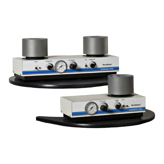
MicroBlaster® MB1002
Issue Date: July 2016
This manual covers all of the variations of the MB1002 series
manufactured after July 14, 2016 (MB1002-1, MB1002-2, ETC)
Comco Inc.
2151 N. Lincoln Street
Burbank, California 91504
USA
Phone: 818-841-5500
www.comcoinc.com
Book P/N MB1247-1
File: MB1002.doc
Advertisement
Chapters
Table of Contents

Related Manuals for Comco MicroBlaster MB1002 Series

Summary of Contents for Comco MicroBlaster MB1002 Series
- Page 1 Dual Tank MicroBlaster® MB1002 Issue Date: July 2016 This manual covers all of the variations of the MB1002 series manufactured after July 14, 2016 (MB1002-1, MB1002-2, ETC) Comco Inc. 2151 N. Lincoln Street Burbank, California 91504 Phone: 818-841-5500 www.comcoinc.com Book P/N MB1247-1...
- Page 2 Congratulations! The Comco MicroBlaster® you have purchased is equipped with the latest features to make it simple to operate and easy to maintain. The addition of the auto-vent component means it is no longer necessary to manually vent air from the unit after turning the power off.
-
Page 3: Table Of Contents
Table of Contents The Comco Warranty ....................v Safety Precautions .....................vi Section 1: The MicroBlaster MB1002 ............1-1 This section introduces you to the basic unit, including its description, principles of operation, and detail specifications. Overview ......................1-2 Figure 1-1, MicroBlaster MB1002 ............1-2 How The MicroBlaster Works ................1-3... - Page 4 MicroBlaster MB1002 and workstations. Appendix A: Parts Lists .....................A-1 Major Assemblies and Principal Parts ............A-2 Standard Accessory Parts ................A-6 Optional Parts ....................A-7 Recommended Spares ..................A-8 Appendix B: Drawings and Schematics ..............B-1 Appendix C: Workstations ..................C-1 Comco Inc. Issue Date: July 2016...
-
Page 5: The Comco Warranty
The warranty period begins when the equipment ships from the Comco facility and applies to the original owner only. Comco is not liable for damages from any cause or use of such equipment beyond the cost of repairing any defective parts. -
Page 6: Safety Precautions
General issues involved in operating machinery. Working with a Device that is Pressurized The MicroBlaster uses pressurized air to perform its basic function. To minimize the risk of an accident related to air pressure, Comco also recommends the following: √... - Page 7 The MicroBlaster uses several types of abrasive media that should not be inhaled or ingested in large quantities or maintained in prolonged contact with the skin. When working with the abrasive media, Comco recommends the following: √ Do not direct the abrasive blast on bare skin or face/eyes.
- Page 8 Also, always fill the tank through the flapper valve to greatly reduce the amount of wear on the threads. Material safety data sheets (MSDS’s) for all abrasives distributed by Comco are available from the Comco factory. Every powder shipment includes an MSDS.
- Page 9 Avoiding Hazards Associated with Operating Machinery The following warning labels/pictograms are utilized in the MicroBlaster CE (European) versions: Symbol Meaning ELECTRICAL HAZARD HAND PROTECTION RECOMMENDED WHERE APPROPRIATE EYE PROTECTION RECOMMENDED WHERE APPROPRIATE RESPIRATORY PROTECTION RECOMMENDED WHERE APPROPRIATE Comco Inc. Issue Date: July 2016...
-
Page 11: Section 1: The Microblaster Mb1002
Section 1: The MicroBlaster MB1002 Section 1: The MicroBlaster MB1002 In This Section This section gives you an overview of your MicroBlaster including: A general description of the MicroBlaster. How the MicroBlaster Works. Detail specifications. Comco Inc. Issue Date: July 2016... -
Page 12: Overview
MicroBlaster MB1002 Overview The Comco MicroBlaster® model MB1002 is a compact bench-top machine that delivers a precisely controlled stream of micro-abrasive particles at high velocity. With the appropriate abrasive powder and the necessary adjustments, it will clean, deburr, cut or drill any material, particularly hard or brittle ones. -
Page 13: How The Microblaster Works
What happens when the machine is actually in operation is explained on the following pages. Comco Inc. Issue Date: July 2016... - Page 14 Since the air flowing from the regulator into the mixing chamber is at basically the same pressure as that in the tank, the upward force of air keeps the abrasive in the tank. At this point, little or no abrasive is being injected into the air stream. Comco Inc. Issue Date: July 2016...
- Page 15 Additional information regarding the tank orifice, nozzle sizes, abrasives, and other variables in the abrasive blast process is presented in Section 3 of this manual. Comco Inc. Issue Date: July 2016...
-
Page 16: Detail Specifications
80 psig; and nozzle life will be 8 to 35 hours depending on the amount of wear that can be tolerated. Operating voltage specified by order and as shown on nameplate. Comco Inc. Issue Date: July 2016... -
Page 17: Section 2: Getting Started
MicroBlaster, including: The work area required to properly use the MicroBlaster. What you received with the MicroBlaster. Basic Components of the MicroBlaster. Setting up and testing the MicroBlaster. Comco Inc. Issue Date: July 2016... - Page 18 The propellant required for the abrasive is compressed air or neutral gas that meets the Detail Specifications outlined in Section 1. Comco has a complete line of air dryers for shop (compressed) air supplies that will meet or exceed those specifications.
- Page 19 MB1002. If the WS2200 or WS6000 WorkStation is used, it requires 40 watts. The DC2100 Dust Collector, if used, requires about 16 amps for its 1-HP motor. Actual voltage required for each machine will be found on the nameplate. Comco Inc. Issue Date: July 2016...
- Page 20 You may use this tip sheet to quickly get your MicroBlaster set up and ready to operate, and as a ready reference for common questions regarding the operation of the MicroBlaster. Keep it nearby and refer to it often. For complete details on the MicroBlaster, Comco strongly urges you to read the manual completely.
- Page 21 Hi/Performance nozzle, MB1520-30 (green), and a .046” nozzle, MB1520-46 (yellow), should already be installed on the MicroBlaster MB1002. Open all small packages within the large carton carefully, since many small parts are included with the shipment. Comco Inc. Issue Date: July 2016...
- Page 22 “OFF” and unit has vented. Pinch Assemblies The Pinches are located on the rear panel of the MicroBlaster. The pinch squeezes the blue poly hose in order to stop the flow of air and abrasive. Comco Inc. Issue Date: July 2016...
- Page 23 Air Pressure Control Control Power Switch Powder Flow Control Pressure Gauge Handpieces & Nozzles FRONT VIEW "Quick Fill" Flapper Valve Tank Cover Pinch Vent Hose Air Fitting Pinch Footswitch Cord REAR VIEW Vent Hose Comco Inc. Issue Date: July 2016...
-
Page 24: Setup And Test
The MicroBlaster can be manufactured for either 115VAC or 230VAC. Check the voltage on the nameplate located on the back panel to see which voltage is correct for your machine. 6. Place the footswitch in any convenient position for the operator. Comco Inc. Issue Date: July 2016... - Page 25 14. You are now ready to select the proper abrasive, nozzle and other operational parameters to begin using your MicroBlaster. These issues, as well as detailed operational instructions, are discussed in the next section. Comco Inc. Issue Date: July 2016...
- Page 26 Section 2: Getting Started MicroBlaster MB1002 THIS PAGE INTENTIONALLY BLANK Comco Inc. 2-10 Issue Date: July 2016...
-
Page 27: Section 3: Using The Microblaster
Section 3: Using the MicroBlaster Section 3: Using the MicroBlaster In This Section This section tells you how to efficiently operate your MicroBlaster, including: Abrasive selection. Orifice and Nozzle selection. General operation of the MicroBlaster. Comco Inc. Issue Date: July 2016... - Page 28 Powder Flow Adjustment Setting Bypass orifice Table 3-1 gives a brief overview of all of these essential factors. Each of them is discussed in detail on the following pages, beginning with abrasive selection. Comco Inc. Issue Date: July 2016...
- Page 29 This is an optional device inserted into the See the Bypass Orifice abrasive tank bypass tube that may be used to Orifice heading within increase abrasive flow, ultimately resulting in this section. faster cutting action. Comco Inc. Issue Date: July 2016...
-
Page 30: Abrasive Selection
“clump up”, preventing a free flow from the tank. Problems associated with moisture in the abrasive powder are discussed in detail in Section 4. Comco Inc. Issue Date: July 2016... - Page 31 NOTE: Always start the work shift with fresh abrasive powder. Powder left sitting in an un-pressurized machine overnight can absorb moisture. This contaminated powder can cause flow problems. Keep powder containers sealed and stored in a cool, dry place. Comco Inc. Issue Date: July 2016...
- Page 32 Refer to the table above to determine the size. The tank orifice should be installed finger tight only with a 1/4” nut driver (see Figure 3-1). For improved performance and longer life, all Comco orifices are carbide lined. Comco Inc.
- Page 33 30 - 80 0.025 0.006 65 - 200 0.030 0.008 80 - 300 0.040 0.010 150 - 300 0.060 Tank Orifice 1/4" Nut Driver Bypass Orifice (Optional) Bypass Tube Figure 3-1: Changing the Tank Orifice Comco Inc. Issue Date: July 2016...
- Page 34 With larger nozzle openings, more abrasive can flow, and thus cutting speed is increased and efficiency will improve. Comco offers many different sizes and configurations (see Figure 3-2 and Table 3-4), from a 0.015" diameter round nozzle, to 0.012" x 0.150" rectangular. For most applications a round nozzle would be preferred due to the precise spray pattern.
- Page 35 .074 .018 - .025 10 - 50 Fan, Small cuts Dimensions are in inches unless noted otherwise. Used for special circumstances only. Overall width is approximately 1/2”. Standard Nozzle thread configuration is 10-32. Comco Inc. Issue Date: July 2016...
- Page 36 In this manner, a saw cut may be made with relatively straight sides through relatively thick materials. In any case, nozzle angle can be adjusted in two planes to result in at least one side being cut perpendicular to the surface. Comco Inc. 3-10 Issue Date: July 2016...
- Page 37 A significant increase in abrasive flow does not always increase the speed at which parts can be processed. The micro-abrasive blasting process is optimized to work with less abrasive, using air flow and particle velocity to improve efficiency. Please contact Comco's Technical Support team for assistance in fine-tuning your abrasive blasting process. Comco Inc.
-
Page 38: General Operation Of The Microblaster
Section 2. √ Selected the proper abrasive for your application. √ Installed the proper tank orifices for the abrasive powders you are using. √ Selected the proper nozzles for your application. Comco Inc. 3-12 Issue Date: July 2016... - Page 39 5. Maintain a generous loop in the abrasive hose between the abrasive pinch valve and the hose connection on the rear panel. Figure 3-3: Filling the Abrasive Tank Comco Inc. 3-13 Issue Date: July 2016...
- Page 40 Air Pressure Control Control Power Switch Powder Flow Control Pressure Gauge Handpieces & Nozzles FRONT VIEW "Quick Fill" Flapper Valve Tank Cover Pinch Vent Hose Air Fitting Pinch Footswitch Cord REAR VIEW Vent Hose Comco Inc. 3-14 Issue Date: July 2016...
- Page 41 Refer to Table 3-1 and the beginning of this section for factors that affect abrasive blasting results. Comco Inc. 3-15 Issue Date: July 2016...
- Page 42 Changing the Abrasive 1. Turn Power “OFF” and release pressure (see steps 1 and 2, above). 2. Unscrew and remove the tank cover (it is best to only work with one tank at a time). Comco Inc. 3-16 Issue Date: July 2016...
- Page 43 Note: Always start the work shift with fresh abrasive powder. Powder left sitting in an unpressurized machine over night can absorb moisture. This contaminated powder can cause flow problems. Keep powder containers sealed and stored in a cool, dry place. Comco Inc. 3-17 Issue Date: July 2016...
- Page 44 Section 3: Using the MicroBlaster MicroBlaster MB1002 THIS PAGE LEFT INTENTIONALLY BLANK Comco Inc. 3-18 Issue Date: July 2016...
-
Page 45: Section 4: Maintenance
Section 4: Maintenance In This Section This section tells you how to maintain your MicroBlaster in peak operating condition, including: Maintenance intervals. Extending the life of wear items. Replacing worn out components. Comco Inc. Issue Date: July 2016... -
Page 46: Normal Maintenance
The maintenance intervals given in this section are intended for use as guidelines only. The machine’s frequency of use will determine how often these maintenance items will need to be performed. Contact Comco if you have questions. Note the following cautions before beginning any maintenance or repair task: ... - Page 47 Comco recommends that these parts be replaced annually, or every 2000 hours of operation, whichever comes first. Establishing and following a regularly scheduled maintenance program for your equipment, can reduce costly downtime.
-
Page 48: Parts Subject To Normal Wear
Tank Orifice The orifices control the amount of abrasive deposited into the mixing chambers. Over time, the orifices may become enlarged, allowing too much abrasive powder into the air stream, causing clogging of small nozzles. Comco Inc. Issue Date: July 2016... - Page 49 (see Figure 4-1). Abnormal hose breakage, always at the pinch, is an indication of pinch tube or plunger failure. See Section 5 for replacement procedures. Figure 4-1: Pinch Tube and Plunger Inspection Comco Inc. Issue Date: July 2016...
- Page 50 At weekly intervals (or as necessary), spray or wipe a dry lubricant such as graphite, molycote, or Teflon powder on the tank threads (order Comco P/N ST8062). If an aerosol dispenser is used, or the lubricant is suspended in a solvent, allow a few minutes for the solvent to dry before installing the cover.
-
Page 51: Leaks
Other types of air dryers should be checked according to the manufacturer’s recommendations. Check the system air dryer on a regular basis. Typically, this should be done monthly. However, in high use facilities, it should be done weekly. Comco Inc. Issue Date: July 2016... -
Page 52: Moisture
Comco maintains an extensive library of technical bulletins that address issues including the effects of moisture on the micro-abrasive blasting process and methods for reducing moisture contamination. -
Page 53: Section 5: Trouble-Shooting And Repair
How to correct most problems that may develop with the MicroBlaster. How to contact Comco’s Customer Service Department. How to order replacement parts for the MicroBlaster. Comco Inc. -
Page 54: Trouble-Shooting
NOTE: Improper repairs may void your warranty. If you have any questions, consult with Comco before you do any work on the inside of the MicroBlaster MB1002. Most problems that can occur with your MicroBlaster will fall into either one of two categories: No air flow - Nothing happens when you depress the footswitch. -
Page 55: How To Order Replacement Parts
Providing this information will expedite your request and will also ensure that you receive the proper component for your unit. Comco offers a Repair Kit for its customers who prefer to do their own maintenance. This kit contains the parts and instructions needed to keep your MicroBlaster in top condition. -
Page 56: Common Problems, Causes, And Solutions
The abrasive hose should slide freely opening? through the abrasive pinch tube when the footswitch is actuated. If it does not, the valve is not functioning properly. See maintenance of the pinch valve below. Comco Inc. Issue Date: July 2016... - Page 57 Always start the work shift with fresh abrasive powder. Powder left sitting in an unpressurized machine overnight can absorb moisture. This contaminated powder can cause flow problems. Keep powder containers sealed and stored in a cool, dry place. Comco Inc. Issue Date: July 2016...
- Page 58 Remove and save the Quicknut and rubber grommet from the old hose. Pull the hose through the pinch tube. Inspect the hose connector for wear and replace if necessary. Inspect the pinch tube and pinch plunger as described in the following pages. Comco Inc. Issue Date: July 2016...
- Page 59 Tighten with a 7/16" open end wrench. Slide the Quicknut onto the hose and work the end of the hose onto the new connector. Tighten the Quicknut onto connector. Hand tighten only. Comco Inc. Issue Date: July 2016...
-
Page 60: Inspecting And Repairing The Pinch Valve
(see replacement procedure, “Abrasive Hose”, above). Remove the pinch tube. Inspect it for sharp edges or pitting due to abrasive leakage. Replace if necessary with Comco part number MB1282. Inspect the pinch plunger for sharp edges or pitting due to abrasive leakage. - Page 61 Reconnect the air hose. Make sure it is firmly in place. Replace the wires to the terminal board (polarity is not important). Install the abrasive hose (see Replacing Abrasive Hose procedure above). Replace the cover. Comco Inc. Issue Date: July 2016...
-
Page 62: Inspecting And Repairing The Modulator
13. Note: Make sure the core is inserted properly into the housing. The cross-holes must be nearest the tank. Comco Inc. 5-10 Issue Date: July 2016... - Page 63 MicroBlaster MB1002 Section 5: Trouble-Shooting and Repair Figure 5-1: Modulator Assembly and Modulator Housing Assembly MODULATOR ASSEMBLY --------------------------------------------------------------------------------------------------------------------- MODULATOR HOUSING ASSEMBLY Comco Inc. 5-11 Issue Date: July 2016...
- Page 64 If so, you have a moisture problem. See Section 4, “Moisture”, on how to prevent moisture from contaminating your powder. Comco Inc. 5-12 Issue Date: July 2016...
-
Page 65: Clogging
Note: It is very hard to detect a slight leak in the tank cover. If you cannot locate a leak anywhere else, it is probably the tank cover O-rings. See the following discussion, “Tank Cover”. Comco Inc. 5-13 Issue Date: July 2016... -
Page 66: Air Pressure Regulator
Replace the Regulator Assembly according to the following procedure: Air Pressure Regulator Assembly Replacement Procedure (Refer to Appendix B, Figure 10, or contact Comco for part number.) 1. Turn Power OFF. 2. Remove the MicroBlaster cover (4 screws). 3. Using a 7/16" open-end wrench, remove the hose connector nuts and hoses from the regulator assembly. -
Page 67: Tank Cover
Tank Cover Flapper Valve The flapper valve allows for quick filling of the abrasive tank. If the valve becomes worn or damaged, replace it with Comco part number MB1145. Tank Cover Flapper Valve Replacement Procedure (MB1145) Turn Power OFF. - Page 68 Major Assemblies: List of Appendix A, Parts Lists and principal parts of the Appendix B, Drawings and MicroBlaster with break-down. Schematics Parts Details: Includes Appendix B, Drawings and functional, electrical, and Schematics pneumatic schematics. Comco Inc. 5-16 Issue Date: July 2016...
-
Page 69: Section 6: Optional Equipment
MicroBlaster MB1002 Section 6: Optional Equipment Section 6: Optional Equipment In This Section Optional equipment available on your MicroBlaster Operation and service of these options Comco Inc. Issue Date: July 2016... - Page 70 Section 6: Optional Equipment MicroBlaster MB1002 THIS PAGE LEFT INTENTIONALLY BLANK Comco Inc. Issue Date: July 2016...
-
Page 71: Appendix A: Parts Lists
MicroBlaster MB1002 Appendix A: Assemblies, Components, and Parts Appendix A Parts Lists for the MicroBlaster MB1002 Comco Inc. Issue Date: July 2016... -
Page 72: Major Assemblies And Principal Parts
Coupler, 1/8" P ST4049 Nipple, 1/8" P ST4166 Connector, 1/4T x 1/8MPT, Push-In MB1233 Hose, Abrasive 12 ft. Tank Orifice size may be changed by Sales Order. 230V Assy is MB1198-10; Valve is ST6013-5 Comco Inc. Issue Date: July 2016... - Page 73 230V Assy is MB1290-8, Coil is MB1310-2 230V Assy is MB1298-4, Coil is ST6003-5 230V Assy is MB1321-6, Coil is ST6003-5 * Non-standard parts. See individual part drawings, Appendix B, for information on choosing correct part numbers. Comco Inc. Issue Date: July 2016...
- Page 74 Tube, plastic 1/4” ST4012 ST7625-010 Fuse, 1 amp 230 V parts are: Socket MB1227-2; Cord ST7235; Fuse ST7625-005. * Non-standard parts. See individual part drawings, Appendix B, for information on choosing correct part numbers. Comco Inc. Issue Date: July 2016...
- Page 75 (cont’d) MAJOR ASSEMBLIES AND PRINCIPAL PARTS PART NUMBER DESCRIPTION QTY. MB1520-30 Hi/Performance Nozzle, .030, Green ST5020 O-ring, Nozzle MB1520-46 Hi/Performance Nozzle, .046, Yellow ST5020 O-ring, Nozzle ST5465-4 Pin, Spring, 0.062" x 0.250" Comco Inc. Issue Date: July 2016...
-
Page 76: Standard Accessory Parts
Bushing, .250T x.125P, Brs ST4166 Connector, 1/4T x 1/8P Tube, Nylon, 1/4” ST4012 6 ft ST5066 Funnel, Abrasive ST7625-010 Fuse, 1 Amp Kit for 230V machines is MB1089-2; Fuse is ST7625-005; Nut Driver ST5114 is added. Comco Inc. Issue Date: July 2016... -
Page 77: Optional Parts
Opt. MB1409-18 Orifice, Tank, .018 Opt. MB1409-30 Orifice, Tank, .030 Opt. MB1409-46 Orifice, Tank, .046 Opt. MB1500-10, etc. Nozzles, Standard, Various Opt. (See Section 3) MB1520-30, etc. Nozzles, Hi Performance Opt. (See Section 3) Comco Inc. Issue Date: July 2016... - Page 78 Abrasive Hose 25 ft. MB1230-1 Handpiece Nose MB1455 Connector, Quicknut ST5022 O-ring Cover Seal ST5624 O-ring, Flapper Seal Orifice and Nozzle sizes are determined by application requirements. Refer to Section 3 for details. Comco Inc. Issue Date: July 2016...
-
Page 79: Appendix B: Drawings And Schematics
MicroBlaster MB1002 Appendix B: Drawings and Schematics Appendix B Drawings and Schematics for the MicroBlaster MB1002 Comco Inc. Issue Date: July 2016... - Page 80 Figure 9: P/N MB1298-3 (-4) Abrasive Pinch Assembly ..........B-12 Figure 10: P/N MB1321-5 Air Pressure Regulator ............. B-13 Figure 11: P/N MB1198-9 (-10) Air Valve Assembly ..........B-14 Figure 12: P/N MB1456-3 (-4) Tank Extender Kit ............B-15 Comco Inc. Issue Date: July 2016...
-
Page 81: Figure 1: Front View
ST7003 Tank Switch ST7159 Indicator Lamp ST7004 Air Pressure Reg. Powder Flow Right MB1397-1 Abrasive Tank Left Powder Flow Left MB1397-2 Abrasive Tank Right Knob Assy MB1396 See individual Part Drawing for Part Numbers. Comco Inc. Issue Date: July 2016... -
Page 82: Figure 2: Top View
(MB1409-25) in the right tank, and a 0.040” diameter orifice (MB1409-40) in the left tank. Tank Orifice size may be changed. Refer to Section 3 of the Manual. See individual Part Drawing for Part Number. Comco Inc. Issue Date: July 2016... -
Page 83: Figure 3: Pneumatic Schematic
MicroBlaster MB1002 Appendix B: Drawings and Schematics FIGURE 3: PNEUMATIC SCHEMATIC, MODEL MB1002 Comco Inc. Issue Date: July 2016... - Page 84 Appendix B: Drawings and Schematics MicroBlaster MB1002 FIGURE 4A: ELECTRICAL SCHEMATIC, MODEL MB1002 Comco Inc. Issue Date: July 2016...
- Page 85 MicroBlaster MB1002 Appendix B: Drawings and Schematics FIGURE 4B: ELECTRICAL SCHEMATIC, MODEL MB1002-CE Comco Inc. Issue Date: July 2016...
-
Page 86: Figure 5: P/N Mb1568 Tank Cover Assembly
Appendix B: Drawings and Schematics MicroBlaster MB1002 FIGURE 5: P/N MB1568 TANK COVER ASSEMBLY Item Description Part No. Flapper, Assy MB1145 O-ring, Cover Seal ST5022 O-ring, Flapper Seal ST5624 Comco Inc. Issue Date: July 2016... -
Page 87: Figure 6: P/N Mb1404-15 (-16) Abrasive Tank Assembly
Elbow, St, .125P, 45° ST4130 Right Tank Assy MB1404-15 shown. Left Tank Assy MB1404-16 is mirror image. MB1404-15 and MB1404-16 have Acme style tank cover threads. Tank Orifice size may be changed. See Section 3. Comco Inc. Issue Date: July 2016... -
Page 88: Figure 7: P/N Mb1290-7 (-8) Modulator Assembly
Yoke, Coil MB1287 Body,Modulator [2] MB1482 Term, Fork, Crimp ST7010-1 MB1290-7 is 115V, MB1290-8 is 230V. Items 3, 4, 5,& 6, are part of item 1. MB1310-1 is 115V Coil, MB1310-2 is 230V Coil. Comco Inc. B-10 Issue Date: July 2016... -
Page 89: Figure 8: P/N Mb1083-3 Handpiece Assembly
Handpiece Tube MB1012-6 [1] Quicknut Connector (Ref) MB1455 Handpiece Nose MB1230-1 [1] Grommet, Rubber (Ref) ST5010 Abrasive Hose MB1233 O-ring ST5020 MB15xx- (as req’d) Abrasive Nozzle MB1083-3 includes items 1, 2 & 3 only. Comco Inc. B-11 Issue Date: July 2016... -
Page 90: Figure 9: P/N Mb1298-3 (-4) Abrasive Pinch Assembly
ST4003 Cylinder, 1 1/8 ST6081 Elbow, 1/4T x 1/8P ST4144 Ell, Male 1/4T x 1/8P ST4010 Tee, M. 1/4T x 1/8P ST4150 MB1298-3 is 115V, MB1298-4 is 230V. For 230V, Use Valve ST6003-5. Comco Inc. B-12 Issue Date: July 2016... -
Page 91: Figure 10: P/N Mb1321-5 Air Pressure Regulator
Ell, StreeT, 1/8 NPT ST4004 Tee, Male, 1/4Tx1/8T ST4018 Elbow, 90° Union,1/8T ST4246 Vent, Breather, 1/8 P ST4003 Nipple, 1/8P x 1.25 ST4050 MB1321-5 is 115V, MB1321-6 is 230V For 230V, Use Valve ST6277-2. Comco Inc. B-13 Issue Date: July 2016... -
Page 92: Figure 11: P/N Mb1198-9 (-10) Air Valve Assembly
Conn. Male, 1/4T x 1/8P ST4166 Nipple, Close, .125 ST4049 Valve, Sol, 115V [2] ST6013-1 Term. Fork, Crimp ST7010-1 Coupling, .125P ST4029 MB1198-9 is 115V, MB1198-10 is 230V. For 230V, use valve ST6013-5. Comco Inc. B-14 Issue Date: July 2016... - Page 93 [1] 5" Tank Extender Kit is shown, 10" Tank Extender Kit is P/N MB1456-4. MB1456-3 and MB1456-4 Extender Kits have Acme style tank cover threads. [2] Bypass Tube is part of Tank Extender Assembly. Comco Inc. B-15 Issue Date: July 2016...
- Page 94 Appendix B: Drawings and Schematics MicroBlaster MB1002 THIS PAGE LEFT INTENTIONALLY BLANK Comco Inc. B-16 Issue Date: July 2016...
-
Page 95: Appendix C: Workstations
MicroBlaster MB1002 Appendix C: Workstations Appendix C Workstations Comco Inc. Issue Date: July 2016... - Page 96 The Comco WS2200 and WS6000 WorkStations are designed to work as part of a micro- abrasive blasting system consisting of the following: 1.
- Page 97 CAUTION: Failure to secure the free end of the vent hoses may allow them to fall out of the workstation and potentially whip around if left unsecured. Always secure the free ends of the hoses. Comco Inc. Issue Date: July 2016...
- Page 98 1. Unplug unit Switch failed 2. Remove back panel 3. Using ohmmeter, test for continuity across switch terminals with the switch set to ON. Service dust collector Dust builds up inside Comco Inc. Issue Date: July 2016...
- Page 99 Workstations with 5/8" dia holes in panels use Grommet P/N ST5311 Older workstations (S/N below 4460) use 4" Iris P/N WS2028-1 For 230V CE compliant workstations use Ballast No. ST7239-3. Standard replacement lamps are available at most hardware stores. Comco Part No. ST7164 ST7164-1 ST7164-2 Lamp Type...
- Page 100 WS2200 series Classic WorkStation – 115 or 230V For 230V CE compliant workstations see below For workstations equipped with ESD controls see page 7 WS2200 series Classic WorkStation – 230V CE Compliant For workstations equipped with ESD controls see page 7 Comco Inc. Issue Date: July 2016...
- Page 101 MicroBlaster MB1002 Appendix C: Workstations WS2200 series Classic WorkStation with ESD Controls – 115 or 230V For 230V CE compliant workstation see below WS2200 series Classic WorkStation with ESD Controls – 230V CE Compliant Comco Inc. Issue Date: July 2016...
- Page 102 Appendix C: Workstations MicroBlaster MB1002 WS6000 series Clearview WorkStation – 115 or 230V For 230V CE compliant ClearView WorkStation see below WS6000 series ClearView WorkStation – 230V CE Compliant Comco Inc. Issue Date: July 2016...
Need help?
Do you have a question about the MicroBlaster MB1002 Series and is the answer not in the manual?
Questions and answers