Table of Contents
Advertisement
Available languages
Available languages
Quick Links
IO22C02KNXFI01010001.doc
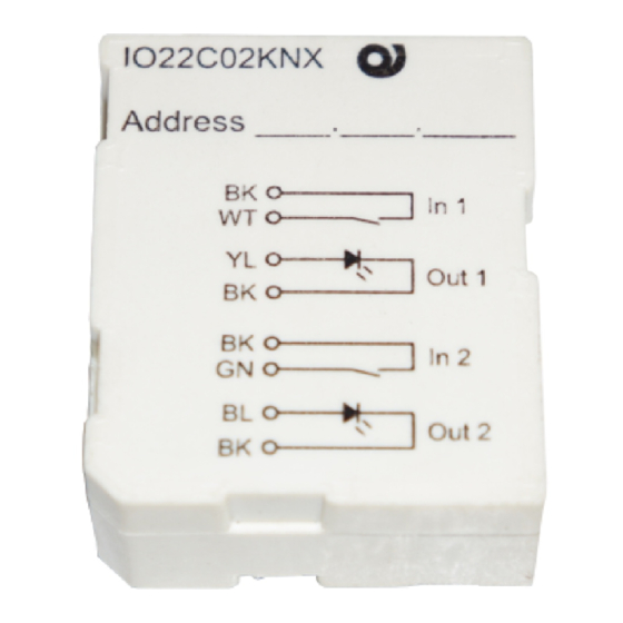
Inwall 2 Input / Output Module
IO22C02KNX
Product and Applications description
The product is dedicated to interfacing free potential contacts
through the 2 input channels, for example sensors, traditional
buttons, etc. and 2 output channels at low voltage for drive
signal lamp or LED for example for synoptic panels used for
monitoring the installation.
The device is equipped with appropriate communication inter-
face with the bus type TP1 (twisted pair) KNX European stan-
dard, according CEI EN 50090.
Application Program
Application Program
Application Program
Application Program
Downloadable from website:
www.eelectron.com
Maximum number of group addresses:
This is the maximum number of different group addresses the
device is able to memorize.
Maximum number of associations:
This is the maximum number of associations between com-
munication objects and group addresses the device is able to
memorize.
Caution: each transmission object has usually associated a
Caution
Caution
Caution
single group address. If you want to associate to a transmis-
sion communication object other addresses in addition to the
first, please note that you can add a maximum of 16 group ad-
dresses of this kind for the whole device.
Technical data
Technical data
Technical data
Technical data
Power Supply:
Via bus EIB/KNX cable
• Voltage
21..30V DC
• Current Consumption EIB/KNX
< 10mA
Input
Input
Input
Input
• Number: 2 free contacts
• Maximum Length of Connecting Cable:
• Voltage Scanning: Vn – 3,3 V DC (internally Generated)
Output
Output
Output
Output
• Number: 2 outputs for drive led – Max 0,5 mA
Control Elements
Control
Control
Control
Elements
Elements
Elements
• Red LED and button EIB/KNX for programming the physical
address
Connections
• EIB/KNX 2 Terminals for connections bus with 0,8mmØ
• Input
2 connector cable to be wired with 24 AWG
• Output
2 connector cable to be wired with 24 AWG
Electrical Pattern
Electrical
Pattern
Electrical
Electrical
Pattern
Pattern
KNX
1
INTERFACE
2
3
4
7
8
9
10
Mechanical Data
Mechanical Data
Mechanical Data
Mechanical Data
• Case: plastic
• Protection class: II in accordance with EN 61140
• Dimensions: (width x height. X depth.): 43 x 36 x 17 mm
• Weight: approx. 30 g
Electrical Safety
• Degree of pollution (IEC 60664-1): 2
• Degree of protection (EN 60529): IP 20
• Protection class (according to IEC 1140): III
30
30
30
30
• Overvoltage class (according to IEC 664-1): III
• Bus: safety voltage SELV DC 24 V
• Meets EN 50090 and IEC 664-1: 1992
30
30
30
30
EMC Requirements
Complied with EN 50081-1, EN 50082-2 and EN 50090-2.2
Terms of use
• According to EN 50090-2.2
• Ambient temperature during operation: 0 ° C + 45 ° C
• Storage temperature: - 20 ° C + 55 ° C
• Relative humidity: max 90%
Certification
Certification
Certification
Certification
EIB/KNX certificate
CE Mark
According to EMC guideline and low voltage directive
≤ 10m
Indicators Position and Control Elements
Indicators Position and Control Elements
Indicators Position and Control Elements
Indicators Position and Control Elements
15
Wired Connectors:
1.
BLACK COMMON INPUT 1
2.
WHITE INPUT 1
3.
YELLOW OUTPUT 1
4.
BLACK COMMON OUTPUT 2
5.
n.c
6.
n.c
7.
BLACK COMMON INPUT 2
8.
GREEN INPUT 2
9.
BLUE OUTPUT 2
10. BLACK COMMON OUTPUT 2
COM1
11. n.c.
12. n.c.
IN1
15. Terminal Connection Bus (graft):
OUT1
- negative pole Black
+ positive pole Red
COM2
Control Unit And Display:
COM3
14. ETS programming led
IN2
13. ETS programming switch
OUT2
COM4
BLACK
WHITE
YELLOW
BLACK
1
2
3
14
4
13
5
BLACK
6
7
GREEN
8
BLUE
9
10
BLACK
11
12
Installation Instructions
The device may be used for permanent indoor installations
in dry locations within wall box mounts.
WARNING
• The device must not be connected to 230V cables
• The prevailing safety rules must be heeded.
• The device must be mounted and commissioned by an
authorised installer.
• The applicable safety and accident prevention regula-
tions must be observed.
• The device must not be opened. Any faulty devices
should be returned to manufacturer.
• For planning and construction of electric installations, the
relevant guidelines, regulations and standards of the re-
spective country are to be considered.
Mounting and Wiring hints
General Description
The device configuration (KNX physical address assign-
ment) is done by pressing the programming push button lo-
cated in the back side of the housing. Please take care dur-
ing installation to leave connection wires long enough in or-
der to remove the device easily from the wall box for com-
missioning.
Connecting bus cables
• Connect each single KNX/EIB bus core inside the termi-
nal block observing bus polarity .
• Slip the bus connection block into the guide slot placed
on the back side of this device and press the block down
to the stop.
For further information please visit
www.eelectron.com
eelectron spa
Via Magenta 77/22
I-20017 Rho (MI) - Italia
Email: info@eelectron.com
Web: www.eelectron.com
Advertisement
Table of Contents

Related Manuals for Eelectron IO22C02KNX


Summary of Contents for Eelectron IO22C02KNX
- Page 1 Inwall 2 Input / Output Module • Weight: approx. 30 g in dry locations within wall box mounts. WARNING IO22C02KNX • The device must not be connected to 230V cables • The prevailing safety rules must be heeded. Product and Applications description •...
- Page 2 Sicurezza elettrica Sicurezza elettrica Sicurezza elettrica Sicurezza elettrica Vedi Database prodotti Eelectron: “Eel_db01.VD3” Per effettuare la messa in servizio occorre poter accedere al • Grado di inquinamento (secondo IEC 60664-1): 2 tasto “EIB Push Button” per la commutazione tra modo nor- •...
Need help?
Do you have a question about the IO22C02KNX and is the answer not in the manual?
Questions and answers