Advertisement
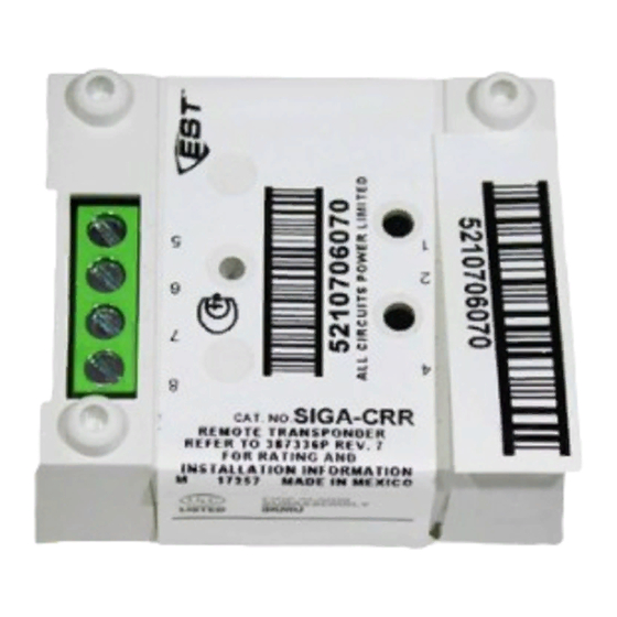
SIGA-CRR Polarity Reversal Relay Module
Installation Sheet
Description
The SIGA-CRR Polarity Reversal Relay Module is an
addressable device that is used to power and activate the
audible sounder in Signature audible detector bases.
The module can support a 2 A load of bases. Upon command
from the loop controller, the SIGA-CRR module relay transfers,
reversing the polarity of its 24 VDC output.
The module requires one address on the signaling line circuit
(SLC). Addresses are assigned electronically. There are no
address switches.
Diagnostic LEDs provide visible indication of the state of the
module through the cover plate:
•
Normal: Green LED flashes
•
Alarm/active: Red LED flashes
Personality code
The module requires the loop controller to download the
personality code that determines how the module operates.
Use the personality codes described below to configure the
SIGA-CRR. See Table 1 for listing information.
Signal - dry contact output. Configures
Personality code 8:
the module as a dry relay contact to control external
appliances (door closers, fans, dampers) or equipment
shutdown.
© 2012 UTC Fire & Security. All rights reserved.
Table 1: Personality code listing information
Code
Description
8
Signal - dry contact output Yes
Installation
Notes
•
The module is shipped from the factory as an assembled
unit; it contains no user-serviceable parts and should not
be disassembled.
•
This module does not operate without electrical power. As
fires frequently cause power interruption, discuss further
safeguards with the local fire protection specialist.
Install in accordance with all applicable local codes and
standards and the local authority having jurisdiction.
To install the module:
1.
Wire in accordance with "Wiring" on page 2.
2.
Write the address assigned to the module on the label
provided, and then apply the label to the module. Remove
the serial number label from the module, and then attach it
to the project documentation.
3.
Using the screw provided, mount the wall plate on the
module. See Figure 1 for mounting details.
4.
Using the screws provided, mount the wall plate (with the
module attached) on one of the compatible electrical
boxes listed in "Specifications" on page 3.
1 / 4
UL 864
CAN/ULC-
S527
Yes
P/N 387336P-EN • REV 6.0 • ISS 29FEB12
EN 54-18
Yes
Advertisement
Table of Contents

Subscribe to Our Youtube Channel
Related Manuals for EST SIGA-CRR


Summary of Contents for EST SIGA-CRR
- Page 1 The module can support a 2 A load of bases. Upon command from the loop controller, the SIGA-CRR module relay transfers, To install the module: reversing the polarity of its 24 VDC output.
- Page 2 Typical application connect to the terminal block of the module. Figure 3 shows a typical application. Here, each detector operates its sounder base. The SIGA-CRR is used to activate Notes all sounders, according to system programming rules. The CR •...
- Page 3 (1) Signaling line circuit (SLC) from previous device (2) SIGA-CR module (3) Auxiliary riser in (24 VDC from regulated power supply listed for fire protective signaling) (4) SIGA-CRR module (5) Riser monitor module or equivalent supervisory circuit Specifications Storage temperature range −4 to 140°F (−20 to 60°C)
- Page 4 Certification CPD certificates 0832-CPD-1018 2002/96/EC (WEEE directive): Products marked with this symbol cannot be disposed of as unsorted municipal waste in the European Union. For proper recycling, return this product to your local supplier upon the purchase of equivalent new equipment, or dispose of it at designated collection points.
Need help?
Do you have a question about the SIGA-CRR and is the answer not in the manual?
Questions and answers