Advertisement
Table of Contents
- 1 Description
- 2 Personality Codes
- 3 Installation
- 4 Personality Code Listing Information
- 5 To Install the Module
- 6 Protection from Transient Spikes
- 7 Wiring
- 8 To Install a Transient Protector
- 9 Two-Wire Smoke Detectors and Initiating Devices
- 10 Specifications
- 11 Regulatory Information
- 12 Contact Information
- 13 Personality Code Characteristics
- Download this manual
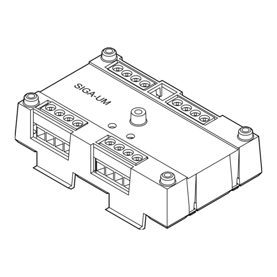
SIGA-UM Universal Class A/B Module
Installation Sheet
Description
The SIGA-UM Universal Class A/B Module is an addressable
module that you can configure to provide one of the following:
•
Two Class B dry contact initiating device circuits
•
One Class A dry contact initiating device circuit
•
One Class A or Class B notification appliance circuit
•
One Class A or Class B verified two-wire (conventional)
smoke detector circuit without dry contact initiating devices
on the same circuit
•
One Class A or Class B unverified two-wire (conventional)
smoke detector circuit with or without dry contact initiating
devices on the same circuit
•
One Form C dry contact relay output
The SIGA-UM requires two device addresses on the signaling
line circuit (SLC). Addresses are assigned electronically. There
are no addressing switches.
Diagnostic LEDs provide visible indication of the status of the
module:
•
Normal: Green LED flashes
•
Alarm/active: Red LED flashes
© 2016 Walter Kidde Portable Equipment, Inc.
Personality codes
Use the personality codes described below to configure the
SIGA-UM module. See Table 1 on page 2 for listing
information. See Table 2 on page 8 for personality code
electrical characteristics.
Alarm - NO latching (Class B). Factory
Personality code 1:
default. Configures input 1 or 2 for Class B, normally open dry
contact initiating devices (e.g., pull stations, heat detectors,
etc.). When the NO input contact of an initiating device is
closed, an alarm signal is sent to the loop controller and the
alarm condition is latched at the module.
2: Alarm - NO delayed latching (Class B).
Personality code
Same as code 1 except that contact closure must be
maintained for approximately 16 seconds before an alarm
signal is sent. This code is only for use with nonretarded
waterflow alarm switches.
3: Active - NO nonlatching (Class B).
Personality code
Contact closure causes an active instead of an alarm status
and does not latch at the module. Code 3 is typically used for
monitoring fans, dampers, and doors.
Active - NO latching (Class B). Contact
Personality code 4:
closure causes an active instead of an alarm status, which is
latched at the module. Code 4 is typically used for monitoring
supervisory and tamper switches.
Signal - dry contact output. Configures
Personality code 8:
the module as a Form C dry relay contact to control external
appliances (door closers, fans, dampers) or equipment
shutdown. Note: Jumper JP1 must be moved to pins 2 and 3
for dry contact operation.
Alarm - NO latching (Class A). Configures
Personality code 9:
the module for connection of Class A, normally open dry
contact initiating devices (e.g., pull stations, heat detectors,
etc.). When the NO input contact of an initiating device is
closed, an alarm signal is sent to the loop controller and the
alarm condition is latched at the module.
Personality Code 10:
Same as code 9 except that contact closure must be
maintained for approximately 16 seconds before an alarm
signal is sent. Code 10 is typically used with waterflow alarm
switches.
Personality code 11:
Same as code 9 except that contact closure causes an active
instead of an alarm status, and does not latch at the module.
Personality code 11 is typically used for monitoring fans,
dampers, and doors.
1 / 8
P/N P-047550-1726-EN • REV 08 • ISS 05AUG16
Alarm - NO delayed latching (Class A).
Active - NO nonlatching (Class A).
Advertisement
Table of Contents

Subscribe to Our Youtube Channel
Related Manuals for EST SIGA-UM


Summary of Contents for EST SIGA-UM
- Page 1 Installation Sheet Personality codes Use the personality codes described below to configure the SIGA-UM module. See Table 1 on page 2 for listing information. See Table 2 on page 8 for personality code electrical characteristics. Alarm - NO latching (Class B). Factory Personality code 1: default.
- Page 2 For personality codes 13, 14, 20 and 21 code 9 except that contact closure causes an active instead of First SIGA-UM on a loop to go into alarm will maintain the 2 an alarm status, which is latched at the module. Code 12 is wire detector circuit voltage and current so that the 2 wire typically used for monitoring supervisory and tamper switches.
- Page 3 (5) #4 × 1/2 self-tapping screw Two-wire smoke detector notes • A maximum of 15 SIGA-UM modules per circuit can be Protection from transient spikes configured to support two-wire smoke detectors (personality codes 13, 14, 20, and 21). However, if a...
- Page 4 • Polarity at terminals is shown in the supervisory condition. Connect as shown in the diagram. (Polarity reverses on alarm.) • IDC wiring is Style B (Class B) or Style D (Class A). To wire the module: Verify that all field wiring is free of opens, shorts, and ground faults.
- Page 5 Figure 4: Form C dry contact relay (personality code 8) (1)(2)(3) (1) SIGA-UM must be installed in the same room as the device it controls (2) Power-limited unless connected to a nonpower-limited source. If the source is nonpower-limited, eliminate the power-limited mark and maintain a minimum of 0.25 in.
- Page 6 Figure 6: Two-wire smoke detectors and initiating devices (personality codes 13, 14, 20, 21) (1) Class A two-wire smoke circuit (2) Maximum 12.5 Ω resistance per wire for Class A configurations (3) Class B two-wire smoke circuit (4) Not allowed with personality codes 14 and 21 (5) UL/ULC Listed 15 kΩ...
-
Page 7: Specifications
EOL-15 Contact information 22 kΩ EOL-22 47 kΩ EOL-47 For contact information, see www.est-fire.com. Circuit designation Signaling line circuit Class A, Style 6 or Class B, Style 4 Notification line circuit Class A, Style Z or Class B, Style Y... - Page 8 Table 2: Personality code characteristics Personality code Mode of operation Standby current Activated current EOL resistor 1, 2, 3, 4, 18 Class B initiating device circuit 458 µA 700 µA 47 kΩ Form C dry contact relay 127 µA 120 µA 9, 10, 11, 12 Class A initiating device circuit 307 µA...
Need help?
Do you have a question about the SIGA-UM and is the answer not in the manual?
Questions and answers