Sign In
Upload
Download
Table of Contents
Contents
Add to my manuals
Delete from my manuals
Share
URL of this page:
HTML Link:
Bookmark this page
Add
Manual will be automatically added to "My Manuals"
Print this page
×
Bookmark added
×
Added to my manuals
Manuals
Brands
KIPI Manuals
Heater
24 kW
Manual
KIPI 24 kW Manual
Hide thumbs
1
2
Table Of Contents
3
4
5
6
7
8
9
10
11
12
13
14
15
16
17
18
19
20
21
22
23
24
25
26
27
28
29
30
31
32
33
34
35
36
37
38
39
40
41
42
43
44
45
46
47
48
49
50
51
52
53
54
55
56
57
58
59
page
of
59
Go
/
59
Contents
Table of Contents
Bookmarks
Table of Contents
Table of Contents
1 General Information
2 Description and Purpose of the Device
3 Fuel Specification
4 Construction of the Heater
6 Safety Systems Used in the Heater
7 Transport
The Sequence of Assembly Works
9 Installation
Connecting the Heater to the Electrical System
Verification of the Ventilation System
10 Running
Preparing the Device for the First Start
The Sequence of Works Related to the First Start-Up
Safe Operation Conditions
Heater Maintenance
General Guidelines
Cleaning the Combustion Chamber
Cleaning the Hatch
Cleaning the Ash Pan
12 Technical Data
Models of Heaters, Overall Dimensions
Device Identification
Electrical Diagram of the Ecotouch 920P Regulator
Technical Parameters of Heaters
13 EC Declaration of Conformity
17 Attachments
Warranty - First Run - a Copy to be Sent Along with the GDPR Consent Clause
Warranty - First Start of the Heater
Warranty - Annual Inspection
Warranty - Two-Year Inspection
Repairs
Advertisement
Quick Links
Download this manual
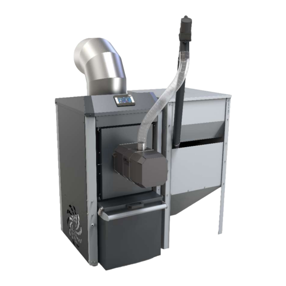
Name: KIPI air heater
24 kW,
30 kW,
50 kW,
70 kW,
BTI GUMKOWSKI Sp. z o.o. Sp.k.
ul. Obornicka 71, 62-002 Suchy Las
Manual
Models:
+48 61-811-70-37
biuro@kipi.pl
update 15-01- 2021
100 kW,
150 kW,
200 kW,
250 kW
1
Table of
Contents
Previous
Page
Next
Page
1
2
3
4
5
Advertisement
Table of Contents
Need help?
Do you have a question about the 24 kW and is the answer not in the manual?
Ask a question
Questions and answers
Related Manuals for KIPI 24 kW
Burner KIPI ROTARY 10 kW Instructions For Assembly And Use
(74 pages)
Heater KIPI 30 kW Manual
(59 pages)
Heater KIPI 70 kW Manual
(59 pages)
Heater KIPI 150 kW Manual
(59 pages)
This manual is also suitable for:
30 kw
50 kw
70 kw
100 kw
150 kw
200 kw
...
Show all
250 kw
Table of Contents
Print
Rename the bookmark
Delete bookmark?
Delete from my manuals?
Login
Sign In
OR
Sign in with Facebook
Sign in with Google
Upload manual
Upload from disk
Upload from URL


Need help?
Do you have a question about the 24 kW and is the answer not in the manual?
Questions and answers