
Related Manuals for MARS COMMERCE GSW2 PLUS 1000


Summary of Contents for MARS COMMERCE GSW2 PLUS 1000
- Page 1 GSW2 PLUS 1000 Advanced GSM/GPRS communication device INSTALLATION MANUAL Version: GSW2 PLUS 1000-Installation-Manual_V4_0-07072016.doc Valid from SW release “GSW_EF_PCK_20150817_v_3_2_6.hex”.
-
Page 2: Table Of Contents
GSW2 PLUS INSTALLATION MANUAL Contents INTRODUCTION ............................5 FEATURES AND APPLICATIONS ......................6 START UP ................................ 7 LED DISPLAY ..............................8 CLEAR ALL PROGRAMMED DATA FROM SIM ................... 9 CONNECTING DIAGRAM ......................... 10 PROGRAMMING GSW2 PLUS ........................11 THE GSW2 PLUS PARAMETERS ......................12 ALARM SUPPORT ................................ -
Page 3: Direct Access By Entering Access Code
GSW2 PLUS INSTALLATION MANUAL 9.20 RECEIVE SPIN ACCESS CODES PARAMETERS (PSPIN) ................... 38 9.21 RECEIVE INTERCOM BUTTON 1 PARAMATERS (PDEA) ..................39 9.22 RECEIVE INTERCOM BUTTON 2 PARAMATERS (PDEB) ..................39 9.23 STATE OF THE CREDIT FOR THE PREPAID CARD ....................39 9.24 STATE OF THE OUTPUTS (PORC) .......................... - Page 4 GSW2 PLUS INSTALLATION MANUAL FOR YOUR SAFETY Read these simple guidelines. Not following them may be dangerous or illegal. Read the complete user guide for further information. SWITCH ON SAFELY Do not switch the unit on when use of wireless phone is prohibited or when it may cause interference or danger.
-
Page 5: Introduction
GSW2 PLUS INSTALLATION MANUAL INTRODUCTION GSW2 PLUS is a universal remote controller based on GSM technology. It is designed as unlimited range, wire free, low cost, and highly robust remote control system. With GSW2 PLUS and the external voice module it is also possible to build an intercom application for security sensitive installations. -
Page 6: Features And Applications
GSW2 PLUS INSTALLATION MANUAL FEATURES AND APPLICATIONS Features: Built-in 4 band GSM module Up-to 2 buttons call support (option) Up-to 2 alarm inputs 2 outputs (relay supported) Up to 1000 telephone numbers for Caller ID (CLIP) support ... -
Page 7: Start Up
GSW2 PLUS INSTALLATION MANUAL START UP VERY USE A MICRO SIM CARD (micro-SIM, see the picture) IMPORTANT WITH MEMORY FOR UP TO 250 CONTACTS! Insert SIM card to be used for GSW2 PLUS in your personal mobile phone. ERASE THE PIN CODE! IMPORTANT ... -
Page 8: Led Display
GSW2 PLUS INSTALLATION MANUAL LED DISPLAY Blue LED (LED1) Indicates the level of the GSM signal from 1 to 5 LED flashes (1 is weak signal, 5 is excellent signal) Red LED (LED2) LED 2 is used to indicate ongoing traffic on the GSM interface. Yellow LED (LED3) Short flashing indicates that the GSM module is ON, but it is not yet connected on the GSM network. -
Page 9: Clear All Programmed Data From Sim
GSW2 PLUS INSTALLATION MANUAL CLEAR ALL PROGRAMMED DATA FROM SIM This is highly recommended when a SIM card you are going to use for the GSW2 PLUS is not new and it already has some data stored in the phone book memory. By sending this SMS to GSW2 PLUS all programmed parameters and numbers are cleared: ;SDCLR;... -
Page 10: Connecting Diagram
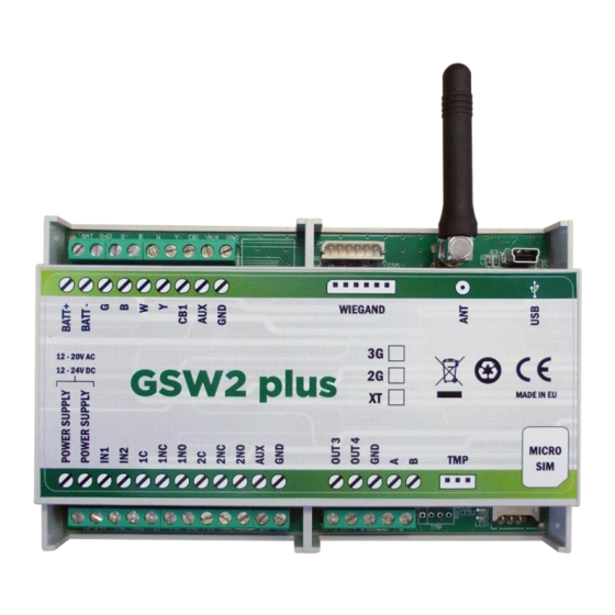
GSW2 PLUS INSTALLATION MANUAL CONNECTING DIAGRAM Before connection the GSW2 PLUS device please take a look at connection diagram. POWER OUT 3 Wiegand output DOUT 1 Power supply – 12,0 -20,0V AC or SUPPLY 12,0 – 24,0V DC OUT 4 Wiegand output DOUT 0 Alarm input 1 Ground... -
Page 11: Programming Gsw2 Plus
GSW2 PLUS INSTALLATION MANUAL PROGRAMMING GSW2 PLUS GSW2 PLUS device supports different types of programming: You can program GSW2 PLUS remotely by SMS command. You can program GSW2 PLUS directly with the use of USB connection on the device. Please contact your reseller to receive the application running on PC for management of the GSW2 PLUS and the appropriate USB drivers. -
Page 12: The Gsw2 Plus Parameters
GSW2 PLUS INSTALLATION MANUAL THE GSW2 PLUS PARAMETERS To support versatile functionality of GSW2 PLUS different parameters are used. The parameters are divided in logical sections and are described in the following chapters. 8.1 ALARM SUPPORT Alarm reporting is supported by group of different parameters. First section is used to define the relations needed for alarm to be trigged. -
Page 13: Table 1: In, Id And Dd Parameters
GSW2 PLUS INSTALLATION MANUAL 8.1.1.2 ID parameters ID parameter determines time period of the pulse length to trigger the alarm. The pulse time can be from 0,5 seconds to 9999 seconds. The default time is 0,5 seconds when the parameter value is 0. Parameter is in seconds. -
Page 14: Table 3: Remote Alarm Reporting Parameters
GSW2 PLUS INSTALLATION MANUAL 8.1.2 REMOTE REPORTING ALARM EVENTS Parameters used to define the way to report the alarm event. GSW2 PLUS device send SMS messages for reporting alarm events. NOTE 8.1.2.1 TN parameters Telephone numbers for remote alarm reporting are listed as TN parameters. Remote alarm reporting on GSW2 PLUS is done via SMS messages. -
Page 15: Table 4: Remote Alarm Reporting Parameters Example
GSW2 PLUS INSTALLATION MANUAL Example: Direct programming on the SIM card GSW2 PLUS PROGRAMMING TABLE Name Number Description 042376678 1st telephone number Input 1 reports alarm to TN1 & TN3 1234 Input 2 reports alarm to TN1 & TN2 & TN3 & TN4 NAC event sent to TN1 Table 4: Remote alarm reporting parameters example ... -
Page 16: Output Management
GSW2 PLUS INSTALLATION MANUAL 8.2 OUTPUT MANAGEMENT GSW2 PLUS supports the possibility to report alarms from inputs and any other events locally via 2 outputs. The behavior is defined using next parameters 8.2.1 OS parameters GSW2 PLUS device has 2 dedicated relay supported outputs. Outputs can be configured to different behavior: ... -
Page 17: Table 5: Output Management Parameters
GSW2 PLUS INSTALLATION MANUAL Time control is used in next functions: CLIP NOTE DTMF Input alarms ( OD parameters ) 8.2.5 Table of parameters Name Comment Mode of operation for output 1 Mode of operation for output 2 Input 1 direct link to outputs Input 2 direct link to outputs GSM network problem direct link to outputs NAC direct link to outputs... -
Page 18: Security Level - Sl
GSW2 PLUS INSTALLATION MANUAL 8.3 SECURITY LEVEL - SL SL parameter from 0 to 5 defines which telephone number stored in the phone book from TN1 – TN5 can enter into programming and remote control of the GSW2 PLUS (dialing the GSW2 PLUS phone number or sending the SMS). -
Page 19: Prepaid Card Credit And Validity Information
GSW2 PLUS INSTALLATION MANUAL 8.4 PREPAID CARD CREDIT AND VALIDITY INFORMATION GSW2 PLUS can be used with prepaid SIM cards and its limitations. To be able to overcome this limitation of the prepaid SIM cards, GSW2 PLUS offers the possibility of automatic checking mechanism for credit and time expiration. -
Page 20: Table 9: Prepaid Card Validity Parameters
GSW2 PLUS INSTALLATION MANUAL 8.4.1.3 CREF, CTIM, CVODA parameters Parameters are used to find the credit value of the prepaid SIM card. Strings under these parameters are used to pars the replay message from the GSM provider. CREF - Pars string for the replays received from CC1 number ... -
Page 21: Set-Up Parameters
GSW2 PLUS INSTALLATION MANUAL 8.5 SET-UP PARAMETERS Different parameters are used to support versatile functionality of GSW2 PLUS. 8.5.1 WMOD parameter Parameter is used to define mode of operation of the inputs (alarm or intercom mode). If the input number is not stated in the WMOD parameter then this input is in alarm mode, else it is in intercom mode. - Page 22 GSW2 PLUS INSTALLATION MANUAL 8.5.6 TSTT parameter TSTT parameter is used to define reference point for sending test message. If this parameter is set than after restart of the GSW2 PLUS first test SMS will be send out at time defined with TSTT parameter.
- Page 23 GSW2 PLUS INSTALLATION MANUAL 8.5.12 ADF parameter Parameter is used to define voice refresh function, to prevent blocking of SIM in some GSM networks. NOTE If this function is enabled GSW2 PLUS device will make voice call to TN1 number. 8.5.13 LNG parameter LNG parameter switches between the pre-programmed languages:...
-
Page 24: Table 11: Set-Up Parameters
GSW2 PLUS INSTALLATION MANUAL 8.5.17 Table of parameters Name Comment WMOD Mode of operation of inputs Tel. number of GSW2 PLUS device Auto answer ring number Hidden telephone number SMS test time out TSTT Periodic test SMS start time Manual GSM provider selection Microphone volume control Speaker volume control ARST... -
Page 25: Sms Messages Editor
GSW2 PLUS INSTALLATION MANUAL 8.6 SMS MESSAGES EDITOR You can write and send a short SMS message for each alarm input. The default message is English, but it is possible to change language with LNG parameter. Each message is built from 3 parts and user can write the first (User Location) and the second (alarm event) part of the message. -
Page 26: Intercom
GSW2 PLUS INSTALLATION MANUAL 8.7 INTERCOM Intercom functionality is supported by a set of parameters, used to tweak the functionality to each user needs. To support intercom function on particular input set WMOD parameter to appropriate value (by default WMOD parameter is set to 0): NOTE To use IN1 (CB1) as a call button 1 send SMS to GSW2 PLUS: ;+WMOD=1;... - Page 27 GSW2 PLUS INSTALLATION MANUAL 8.7.3 Intercom call groups For each button GSW2 PLUS incorporates a group of parameters. There are 2 groups of parameters. 8.7.3.1 xTN1 to xTN5 parameters Parameters are the call numbers for intercom application. 8.7.3.2 RTNx parameter Parameter defines the ring time time-out.
-
Page 28: Table 15: Intercom Parameters
GSW2 PLUS INSTALLATION MANUAL 8.7.4 Table of parameters Name Comment Time out for voice connection. Input used as cancle button ATN1 Button 1, Telephone number 1. ATN2 Button 1, Telephone number 2. ATN3 Button 1, Telephone number 3. ATN4 Button 1, Telephone number 4. ATN5 Button 1, Telephone number 5. -
Page 29: Controling Outputs With Dtmf
GSW2 PLUS INSTALLATION MANUAL Figure 5: GSW2 PLUS Intercom connection diagram - details 8.8 CONTROLING OUTPUTS WITH DTMF GSW2 PLUS can control the outputs with the use of DTMF. This is very useful function in the intercom application. To control the outputs the user must press the combination of 2 digits. First digit is used to select the output (1 to 2), the second digit is used to activate (1) or deactivate (0) the output. -
Page 30: Clip - Caller Id
GSW2 PLUS INSTALLATION MANUAL GSW2 PLUS must be in voice connection to support DTMF output control! NOTE Example: DTMF combination Description Deactivate ALL outputs Activate ALL outputs Activate output 1 Deactivate output 2 Table 17: DTMF control example 8.9 CLIP – CALLER ID CLIP is used to provide the “free of charge”... -
Page 31: Wiegand Interface
GSW2 PLUS INSTALLATION MANUAL CLP1 … CLP1000 parameter 8.9.6 Set of telephone number, which can control the output. The number not on CLP list is not able to control the output using clip functionality. 8.9.7 Table of parameters Name Comment CLPEN Enable CLIP functionality CLPOU... -
Page 32: Rd Party Wiegand Device)
GSW2 PLUS INSTALLATION MANUAL 8.11 DIRECT ACCESS BY ENTERING ACCESS CODE (VIA WIEGAND CONNECTOR FROM 3 PARTY WIEGAND DEVICE) The user may control the predefined outputs by entering the PIN access codes. PIN access code from 1 to 500 (PIN1 to PIN500) will activate Output 1, PIN access codes from 501 to 1000 (PIN501 to PIN1000) will activate Output 2. -
Page 33: Event Loging
GSW2 PLUS INSTALLATION MANUAL SPIN access code from SPIN1 to SPIN50 will activate the relay output. NOTE Set the SPIN access entry codes active output first (disabled by default). ;SPINO=1; 8.12.1 SPIN1 to SPIN50 SPINx parameters are the temporary SPIN access codes for controlling the relay output. SPINCx parameters are the determination, how many times SPINx code can be used. -
Page 34: Special Sms Commands
GSW2 PLUS INSTALLATION MANUAL 8.13.1 LOGN parameter Parameter is used for defining the number of events printed out on PLOG request. 8.13.2 LOGI parameter LOGI parameter is used to enable and define GSW2 PLUS log storage. LOGI=0 Logging is OFF LOGI=1 Logging in internal memory LOGI=2... -
Page 35: Table 26: Sms Commands
GSW2 PLUS INSTALLATION MANUAL 8.14.2 SDCLR command To clear all data on SIM card SDCLR command is used. 8.14.3 LCRL command Command clears log on GSW2 PLUS device. 8.14.4 CLPCLR command Command is used to delete all CLP numbers. 8.14.5 MRES command Command is used to manually restart GSM module on GSW2 PLUS device. -
Page 36: Print-Out Of The Parameters
GSW2 PLUS INSTALLATION MANUAL PRINT-OUT OF THE PARAMETERS The user can check the settings of ALL parameters on the GSW2 PLUS. 9.1 RECEIVE ALL PARAMETERS (PALL) By sending this command to GSW2 PLUS you receive SMS messages with all parameters that are currently programmed in the unit: ;PALL;... -
Page 37: Receive Input Filter Value (Pid)
GSW2 PLUS INSTALLATION MANUAL 9.8 RECEIVE INPUT FILTER VALUE (PID) By sending this command to GSW2 PLUS you receive SMS message with all currently programmed Input filters (ID1 – ID2): ;PID; 9.9 RECEIVE OUTPUT FILTER VALUE (POD) By sending this command to GSW2 PLUS you receive SMS message with all currently programmed direct output links (OD1 –... -
Page 38: Receive Credit Pars Parameters (Pcref)
GSW2 PLUS INSTALLATION MANUAL 9.16 RECEIVE CREDIT PARS PARAMETERS (PCREF) By sending this command to GSW2 PLUS you receive SMS message with all currently programmed credit parse parameters (CREF, CVODA…): ;PCREF; 9.17 RECEIVE CREDIT CHECK TELEPHONE NUMBERS (PCN) By sending this command to GSW2 PLUS you receive SMS message with programmed numbers for credit checking (CC1, CC2…): ;PCN;... -
Page 39: Receive Intercom Button 1 Paramaters (Pdea)
GSW2 PLUS INSTALLATION MANUAL 9.21 RECEIVE INTERCOM BUTTON 1 PARAMATERS (PDEA) By sending this command to GSW2 PLUS you receive SMS message with all currently programmed button 1 group parameters (ATN1, ATN2, ATN3, ATN4, ATN5, RTNA, SDNA, SDDA, TZSA, TZEA): ;PDEA;... -
Page 40: Changing Parameters Using The Sms Command
GSW2 PLUS INSTALLATION MANUAL 10 CHANGING PARAMETERS USING THE SMS COMMAND All programming parameters for GSW2 PLUS can also be sent by SMS command. Each SMS command should start and stop with semicolon. If the confirmation SMS is needed, put “+” at the beginning of the command SMS. -
Page 41: Default Settings On Gsw2 Plus
GSW2 PLUS INSTALLATION MANUAL 11 DEFAULT SETTINGS ON GSW2 PLUS GSW2 PLUS PROGRAMMING TABLE Name Default Value Short Description Telephone number 1 Empty Telephone number 2 Empty Empty Telephone number 3 Empty Telephone number 4 Empty Telephone number 5 Input 1 control Input 2 control Output 1 mode Output 2 mode... - Page 42 GSW2 PLUS INSTALLATION MANUAL GSW2 PLUS PROGRAMMING TABLE Name Default Value Short Description Speaker volume setting ( 0 - 20 ) Low credit value Language selection Connection time out value LOGN Number of log events for printing out LOGI Log interface Automatic log clear Auto dial ARST...
-
Page 43: Table 28: Gsw2 Plus Default Settings
GSW2 PLUS INSTALLATION MANUAL GSW2 PLUS PROGRAMMING TABLE Name Default Value Short Description BTN4 Empty Grope B, telephone number 4 BTN5 Empty Grope B, telephone number 5 RTNB Ring time SDNB Self dial number SDDB Self dial delay TZSB Time zone start TZEB Time zone end Wiegand mode of operation... -
Page 44: Parameters Print-Out Commands
GSW2 PLUS INSTALLATION MANUAL 12 PARAMETERS PRINT-OUT COMMANDS GSW2 PLUS PRINT TABLE Name Short Description Prints all parameters available on GSW2 PLUS. PALL Prints SW version of GSW2 PLUS. Prints GSM network signal quality of GSW2 PLUS. Prints TNx numbers. Prints LNx links. -
Page 45: Technical Specifications
GSW2 PLUS INSTALLATION MANUAL 13 TECHNICAL SPECIFICATIONS Description Value 12,0 - 20,0V AC or Power Supply 12,0 – 24,0V DC Current consumption - peak Current consumption - transmitting mode 250mA Current consumption - idle mode 40mA Quad band GSM module 850/900/1800/1900 MHz 126 ×... -
Page 46: Contacts
GSW2 PLUS INSTALLATION MANUAL 14 CONTACTS MARS COMMERCE d.o.o. MIRKA VADNOVA 19 SI-4000 KRANJ SLOVENIA WEB SITE: www.mars-commerce.com SALES: TEL: +386 4 280 74 06 E-MAIL: sales@mars-commerce.com TECHNICAL SUPPORT: E-MAIL: tomaz@mars-commerce.com Page 46...
Need help?
Do you have a question about the GSW2 PLUS 1000 and is the answer not in the manual?
Questions and answers