Advertisement
Installation manual
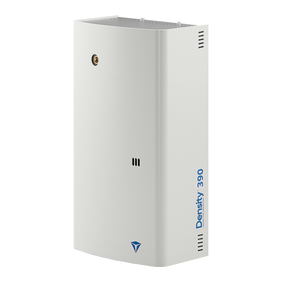
DENSITY 390 - 900 - 1500 - 2400
Density fog generator range 390 – 900 – 1500 – 2400, is based
on the same mechanical platform. The physical size is the same
for the 4 units, but the central heat exchange part, is different
in size, and thereby the machines are different in generated fog
volume, covering places from tiny rooms, up to large warehouses.
Version 1.1.4
www.densityglobal.com | help@densityglobal.com
Advertisement
Table of Contents

Related Manuals for DENSITY DENSITY 390

Summary of Contents for DENSITY DENSITY 390
- Page 1 Installation manual DENSITY 390 - 900 - 1500 - 2400 Density fog generator range 390 – 900 – 1500 – 2400, is based on the same mechanical platform. The physical size is the same for the 4 units, but the central heat exchange part, is different in size, and thereby the machines are different in generated fog volume, covering places from tiny rooms, up to large warehouses.
- Page 2 Shooting time setting How to set the shooting time Shooting table for the 4 models Fog fluid system The Density fog refill How to connect the fog refill Where to place the fog refill Reset the fluid measuring system Front LED’s Description of the 3 front LED’s...
-
Page 3: Prepare For Installation
6. IP/LAN connection. 7. IP/LAN card. 8. Connection for control. Watch a video 9. Connection for relay output. showing how to open 10. Reset button. the Density fog 11. Main power connection. generator. Version 1.1.4 page 3/20 www.densityglobal.com | help@densityglobal.com... - Page 4 Holes for installation. Dimensions for holes. « Keyhole » for installation. Mount screws on the wall. Watch a video showing how to install the Density fog generator. Hang unit using « Keyhole ». Version 1.1.4 page 4/20 www.densityglobal.com | help@densityglobal.com...
-
Page 5: Nozzle Adjustment
3. Wiring Signal cables and IP/LAN cable to inserted on top of the machine. Use cable relief to fasten the cables. Live, Neutral, and Earth to be connected as shown. Mains cables to be inserted in the bottom plate of the machine. Use cable relief to fasten the cable. -
Page 6: Backup Battery
5. Backup battery Insert 2 long cable ties as pictured. Insert battery* in the cable ties and tighten. Tighten the ties and cut the end part. Connect the battery*, red to red, black to black. *We recommend to use Fiamm 12V 2Ah battery type FG20201 Vds or equivalent (BAREN type, for example). Watch a video showing how to insert and connect... -
Page 7: Input Signal
6. Input signal The Density fog generator has 4 +1 inputs to control the fog operation. 4 inputs are galvanically isolated optocoupler inputs. They are normally triggered by 12VDC applied. You can choose if the inputs shall be activated by NO or NC logic (Normal Open or Normal Closed), meaning that you can choose to activate the inputs, by 12VDC Removal or by 12VDC Applied. - Page 8 6.1. Connection diagram examples ACTION DAYTIME ACTION NIGHTTIME ACTION ALARM COM 1 COM 2 COM 3 + 12V + 12V + 12V + 12V PRIMARY TRIG ARM + ARM - TRG + PRIMARY TRIG PRIMARY TRIG TRG - IN 0 + INTRUDER SYSTEM DISARMED INTRUDER SYSTEM ARMED INTRUDER SYSTEM IN ALARM...
- Page 9 6.2.1 Connection diagram examples (VERIFICATION SENSOR) ACTION DAYTIME ACTION NIGHTTIME ACTION ALARM ACTION ALARM + VERIFICATION COM 1 COM 2 COM 3 + 12V + 12V + 12V + 12V + 12V ARM + ARM - TRG + TRG - PRIMARY TRIG PRIMARY TRIG ALARM TRIG...
- Page 10 6.2.2 Connection diagram examples (SECONDARY PIR SENSOR) ACTION DAYTIME ACTION NIGHTTIME ACTION ALARM ACTION ALARM + VERIFICATION COM 1 COM 2 COM 3 + 12V + 12V + 12V + 12V + 12V ARM + ARM - TRG + TRG - PRIMARY TRIG PRIMARY TRIG PRIMARY TRIG...
- Page 11 6.3. Connection diagram examples (PANIC FUNCTION) ACTION DAYTIME ACTION NIGHTTIME ACTION ALARM ACTION ALARM + VERIFICATION COM 1 COM 2 COM 3 + 12V + 12V + 12V + 12V + 12V ARM + ARM - TRG + TRG - PRIMARY TRIG PRIMARY TRIG PRIMARY TRIG...
- Page 12 6.4. Connection diagram examples (ACTIVE TRIG, NC – NORMAL CLOSED) ACTION DAYTIME ACTION NIGHTTIME ACTION ALARM ACTION ALARM + VERIFICATION COM 1 COM 2 COM 3 + 12V + 12V + 12V + 12V + 12V ARM + ARM - TRG + TRG - PRIMARY TRIG...
-
Page 13: Output Signal
7. Output signal The fog machine has 5 RELAY YOU CAN CHANGE outputs. EMPC THE POSITION OF THE JUMPER EMP = Empty fog refill TO CHOOSE BETWEEN FLT = Fault NO OR NC FUNCTION TMP = Tamper switch open FLTC FVL = SHOOT verification AUX = For future use TMPC... -
Page 14: Dip Switch
8. Dipswitch On the PCB, you will find a 8-pol DIPSWITCH row: FIRETIME The function of these 8 DIPSWITCHES: SW 1 = ON = SHOOT verification relay active RESET SW 2 = ON = Front LED’s are OFF SW 3 = ON = Internal Buzzer turned OFF SW 4 = ON = All output relay in Active Security (*) SW 5 = ON = PANIC function enabled BOOT... - Page 15 9.1. How to program fog shooting time Count the number of PUSH and HOLD flashes on the LED’s “FIRETIME” button. FIRETIME (The BEEPER will also Count the number of beep synchronously with flashes on the LED’s the LED’s). RESET (The BEEPER will also beep synchronously with the LED’s).
- Page 16 10.1. RESET fluid measure system IMPORTANT! When inserting a new fog refill, or when exchanging a FIRETIME Density fog refill, you need to RESET the fluid measuring system. RESET Simply push and hold the RESET button for 3-4 seconds. See how BOOT to reset the fluid.
- Page 17 Green LED HEATING When on: the machine is hot and ready for the fog emission. When flashing: the heating process is in progress. In this step, the Density machine is heating but is not ready to shoot. Blue LED When on: the machine is armed and, if hot, it’s ready to shoot.
-
Page 18: Product Information
13. Final test – Delivering the product to the owner CHECKLIST for finalizing the installation: 1. Check all signals from the Intruder Alarm system, according to the selected diagram. 2. Has the NOZZLE been adjusted to the best position? 3. Make a full TEST SHOOTING at the installation site, to ensure that the dimensioning is OK. 4. - Page 19 9. Before testing the unit, remember to report it in advance to the firefighters in your area to avoid false alarms. 10. Remember to put provided warning and deterrent labels about the presence of Density on the front and back door windows.
- Page 20 22. The tip of a stranded conductor should not be soft-soldered where the conductor is subjected to contact pressure. 23. The Density unit machine should not be exposed to water spray or dripping. 24. Request to Density group or its distributors to take part in courses for installers to ensure the optimal Version 1.1.4 page 20/20...
Need help?
Do you have a question about the DENSITY 390 and is the answer not in the manual?
Questions and answers