Table of Contents
Advertisement
Quick Links
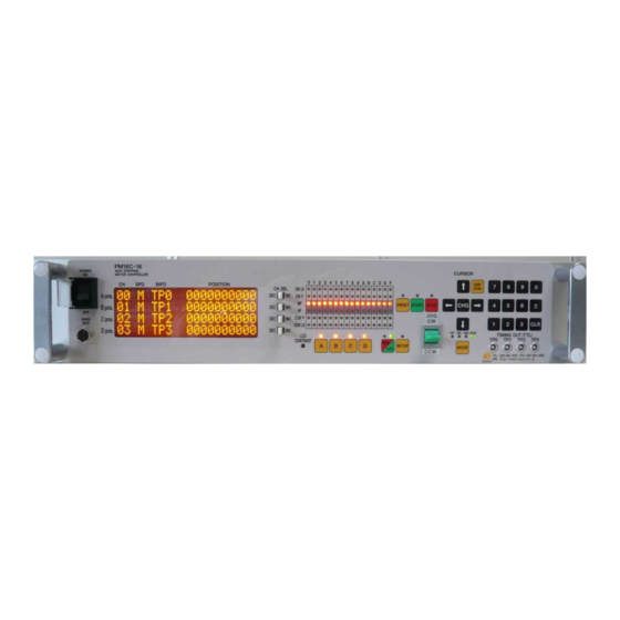
16ch STEPPING MOTOR CONTROLLER
PM16C-16
USER'S MANUAL
No. 3288(rev.2)
APPLICATION OF ELECTRONIC DEVICES
TSUJI ELECTRONIC CO. Ltd.
3739 Kandatsu-machi Tsuchiura-city
Ibaraki-Pre 300-0013 JAPAN
PHONE.+81-(0)29-832-3031 FAX. +81-(0)29-832-2662
URL
http://www.tsujicon.jp/
E-mail info2@tsuji-denshi.co.jp
Advertisement
Table of Contents

Related Manuals for TSUJI ELECTRONICS PM16C-16

Summary of Contents for TSUJI ELECTRONICS PM16C-16
- Page 1 16ch STEPPING MOTOR CONTROLLER PM16C-16 USER’S MANUAL No. 3288(rev.2) APPLICATION OF ELECTRONIC DEVICES TSUJI ELECTRONIC CO. Ltd. 3739 Kandatsu-machi Tsuchiura-city Ibaraki-Pre 300-0013 JAPAN PHONE.+81-(0)29-832-3031 FAX. +81-(0)29-832-2662 http://www.tsujicon.jp/ E-mail info2@tsuji-denshi.co.jp...
-
Page 2: Table Of Contents
CONTENTS CONTENTS CONTENTS ......................1 1 Abstract ........................ 4 1-1 Introduction ....................4 1-2 Architecture ....................5 1-3 Connection Diagram ..................5 2 Parts names and function ..................6 2-1 Front Panel ....................6 MOTOR STATUS LED................... 7 2-2 Rear Panel ....................8 Pulse out Dub connector (PULSE) Pin assignment ........ - Page 3 CONTENTS 5-10 Page10 LAN setting ................... 27 5-11 Page11: Program version change, return time from mode set screen, and LCD brightness adjustment ................27 6 Operation of Motor ....................28 6-1 Local mode operation .................. 28 6-2 Remote/Local switching command .............. 28 6-3 Command to read out of motor status............
- Page 4 CONTENTS 12-2 Command List ................... 65 13 Revision History ....................67 14 Performance and Specifications ............... 68...
-
Page 5: Abstract
16 motors at the same time by remote operation. An operation system is almost the same as PM16C-04XDL. The difference with PM16C-04XDL is described below. 1. PM16C-16 controls 16 motors at the same time by LAN, RS-232C, and GP-IB communication. 2. The command which reads the state of all channel was added. -
Page 6: Architecture
× 16ch LAN RS-232C GP-IB 1-3 Connection Diagram LS Cable (Dsub 9pin) Sensor Pulse Cable (Dsub 9pin) Pulse Driver Motor PM16C-16 Up to 16 set connectable. LAN Cable RS-232C Cable GP-IB Cable Sensor Pulse Driver Motor... -
Page 7: Parts Names And Function
FAX:029-832-2662 URL htt p://www. tsujicon. jp 11 12 Name Function POWER switch This is the power switch of PM16C-16. Connect the Hand Box here (option). Hand Box connector See 17 page. 20 character and 4 line LCD. LCD display Motor drive status and each channel data are displayed here. -
Page 8: Motor Status Led
2 Parts names and function Name Function Starts CW or CCW JOG operation. Motor drives just JOG set pulse with one push. If you hold over JOG switch 0.4 sec., motor drives while holding. In SETUP mode, changes the page of setup function. Select the drive mode when pushing start button. -
Page 9: Rear Panel
2 Parts names and function 2-2 Rear Panel CH0 CH1 CH2 CH3 CH4 CH5 CH6 CH7 PUL SE PUL SE PUL SE PUL SE PUL SE PUL SE PUL SE PUL SE GP- IB RS-232 C F3A LAN LS IN LS ... -
Page 10: Limit Switch Input Dsub Connector(Ls In) Pin Assignment
37.6mm. DE-C1-J6 (JAE), XM2S-0911 (OMRON), HDE-CTF (HIROSE) etc. are recommended connectors. RS-232C connector The pin assignment of Dsub 9pin connector at PM16C-16 Function Pin No. side is shown right. Use cross cable between PM16C-16 and - your PC. - - -... -
Page 11: Preparation Of A Communication Line
3 Preparation of a communication line 3 Preparation of a communication line 3-1 The outline of communication control PM16C-16 is be equipped communication control by LAN, RS-232C, and GP-IB. Initial setting is required of each communication. Any initial setting can be performed in SETUP mode. -
Page 12: The Outline Of Motor Control
4 The outline of motor control 4-1 Remote mode and Local mode PM16C-16 have two ways of control mode, remote mode and local mode. In local mode, PM16C-16 controls motor with switches attached front panel and hand box. Commands from communication line which drives motor and overwrite the motor setting are invalid, but which reads the data are available. -
Page 13: Constant Drive (Const)
4 The outline of motor control Constant drive (Const) Speed MAX SPEED (= HSPD/MSPD/LSPD) Time start command stop command Motor drives at MAX speed as soon as drive execution, and stops immediately as soon as stop operation. Too fast drive speed causes motor step out. Low speed drive is always constant drive at all drive mode. -
Page 14: Control Screen
4 The outline of motor control Although it is fundamentally the same as trapezoidal form acceleration drive, the velocity change at the time of acceleration and deceleration start and the time of acceleration and deceleration stop is performed according to S shaped form approximated to the parabola. -
Page 15: Mode Setup Screen
4 The outline of motor control Data Function The display of from which port a timing signal is outputted. In V1.01 or later, “---” is displayed when the output port is not assigned to all the port. You can select display data at this area with “CHG”... -
Page 16: Home Position Set And Search Drive
4 The outline of motor control 4-5 Home Position Set and Search drive Home position of the unit is set by home position search drive. If the sensor of the origin point (H.P switch) is detected, motor will stop automatically and the moving direction and the origin point at the time of detection are memorized on a main unit. - Page 17 4 The outline of motor control When you set H.P to direction CW, you have to set motor position to CCW side against origin sensor, then move motor from CCW to CW side by operation switch JOG CW or START + JOG CW. Once detect the origin point, motor stopped suddenly, origin point procedures finished.
-
Page 18: Hand Box (Optional)
4 The outline of motor control completely, and it goes to the origin point by LSPD. Motor stopped suddenly, if the origin point sensor is detected from a direction opposite to the direction which started detection of the origin point. Then the position of pulse data is memorized and the direction approaching a sensor is also memorized. -
Page 19: 04Type Hand Box Controller (Pm16-Hdx 4 Axis Control)
3. CH B JOG switch It is the same function as the JOG switch of the front pannel of PM16C-16, and it operates the channel B which is displayed on LCD display. When you press once, it gives the instruction once in the direction (CW or CCW) in... -
Page 20: 16Type Hand Box Controller(Pm16-Hdx16 16 Axis Selected Control
4 The outline of motor control 16TYPE Hand box controller(PM16-HDX16 16 axis selected control) Control a channel that is selected from 16 channels. 1. Channel indicated LED It displays the channel that is controlled, and it displays a channel as Hexadecimal number (0 ~ F). 2. -
Page 21: Setup Mode
5 SETUP MODE 5 SETUP MODE All channel motor initial data and communication line setting operation is available at this mode. Push SETUP button at Local mode, LOCAL drive mode and SETUP mode are exchanged. SETUP mode contains 11 pages. You can increment the page with clicking JOG switch to CW, and decrement to CCW. -
Page 22: Digital Limit Switch Setting
5 SETUP MODE Set independently CW / CCW the contact logic of the limit switch. The right "_" will change to "□" When the limit switch is active. N.O: Select when using the limit switch normally open (A contact). N.C: Select when using the limit switch normally close (B contact). -
Page 23: Speed Setting
5 SETUP MODE 5-3 Page3 Speed setting C H : 0 0 S P E E D ( p p s ) H : 5 0 0 0 0 0 0 M : 5 0 0 0 0 0 0 J O G : 0 0 0 1 L : 5 0 0 0 0 0 0... -
Page 24: Rel/Abs/Scan Preset Data Setting
5 SETUP MODE : Selection of stop mode: In case of limit switch SLOW/FAST default: SLOW Select from the FAST (Sudden stop) or SLOW (Deceleration stop) how to stop when it detects a limit switch. : Selection of stop mode: In case of push button. (Panel operation) SLOW/FAST default: SLOW Select from FAST (Sudden stop) or SLOW (Deceleration stop) how to stop when you push the STOP button in local mode. -
Page 25: Home Position Setting
5 SETUP MODE 5-6 Page6 Home position setting C H : 0 0 H P L S : E N A N O _ P 6 O R G . S T A R T : C C W M ( C C W ) O F F S E T . -
Page 26: Timing Out Setting
5 SETUP MODE 5-7 Page7 TIMING OUT setting For more information about the TIMING OUT signal, see page 47. C H : 0 0 T . O U T : P . 1 m s S T A R T - 0 1 2 3 4 5 6 7 8 9 S T O P - 0 1 2 3 4 5 6 7 8 9... -
Page 27: Timing Out Channel Setting
5 SETUP MODE 5-8 Page8 TIMING OUT channel setting It displays which channels are assigned to TIMING OUT four output ports From software version 1.01, channel fixed mode of the output port has been added. You can use TIMING OUT output of the specified channel, regardless of the display. T I M I N G T P 0 : C H 0 0 O U T... -
Page 28: Lan Setting
: MAC address It's MAC address inside LAN module. : IP address Initial value:192.168.1.55 Set the IP address of PM16C-16 with the cursor keys and a numeric keypad. :PORT number Initial vaule:7777 Set the PORT number of PM16C-16 with numeric keypad. -
Page 29: Operation Of Motor
6 Operation of Motor 6 Operation of Motor Here, you will move the motor actually. Prior to actually drive, complete the following settings. ・Connecting to an external device driver, limit switches, etc. (Page 8) ・Configuring the driving speed. (Page 22) ・Configuring the amount of movement (only the absolute value and relative value movement) (Page 13) Operate the motor, after the setup is complete. -
Page 30: Command To Read Out Of Motor Status
6 Operation of Motor 6-3 Command to read out of motor status <ch>: 0 ~ F(Hexadecimal) for channel. Command STS? Read motor status which is displayed on LCD. <RL><0123>/<DIR>/<LS>/<MT>/<POS>/<POS>/<POS>/<POS> R/ REMOTE control mode <RL> L/ LOCAL control mode Show displayed motor CH No. at 1 digit hex. The order of this <0123>... -
Page 31: Limit Switch(Ls) Status Read Command
The data is in order from CH0 to CHF. STS_16? Reply: Example SSSSPSSSSSSNSSSS/00000080030000000000000300000000 Remarks New command at PM16C-16. Limit switch(LS) status read command Command LS? Read displayed 4 CH motor on LCD LS status. <0123><LS> Show displayed motor CH No. at 1 digit hex. The order of this <0123>... -
Page 32: Commands For Current Positon Read Or Set
CW LS The data is in order from CH0 to CHF. Example LS_16? Reply: 888B888888888888 Remarks New command at PM16C-16. Commands for current positon read or set Command PS? <ch> Read current position of specified motor. Specify in the Hexadecimal number 0~F to read out the Argument <ch>... -
Page 33: Motor Control Command
Display the current position with the signed Integer 7-digit and <POS> more, in order from ch0. Each channel is separated by "/". PS_16? Reply: Example +0000000/-0015000/-0004500/・・・/+0018000/+0001000 Remarks New command at PM16C-16. Command PS<ch><pos> Preset current position. Argument <pos> position -2,147,483,647 ~ +2,147,483,647 Reply Nothing Example PS2+10000 Current position of CH2 set to +10000. -
Page 34: Continuous Move Commands
6 Operation of Motor Command SPD?<ch> Check the motor speed setting. Reply LSPD/MSPD/HSPD SPD?1 Reply: HSPD Example Motor move speed of CH1 is HSPD. Remarks Continuous move commands Start continuous move. Command SCAN<d><ch> Same as SCAN move on LOCAL mode. Argument <d>... -
Page 35: Absolute Drive Command(Abs)
6 Operation of Motor <ch>: 0 ~ F(Hexadecimal) for channel. Absolute drive command(ABS) Command ABS<ch><b><deg> Start absolute move. (None)/ Without backlash move <b> Backlash B/ With backlash (no auto adjust)* Argument S/ With backlash (auto adjust)* <deg> Destination -2,147,483,647 ~ +2,147,483,647 Reply Nothing ABS3+10000 Start absolute move to 10000 point at CH3. - Page 36 6 Operation of Motor Ex.1) Move direction is CW and adjustment value is positive Without backlash adjustment move With backlash adjustment move destination + destination backlash adjustment value Ex.2) Move direction is CW and adjustment value is negative Without backlash adjustment move With backlash adjustment move and auto adjust With backlash adjustment move and no auto adjust destination +...
-
Page 37: Home Position Return Commands
6 Operation of Motor Home position return commands If you have not found home position, start home position search move. It is a move that corresponds to Command FDHP<ch> Home Position Set and Search the method 2 of the drive (page 15). -
Page 38: Command For Synchronous Start For Action Pending
These commands are for synchronous start of motors. All motor except moving are changed standby status by “PAUSE ON” command. In this status, PM16C-16 reserves all motor moving commands. If release standby staus by “PAUSE OFF” command, reserved commands are all executed. -
Page 39: Srq For Lan/Rs-232C Communication
6 Operation of Motor <ch>: 0 ~ F(Hexadecimal) for channel Command SRQ<ch><md> Set or reset SRQ signal output flag. Argument <md> Mode 0/SRQ flag reset 1/SRQ flag set Reply Nothing Example SRQ71 Set SRQ output flag for the channel 7. Command SRQG0 cancels SRQ output flag of all channels. -
Page 40: Commands For Parameter Set Up
7 Commands for parameter set up 7 Commands for parameter set up This section explains the commands for parameter set up when the motor is working. 7-1 Basic configuration of motor <ch>: 0 ~ F(Hexadecimal) for channel Command SETMT<ch><en><hd><ac><pl> Set basic configuration of motor 0/ Disable Motor operation 1/ Enable Motor operation <en>... -
Page 41: Moving Speed Setting
7 Commands for parameter set up Command HOLD?<ch> Confirm the output of hold off signal. OFF/ Enable the output of hold off signal. Reply ON/ Disable the output of hold off signal. reply: ON CH3’s hold off signal has disabled. Example HOLD?3 Remarks Command STOPMD<ch><pb><ls>... -
Page 42: Acceleration And Deceleration Rate Setting
7 Commands for parameter set up Command SPD<sp>?<ch> Confirmed the speed for HSPD, NSPD, HSPD. H/HSPD M/MSPD L/LSPD Argument Display the speed of the setting value in the motor. Integer of 6 or more digits Reply DDDDDD ( Example SPDL?F reply: 000050 LSPD of chF is 50pps. -
Page 43: Setting Of The Limit Switch-Related
7 Commands for parameter set up 7-4 Setting of the limit switch-related Command SETLS<ch><D><lsen>0<lsiv> Set the basic operation of the limit switch. Digital LS 0/ Disable digital limit switch <D> enable 1/ Enaable digital limit switch 0/ LS disable 1/ LS enable In lsen=0, motor does not stop, even if the limit switch detects <lsen>... -
Page 44: Setting Of The Home Position Related
7 Commands for parameter set up 7-5 Setting of the home position related <ch>: 0 ~ F(Hexadecimal) for channel.。 Change How to set the home position, and rewrite Command SETHP<ch>0<hpf><hpd><atd> the detection situation. state of home <hpf> 0/ not found 1/ found position 0/ CW... -
Page 45: Setting Of The Local Mode Data
7 Commands for parameter set up Set the home position offset. When you detect home position by command "GTHPx", home Command SHPF<ch><off> position searching starts from the distance of offset value from current home position. Argument <off> offset 0 ~ 9,999 Initial value 100 Reply Nothing Example SHPF51000... -
Page 46: Display Setting
7 Commands for parameter set up <ch>: 0 ~ F(Hexadecimal) for channel.。 In locak mode, set the amount of movement of a operation Command SETJG<ch><pos> of JOG switch. Argument <pos> Step number 0 ~ 9,999 Initial value 1 Reply Nothing Example SETJG7200 Outputted 200 pulse when JOG switch for CH7 is operated one time. - Page 47 7 Commands for parameter set up Command LCDB <brt> Adjust the brightness of the LCD backlight. Argument <brt> brightness Please enter an integer of 1 ~ 100. Initial value 100 Reply Nothing Example LCDB 50 Remarks Only remote mode. Command LCDB? Confirm the brightness of the LCD backlight.
-
Page 48: Timing Out Signal Output
8 Timing out signal output 8 Timing out signal output From the four channels that are displays on the LCD, you can get output signal of TTL level according to the current pulse position from LEMO connector on the front panel. Type of signal is available pulse signal and GATE signal. -
Page 49: Output Method
8 Timing out signal output Read out the timing signal start point, or the timing signal Command TMG<md>?<ch> end point. Argument <md> mode S/ start point E/ end point Reply ±ddddddd ( Signed 7-digit integer Example TMGE?2 reply: +0050000 Remarks ... - Page 50 8 Timing out signal output Command TMG<md><ch><data> Set the timing signal start point and end point. <md> mode S/ set start point E/ set end point Argument <data> start/end point -2,147,483,647 ~ +2,147,483,647 Initial value Start point: +1,000 end point: +10,000 Reply Nothing CH2’s timing signal start point will be set to 10,000.
-
Page 51: Timing Output Channel Fixed Mode (From V1.01)
8 Timing out signal output 5. Motor is move to the end point direction, and the signal is generated from the time that has passed through the start point. In gate mode, the signal is outputted between the start point with the end point until releasing the output preparation state of the timing signal. - Page 52 8 Timing out signal output Output channel fixed mode when enabled, Set up the output channel by the command below. Confirmation is possible at any time, but the settings have not reflected that it is not the fixed mode. Command <ch><ch><ch><ch>...
-
Page 53: Auto-Change Drive Function
9 Auto-change drive function 9 Auto-change drive function While trapezoidal drive moving, speed, acceleration/deceleration rate can be changed by the data scheduled in advance. The timing and the contents of the change data can be set to maximum 128 data. The timing of the change can be set by relative position data from the start point, the time (ms) from change point before or drive speed. -
Page 54: Confirm Data
9 Auto-change drive function Example1) Speed change at same position of CH1 and CH2 with synchronous start. CH:1 ACS1000/ADD/5000/SPD/5000 speed change to 5000pps at position 5000pulse ACS1001/ADD/15000/SPD/8000 speed change to 8000pps at position 15000pulse ACS1002/ADD/30000/SPD/10000 speed change to 10000pps at position 30000pulse ACS1003/ADD/50000/SLW slow stop at position 50000pulse ACS1004/END... -
Page 55: Scan Preparation
9 Auto-change drive function Example) Read the setting of the previous section. command reply: ACS?0000 0000/TIM/000000/SPD/001000 Number of digits will be displayed in more than six orders of magnitude. ACS?0001 0001/TIM/003000/SPD/008000 ACS?2001 2001/ADD/015000/SPD/008000 3. Scan preparation Auto-change drive will not executed, even if just turn on a motor by entering the speed change data. -
Page 56: Other Operation
10 Other Operation 10 Other Operation 10-1 Channel comment setting You can leave 3 characters for each channel. Channel comment is not displayed at the initial state. You can use the following methods to view comments. Timing signal output port display T P 0 0 1 2 3 4 5 6 7 8 9 H # T P 1... -
Page 57: How To Set The Channel Comments (Local Mode)
10 Other Operation How to set the channel comments (local mode) 1. Move the cursor to where you want to enter a character. 2. Select a letter kind by the letter kind selection button assigned to the numeric keypad. 3. -
Page 58: How To Set The Channel Comments (Remote Mode)
10 Other Operation C H 0 0 1 2 3 4 5 6 7 8 9 H # A - 1 - 0 1 2 3 4 5 6 7 8 9 M # C H 2 - 0 1 2 3 4 5 6 7 8 9 C H F 0 1 2 3 4 5 6 7 8 9 4. -
Page 59: All Reply Mode
10 Other Operation 10-2 All reply mode In PM16C-16, All reply mode have been added to add a response to the command with no response. Response that is added is the following five types. The command will reply with original response. -
Page 60: Maintenance Command
10 Other Operation 10-3 Maintenance command Command VER? Read out firmware version. Reply Example) V1.00 13-05-17 PM16C-16 Remarks Command VERH? Read out hardware version. Reply Example) HD-VER 1 Remarks Command STSM? Read contents of control IC (MCC06)’s Status port1. AAAA/BBBB/CCCC/DDDD... - Page 61 10 Other Operation Read out the data in the auto change drive features that have Command ACSK?<ch> been recorded in the MCC06. The data is showing the operation changes. Reply <code><dno>,<data> 01/ Distance from the start point 02/ Time elapsed since the last change Speed 80/ When the speed during acceleration reaches a <code>...
- Page 62 10 Other Operation Firmwares are saved in two ROMs. Confirm ROM which has been Command FROM? used for the firmware. Reply FROM0, FROM1 Remarks FROM0 Command Select the one of two ROM that are saved the firmware. FROM1 Reply Nothing Please note that when you restart the the equipment after you run this command, Remarks various parameters will be initialized.
-
Page 63: Firmware Version Up
Choose the text file of version up that you prepared in the above section 1 (16-C16_V1.xx.S). Upload will begin. 7. REM lamp on the PM16C-16 is blinking on and off slowly that indicate receiving the file by PM16C-16. After recieved all data, REM lamp turns on quick blinking mode. Then the data write procedure begins. - Page 64 11 Firmware version up Remark: The position data will be set to all zero if the firmware is changed and started. (Switched the firmware to be used in the "PROGRAM CHANGE". Or, downloaded the latest firmware.) If trouble occurred in download process, when power on the unit again, sometimes program runs out of control.
-
Page 65: Appendix
12 Appendix 12 Appendix 12-1 Acceleration and Deceleration Rate Acceleration and Deceleration Rate are given by code number 0 - 115 those mean actual rate data below. unit: ms/1000pps (It's the requirement time to reach the speed of 1000pps from 0pps.) NO RATE NO RATE NO RATE... - Page 66 12 Appendix 12-2 Command List FROM1 .......... 61 ABSx ..........34 ACS?xYYY ........53 GTHPx .......... 36 ACSCx ........... 54 ACSH?x ......... 60 ACSK?x ......... 60 ACSP?x .......... 54 HDSTLS? .........30, 31 ACSPx ........... 54 HOLD?x ........39 ACSxYYY/PNT......52 HOLDxOFF ........
- Page 67 12 Appendix REM ..........28 SPDLxdddddd ....... 40 REST ..........61 SPDM?x ......... 41 RS_SRQ?G ........38 SPDMx ........... 32 RS_SRQ?x ........38 SPDMxdddddd ......40 RS_SRQx0 ........38 SPRS?x .......... 44 RS_SRQx1 ........38 SPRSx±dddd ........44 RTE?x ..........41 SREL?x ..........
- Page 68 13 Revision History 13 Revision History Revision Date Revision history 2014/08/07 Initial version release. English version1 is matched with Japanese version 4. 2015/06/05 Correction of erroneous description. 2.1 Table No.11 REM/LOC button “all driving initial data are initialized.” changed to “various types of parameter except the current pulse value are initialized.”...
- Page 69 14 Performance and Specifications 14 Performance and Specifications Power AC 85V ~ 264V, 47 ~ 440Hz, 50VA Control motor 16 motors can be controlled Local mode: controls 4 motor units at the same time. Capability Remote mode: controls 16 motor units at the same time.
- Page 70 PM16C-16 COMMAND LIST x: 0〜F(motor number) ddd: Decimal data Marked command means PM16C-16 original commands. Local Command Command description ○ Remote mode change ○ Local mode change SPDHx,SPDMx,SPDLx change speed ○ SPD?x read speed reply:HSPD or MSPD or LSPD JOGPx,JOGNx Jog command(one step to cw or ccw direction) ABSx±ddd...
- Page 71 [NEW COMMAND] read all channel position data at once ○ PS_16? reply: ±ddddddd/±ddddddd/.../±ddddddd (sequence is CH0 to CHF) STQ? No use command at PM16C-16. Status read out reply: R(L)abcd/PNNS/VVVV/HHJJKKLL/±uu・・・/±vv・・・/±ww・・・/±xx・・・ ○ STS? PNNS:P:cw moving N:ccw moving S:stopped VVVV:LS status & hold off status HH,JJ,KK,LL:mcc status uu・・・,vv・・・,ww・・・,xx・・・...
- Page 72 ○ SHPF?x read home position offset reply:dddd SHPFxdddd set home position offset SHPx±ddd... set home position data SACT?x No use command at PM16C-16. SACTxY No use command at PM16C-16. ○ SPDH?x read HSPD reply:dddddd SPDHxdddd・・・ set HSPD to ddd・・・ in pps unit(1〜5,000,000) ○...
- Page 73 ○ ALL_REP? reply: EN or DS [NEW COMMAND] enable or disable all reply mode. When all reply mode, PM16C-16 sends ALL_REP EN a responce to no reply command such as "OK", "NG" etc. ALL_REP DS timing out mode set...
- Page 74 ○ ACSK?x bb:sequence number(0 to 7F) hh・・・hh:data ○ VER? read version reply:1.00 13-05-14 PM16C-16 ○ VERH? hardware version read reply:HD-VER0,1,2,5,6 ○ FROM? current FROM read reply:FROM0,FROM1 FROM0, FROM1 FROM select Error status read ○...
- Page 75 OLD COMMAND LIST compatible commands with PM16C-02N,-02Z,-04,-04S Local Command Command description ○ remote mode change ○ local mode change R□□□□ motor channel No. reply of "A, B, C, D" for -04 typeR□□ ○ motor channel No. reply of "A, B" for -02 type ○ set motor channel □ to A S11□...
- Page 76 Local Command Command description A position 8 byte command XXXXXX:HEX position data □□:command S32XXXXXX□□ or S32XXXXXX□□B 10:CSPD REL.IDX 11:CSPD ABS.IDX 12:REL.IDX 13:ABS.IDX auto backlash correction with "B" A position DEC index command S32□±DDDDDDD or □: A: absolute index scan, R: relative index scan S32□±DDDDDDDB ±DDDDDDD:DEC position data auto backlash correction with "B"...
- Page 77 Local Command Command description data read command X: channel No.(0-F) Y: data No.(0-F) ○ S4XY reply:RHHHHHH (HEX) 3 byte data from read data address position data read X: channel No.(0-F) PS: position data read ○ S4XPS reply:±DDDDDDD (DEC) forward DGLS read X: channel No.(0-F) FL: forward DGLS read ○...
- Page 78 Local Command Command description write HSPD X: channel SPHXDDDDD DDDDD: PPS unit speed data write MSPD X: channel SPMXDDDDD DDDDD: PPS unit speed data write LSPD X: channel SPLXDDDDD DDDDD: PPS unit speed data change speed while scanning SPCXDDDDD X: channel DDDDD: PPS unit speed data read home position status X:0 - F(channel) ○...
Need help?
Do you have a question about the PM16C-16 and is the answer not in the manual?
Questions and answers