
Subscribe to Our Youtube Channel
Related Manuals for HESCH HE 5422


Summary of Contents for HESCH HE 5422
- Page 1 HE 5422 / HE 5422 HD Differential pressure regulator Operating Instructions (Translation of Original German version) # 342338 | Version 1.3...
- Page 2 Published by: HESCH Industrie-Elektronik GmbH, Documentation Department Copyrights © Copyright 2021 HESCH Industrie-Elektronik GmbH. All rights reserved. The content including pictures and the design of these operating instructions are subject to copyright protection and other laws for the protection of intellectual property. The distribution or modification of the contents of this manual is not permitted.
- Page 3 Chapter 3 Technical Data: M16 cable screw 25.02.2021 / 1.2 connection is now an M25 cable screw connection (Change request 166360). Change according to change request no. 564 / 12.07.2021 / 1.3 HE 5422 Operating Instructions # 342338 | Version 1.3...
-
Page 4: Table Of Contents
DEVICE DESCRIPTION ............................... 17 ............................17 UMMARY OF DEVICE VERSIONS 5.1.1 HE 5422 with polycarbonate housing ......................17 5.1.2 HE 5422 HD with die-cast aluminium housing ....................18 ELECTRICAL COMMISSIONING ..........................19 ............................20 EAD OUT AND SET PASSWORD ................................21 UPPLY VOLTAGE .................................. -
Page 5: Legal Provisions
Intended use The HE 5422 / HE 5422 HD differential pressure controller is used to measure the differential pressure via filter elements in industrial dust removal technology and to control a valve control system. The differential pressure is monitored using two alarm thresholds. -
Page 6: Safety Information
Indicates a possible medium-risk hazard that can result in death or serious physical injury if it is not avoided. CAUTION! Indicates a low-risk hazard that could result in minor or moderate physical injury if not avoided. HE 5422 Operating Instructions # 342338 | Version 1.3... -
Page 7: Safety In The Individual Operating Phases
Danger of Electrocution! The earthing must be connected via the PE terminal of the VAC supply when using a 24 VDC supply to device variant HE 5422 HD. Otherwise the device is not earthed! Attention! The device must never be put into operation even if damage is recognisable. - Page 8 (measuring lines, wiring, downstream devices) should be taken into consideration. If the fault is not found after checking these points, we recommend sending the device to the supplier. HE 5422 Operating Instructions # 342338 | Version 1.3...
-
Page 9: Device Labelling
Cleaning is necessary to avoid increased dust formation on the device. Operation under voltage, in ATEX zone 22 only when closed. Before closing, ensure that the device housing is free of dust. HE 5422 Operating Instructions # 342338 | Version 1.3... -
Page 10: Technical Data
1 NO contact: 250 VAC, 5 A as cleaning message 2 changeover contacts: 250 VAC, 5 A as alarm message Software / service EasyTool Controls 4.0 with USB / TTL adapter required (HESCH interface item no.: #61000011) HE 5422 Operating Instructions... - Page 11 .: max. 1.5 mm with wire end ferrule Connection type Rest: Cross section rigid / flex .: max. 1.5 mm ; flex .: max. 0.75 mm with wire end ferrule HE 5422 Operating Instructions # 342338 | Version 1.3...
-
Page 12: Installation
When printing, please make sure that the document is printed at a 1:1 scale. Ensure the size accuracy of the print-out before drilling. Dimensions The dimensions including the screw connections are 151 × 160 × 61 mm for HE 5422. Dimensions HE 5422 (polycarbonate housing) HE 5422 Operating Instructions... - Page 13 The dimensions including the screw connections are 162.7 × 165 × 61.7 mm for HE 5422 HD. Dimensions HE 5422 HD (die-cast aluminium housing) Scope of Delivery HE 5422 / HE 5422 HD differential pressure regulator Operating Instructions Note! Check the delivery for completeness and obvious defects after receipt.
-
Page 14: Opening The Device
(for more information, please contact HESCH service). The screwless hinge closure is recommended for quick service access. Open the HE 5422 housing cover to the left (picture similar device model) HE 5422 Operating Instructions # 342338 | Version 1.3... -
Page 15: He 5422 Hd
Open HE 5422 HD housing Note! When closing the HE 5422 HD, the screws must be tightened again to ensure protection class IP 65 (see section 2.4 Device labelling). HE 5422 Operating Instructions # 342338 | Version 1.3... -
Page 16: Mounting The Device
Mounting the device 4 screws are required to fasten the device to the wall. (Not included in the scope of delivery!) Rear of housing Alternative: Wall mounting with wall brackets (for more information, please contact HESCH service) HE 5422 Operating Instructions... -
Page 17: Device Description
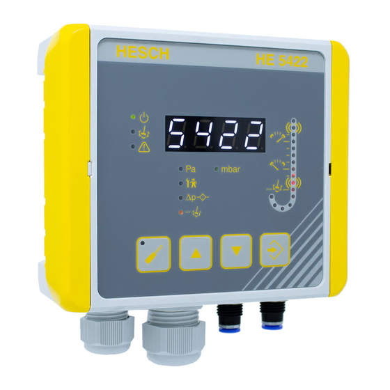
Device Description Summary of device versions 5.1.1 HE 5422 with polycarbonate housing Front view HE 5422 with polycarbonate housing HE 5422 Operating Instructions # 342338 | Version 1.3... -
Page 18: He 5422 Hd With Die-Cast Aluminium Housing
5.1.2 HE 5422 HD with die-cast aluminium housing Front view HE 5422 with die-cast aluminium housing HE 5422 Operating Instructions # 342338 | Version 1.3... -
Page 19: Electrical Commissioning
Warning of material damage caused by electrostatic charge! Observe the safety measures according to DIN EN 61340-51/-3 to avoid electrostatic discharge! Note! Work on the electronic systems may only be carried out by qualified specialist personnel. HE 5422 Operating Instructions # 342338 | Version 1.3... -
Page 20: Read Out And Set Password
Repeat steps 3 and 4 to set the second and third digits. After the last digit has been confirmed with ENTER, HE 5422 appears on the display and the control system starts. HE 5422 Operating Instructions # 342338 | Version 1.3... -
Page 21: Supply Voltage
2. Connect existing supply voltage 100 - 240 VAC or 24 VDC. The device has both connections. 3. Connect PE conductor. On the HE 5422 HD it is imperative to note that with a 24 VDC supply, the earth must be connected via the PE terminal on the VAC supply. -
Page 22: Inputs
Hose connection Insert hose with 6 mm outer diameter into the connection. Hose disconnection 1. Press the blue retaining ring to open the lock. 2. Pull the hose out of the connection. HE 5422 Operating Instructions # 342338 | Version 1.3... -
Page 23: Display And Control Elements
Display and control elements External display and control elements Status LED on p module Internal display elements on the PCB HE 5422 Operating Instructions # 342338 | Version 1.3... - Page 24 Is linked to the alarm / operation relay of the software. LED lights up when the relay drops out (alarm message). LED goes out when the relay picks up (operation). HE 5422 Operating Instructions # 342338 | Version 1.3...
-
Page 25: Differential Pressure Column
Zeroing Differential pressure column The LEDs are used in normal operation to display the differential pressure. In parameterization mode, the selected parameter value is indicated by the respective LED flashing. HE 5422 Operating Instructions # 342338 | Version 1.3... -
Page 26: Operation
Output test: Relay operation = off Output test: Relay cleaning = off Output test: Relay alarm high = off Output test: Relay alarm low = off HE 5422 Operating Instructions # 342338 | Version 1.3... -
Page 27: Differential Pressure Measurement
Figure 13 shows the pressure connections using the example of the device variant with polycarbonate housing. The connections are arranged identically on the heavy duty version with die-cast aluminium housing. Connections for differential pressure measurement using the example of the variant with polycarbonate housing HE 5422 Operating Instructions # 342338 | Version 1.3... - Page 28 Measuring range of the sensor High alarm Precoating Upper threshold Cleaning start Lower threshold Delay time Cleaning stop 5 minutes Low Alarm Start cleaning Time Post- Cleaning cleaning Cleaning Alarm relay HE 5422 Operating Instructions # 342338 | Version 1.3...
-
Page 29: Special Key Combinations / Operating Instructions
Press the UP and ENTER keys simultaneously to activate the precoating function. The display shows PrE alternating with other values. Press the DOWN and ENTER keys simultaneously to deactivate the precoating function. PrE disappears from the display. HE 5422 Operating Instructions # 342338 | Version 1.3... -
Page 30: Parameterization
All corresponding parameters are also displayed negatively.) OFF, 0…Sensor max. High-Alarm [mbar] mbar 30.0 Threshold for the high alarm message. If exceeded, the relay contact is closed. HE 5422 Operating Instructions # 342338 | Version 1.3... - Page 31 Δp-Offset [mbar] Sensor min.…Sensor mbar The offset is added to the max. currently measured differential pressure. HE 5422 Operating Instructions # 342338 | Version 1.3...
- Page 32 (changeover contact) 0…99.9 BG cleaning interval [h] Cleaning monitoring time. If there is no cleaning within the monitoring time, a background cleaning process with the configured duration is started. HE 5422 Operating Instructions # 342338 | Version 1.3...
- Page 33 The threshold values can be set as desired. There is no logical check. If the values of the lower thresholds are parameterized via the values of the upper thresholds, the cleaning and the pressure display cannot work as expected. HE 5422 Operating Instructions # 342338 | Version 1.3...
-
Page 34: Parameterization With Device Keyboard
The next parameter is offered. Change the next parameter, if necessary. Pressing the PARA key again quits parameterization mode. To return to the parameter menu, the password must be entered again. HE 5422 Operating Instructions # 342338 | Version 1.3... -
Page 35: Parameter Setting With Service Pc
Parameterization with a service PC is recommended when parameterizing multiple devices. The USB / TTL adapter required for this is available from HESCH. The parameters can be changed using a PC and the "EasyTool Controls 4.0" application. The program can be used to save a configuration or to restore a previously saved configuration. -
Page 36: Reset Factory Settings
(see 9.1 Parameter table). If no password has been assigned, the control system starts automatically after 5 seconds with the factory-set parameters (see 9.1 Parameter table). HE 5422 Operating Instructions # 342338 | Version 1.3... -
Page 37: Operation
Note! All digital inputs of a system refer to the same earth (-). It is allowed to use one earth line for all inputs. HE 5422 Operating Instructions # 342338 | Version 1.3... - Page 38 3. The measured value is frozen/held. Supply voltage Please only connect 24 VDC or 100 - 240 VAC! For HE 5422 HD it is imperative to note the following: When connecting the 24 VDC supply, earth must be connected via the PE terminal of the VAC mains supply.
- Page 39 The current output is not galvanically isolated. 0-10 V 0 (4) – 20 mA HE 5422 Operating Instructions # 342338 | Version 1.3...
-
Page 40: Function Hold
"hold time after run-on". If the hold input is still active after the configurable "maximum hold time", i.e. the edge rises again, the hold function is automatically ended. HE 5422 Operating Instructions # 342338 | Version 1.3... -
Page 41: Error Messages
Adjust the configured The low alarm LED The differential pressure falls flashes: below the set threshold for more pulse and pause than 5 minutes without reaching times. the post-cleaning threshold. HE 5422 Operating Instructions # 342338 | Version 1.3... - Page 42 Alarm LED flashes: Check the connection cable between the I/O unit and the control unit for damage. Possibly the RJ-45 connector is not properly engaged. Snap the connector back into place. HE 5422 Operating Instructions # 342338 | Version 1.3...
-
Page 43: Maintenance And Service
Dispose of assembled PCBs in a proper manner. Service HESCH Industrie-Elektronik GmbH Boschstraße 8 31535 NEUSTADT GERMANY Phone: +49 5032 9535-0 Fax: +49 5032 9535–99 Internet: www.hesch-automation.com Email: info@hesch.de HE 5422 Operating Instructions # 342338 | Version 1.3... -
Page 44: Declaration Of Conformity
Declaration of conformity HE 5422 Operating Instructions # 342338 | Version 1.3... - Page 45 HE 5422 Operating Instructions # 342338 | Version 1.3...
Need help?
Do you have a question about the HE 5422 and is the answer not in the manual?
Questions and answers