
Related Manuals for HESCH HE 5731 Compact


Summary of Contents for HESCH HE 5731 Compact
- Page 1 HE 5731 Compact / Modular Solenoid valve control Operating instructions (English translation German original version) # 373344 | Version 1.5...
- Page 2 Editor: HESCH Industrie-Elektronik GmbH, Documentation Department Copyrights © Copyright 2021 HESCH Industrie-Elektronik GmbH. All rights reserved. The content including pictures and the design of these operating instructions are subject to copyright protection and other laws for the protection of intellectual property. The distribution or modification of the contents of this manual is not permitted.
-
Page 3: Table Of Contents
Table of Content FOREWORD .............................. 5 1.1..........................5 NSTRUCTIONS FOR USE 1.2............................5 EGAL PROVISIONS SAFETY INFORMATION ..........................6 2.1....................... 6 YMBOLS AND ASIC AFETY NSTRUCTIONS 2.2....................7 AFETY IN THE INDIVIDUAL OPERATING PHASES TECHNICAL DATA ............................9 DEVICE DESRIPTION .......................... - Page 4 Foreword Document history Date/ Description Author Version 04.10.2018 Translation / 1.0 12.12.2018 Modification of name plate for sole- / 1.1 noid valve control and control unit Chapter Electrical Commissioning: 15.08.2019 Note added for entering password / 1.2 prior to commissioning. Chapter 5 Electrical Commissioning: Note for entering password deleted, Chapter 5.2 Readout and set pass-...
-
Page 5: Foreword
Information about inspection tasks and disposal. 1.2. Legal provisions Manufacturer HESCH Industrie-Elektronik GmbH, Boschstraße 8, 31535 NEUSTADT, GERMANY Intended Use The solenoid valve control HE 5731 is used for cleaning industrial filter systems. The number of valves is from 1 to a maximum of 64, and can be scaled, using modular exten- sion units. -
Page 6: Safety Information
Safety Information 2. Safety Information 2.1. Symbols and Basic Safety Instructions This chapter contains important safety regulations and notes. To protect against personal injury and material damage, it is necessary to read this chapter carefully before working with the device. Symbols used The following symbols are used in this manual. -
Page 7: Safety In The Individual Operating Phases
Safety Information 2.2. Safety in the individual operating phases When installing the control unit and during operation, the following safety instructions must be observed. Danger of Electrocution! Before working on the device, switch off all power supplies used. The electrical cables must be laid according to the respective national regula- tions (in Germany VDE 0100). - Page 8 Technical data Explosion Prevention! The device is suitable for use in explosion zone 22. Before opening the device, it is essential to ensure that no explosive environmental condi- tions, such as dust generation, exist. Troubleshooting! At the beginning of troubleshooting, all possible sources of faults on addi- tional devices or supply lines (measuring lines, wiring, downstream de- vices) should be taken into consideration.
-
Page 9: Technical Data
Technical data 3. Technical data Intended use: Solenoid valve control for cleaning industrial filter systems Models: HE 5731 in compact housing as master control with 16 valve outputs maximum HE 5731 operating unit as control panel built- in casing (the valve outputs are located on the control unit) ... - Page 10 Technical data Housing: Polycarbonate Device designation Housing dimensions: Compact housing 231 × 125 × 90 mm Modular 200 × 122 × 30 mm (panel mounting) Modular 192 × 128 × 63 mm (control unit) Connection set for 3 × M32×1.5 with multiple sealing insert for 6 cables the compact housing 3 ×...
-
Page 11: Device Desription
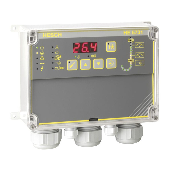
Device desription 4. Device desription The solenoid valve control HE 5731 is available in different versions. 4.1. Overview 4.1.1. HE 5731 Compact HE 5731 (Compact) HE 5731 E (Expansion unit) in Compact housing HE 5731 Operating instructions # 373344, Version 1.5... - Page 12 Device desription HE 5731 (Compact) Connections 4.1.2. HE 5731 Modular The operating unit HE 5731 can be installed with a distance of up to 100 metres away from the control unit. The operating unit itself has no valve outputs. The valve outputs are located on the control unit (see Figure 6).
- Page 13 Device desription HE 5731 Operating unit HE 5731 (Modular) Operating unit Rear panel HE 5731 (Modular) Operating unit HE 5731 Operating instructions # 373344, Version 1.5...
- Page 14 Device desription HE 5731 Control unit The control unit for standard rail mounting has 16 valve outputs maximum. 4 control units maximum can be connected to the operating unit (see also chapter 6.3). Figure 6 shows the control unit where external display devices are connected via a con- nection adapter (see chapter 10 Options).
-
Page 15: Display And Operating Elements
Device desription 4.2. Display and Operating Elements HE 5731 Display and Operating Elements Symbols Meaning Operating message Cleansing active Alarm active Pulse time Break time The number of valves is shown in the display and can be changed Post-cleaning cycles are shown in the display and can be changed Total / partial cycle is shown in the display and can be changed... - Page 16 Device desription Symbols Meaning PARA key: parameterisation mode On/Off UP key: increase the displayed value DOWN key: decrease the displayed value ENTER key: Confirm the displayed value TEST key: Test mode On/Off Display Normal operation: current differential pressure, cur- rent valve ...
-
Page 17: Differential Pressure Column
Device desription 4.3. Differential pressure column Delta-p-measuring range High alarm Upper threshold – start cleaning Lower threshold – stop cleaning Low-Alarm Post-cleaning threshold Zeroing Differential pressure column In normal operation, the LEDs display the differential pressure. In parameterization mode, the selected parameter value blinks to show that it is operational. HE 5731 Operating instructions # 373344, Version 1.5... -
Page 18: Assembly
The special regulations must be observed, see chapter 2.2 Safety in the individual operating phases. 5.1. Dimensions 5.1.1. HE 5731 Compact Dimensions of compact housing (without screw connections) HE 5731 Operating instructions # 373344, Version 1.5... - Page 19 Drilling jig #373222 (only for the operating unit HE 5731 Modular) Note! Upon receipt, check the delivery for completeness and visible defects. In the event of a complaint, contact your responsible HESCH representative immediately HE 5731 Operating instructions # 373344, Version 1.5...
-
Page 20: Electrical Commissioning
Electrical Commissioning 6. Electrical Commissioning Before switching on the device, observe the following points: Danger of Electrocution! Electrical installation must only be carried out when the power is discon- nected. Danger of Electrocution! Work on the electronics may only be carried out by qualified personnel. Explosion prevention! The device is suitable for use in explosion zone 22 with closed lid only. -
Page 21: Read Out And Set Password
AC and device versions only with 24 V DC supply voltage. 6.2.1. Compact housing Open the housing on the right hinge lock using a slotted screwdriver (Figure 12): Opening the housing of the HE 5731 Compact HE 5731 Operating instructions # 373344, Version 1.5... - Page 22 Electrical Commissioning HE 5731 Compact with 24 V DC supply voltage (connection adapter optional) HE 5731 Compact with 24 V DC supply voltage (without connection adapter) See name plate for supply voltage value (on the right of the housing). (There are devices with 100…240 V AC and devices with 24 V DC supply voltage).
- Page 23 Electrical Commissioning Connecting master device (24 V DC version) with extension unit (24 V DC) Connecting master device (100…240 V AC version) with extension unit (24 V DC) 6.2.2. Panel mounting housing The supply voltage is connected centrally at the control unit. The operating unit is con- nected to the 24 V DC supply via a patch cable (CAT 5 or better).
- Page 24 Electrical Commissioning 6.2.3. Communication Serial communication is enabled by connecting the “A” and “B” connections, from device to device. The coder switch provides the logical position in the sequence of the controls, which do not have to correspond to the cabling sequence. Caution! The A and B lines must not be confused with each other.
- Page 25 Electrical Commissioning 6.2.4. Bus structure Warning! Having a star-formed cabling or branches of the serial connection is not allowed. HE 5731 Operating instructions # 373344, Version 1.5...
-
Page 26: Valve Connections
The control extends the effective pause time automatically to the above ratio. The software version can be determined by a serial number query https://www.hesch.de/index.php?id=133&L=1. Note! All valve outputs of a system refer to the same ground (-). It is permitted to use one ground wire for multiple valves. - Page 27 Parameterisation 6.3.1. Coding switch Coding switch for the device order. The device number of the communication indicates the controlled order of valves, independent of the order of wiring. The device number “5“ is for the operating and control unit without effec- tive valve connection.
-
Page 28: Parameterisation
Parameterisation 7. Parameterisation 7.1. Parameterisation with Device Keyboard Press the PARA key to change the values of the system parameters. A flashing LED indicates the value currently to be changed. If a password has been assigned, cod is displayed. Press the ENTER key. Press the UP and DOWN keys to enter the password digit by digit. -
Page 29: Parameter Table
Parameterisation 7.2. Parameter table Default Pre-assignment Parameter Adjustment range setting 0…999 Password 3-digit number that must be entered before parameters can be changed. 0 = no password protection Pulse time 0.01…9.99 s 0.10 s 0.10 s 1.0 s …999 s Break time 5.0 s 5.0 s... - Page 30 Parameterisation Adjustment Default Pre-assignment Parameter range setting Lower threshold [mbar] OFF, 10.0 mbar 10.0 mbar 0.0…500.0 mbar (at 0…35 mbar If underrun, dp-dependent cleaning stops. measuring range) End of dp cycle 25.0 mbar (at 0…90 mbar measuring range) 130,0 mbar (at 0…450 mbar measuring range) Low-alarm [mbar]...
- Page 31 Parameterisation The following parameters can only be changed with the "EasyTool Controls" program: (see chapter 7.4 Parameterisation with Service PC) Factory Pre- Parameter Adjustment range setting assignment Delta-p filter Filter constant for damping the 0.1…10.0 s 2.0 s 2.0s Delta-p measurement. Delta-p working range Defines the working range below the upper threshold in % of the...
-
Page 32: Offset For Zeroing
When parameterising several devices, parameterisation with a service PC is recom- mended. The USB / TTL adapter required for this is available from HESCH. The parame- ters can be changed via PC and the "EasyTool Controls" program. The program can be used to save a configuration or to restore a saved configuration. -
Page 33: Enable / Disable Precoating
Operation of the control 7.5. Enable / Disable Precoating Enable: Press the TEST key and the UP key simultaneously. “PrE” is displayed alternately with other information. Disable: Press the TEST key and the DOWN key simultane- ously. After reaching the first cleaning threshold (increased by the precoating), the precoating is automatically disabled. -
Page 34: Operation Of The Control
Operation of the control 8. Operation of the control 8.1. Normal Operation Operation is started by applying the supply voltage. The valve cleaning is controlled via the inputs and outputs of the device. Note! All valve outputs of a system refer to the same mass (-). It is permitted to use one ground line for several inputs. -
Page 35: Test Function
Operation of the control 8.2. Test Function Press the TEST key to perform a function test of the valves. Select the desired valve with the UP / DOWN keys. Press ENTER (The selected valve is permanently oper- ated with the stored pulse and pause time). If necessary, test the next valve. -
Page 36: Differential Pressure Measurement
Operation of the control 8.4. Differential pressure measurement External dis- External play device display device Differential pressure measurement (connection adapter optional) External display device Differential pressure measurement (without connection adapter) 2-wire sensors, such as HE 5409, HE 5410, HE 5421 with communication of the power signal to an external display device (see chapter 10 Options). - Page 37 Error messages The differential pressure (does not apply to devices with pure time control) is measured externally and passed on as a 4…20 mA signal to the control. The signal can be con- nected to both the master, as well as to one of the extension units. In addition, there is the possibility that the 4…20 mA signal can be connected to an external dis-play device.
-
Page 38: Error Messages
Error messages 9. Error messages Display Cause Action “buS” is blinking in the The sum of the valves set on Check the set total valve display, the alarm LED the devices is smaller than number is illuminated the set total valve number ... - Page 39 Error messages Display Cause Action The permissible valve current Check the indicate valve The LED flashes. of 1 A has been exceeded for short-circuit The display shows the relevant valve Check the valve in question Check if the valve plug is connected correctly.
- Page 40 Options Display Cause Action The high alarm LED The differential pressure ex- Adjust the set pulse and ceeds the set limit pause times flashes Check the filter element Check the solenoid valve, that it is mechani- cally functioning without defects or errors ...
-
Page 41: Options
17–19. The terminal extender can be purchased at HESCH (article number # 57310089). This chapter only concerns devices that are designed to use an optional connection adapter. - Page 42 Options Open the housing cover (see Figure 12). Put the terminal extender with the pin header onto the terminals 17-19. Connect the external device (see Figure 25). Close the housing cover. Terminal extender current input / output (article number # 57310089) Note! If no external device is connected, the analogue output must be bridged.
- Page 43 Options Differential pressure measur- Device with differential or ing with galvanically separated ana- 2-conductor sensor, e.g.. logue input. Max. burden analogue output = 400 Ω. HE 5409, HE 5410 or HE 5421. Terminal extension / terminals HE 5731 Operating instructions # 373344, Version 1.5...
-
Page 44: Pressure Switch
Options 10.2. Pressure switch Optionally, the enable input (EN) can be used for connecting a pressure switch for con- trolling the system. “ENABLE” is then without function at this input. Optional use of the pressure switch: The pressure switch (p) is used to control the mechanical valve function. -
Page 45: Maintenance And Service
Dispatch metals and plastics for recycling. Electrical and electronic components must be Disposal collected separately and disposed of accordingly. Dispose of assembled printed circuit boards professionally. Service HESCH Industrie-Elektronik GmbH Boschstraße 8 31535 NEUSTADT GERMANY Phone: +49 5032 9535-0 Fax: +49 5032 9535–99... -
Page 46: Declaration Of Conformity
Declaration of conformity Declaration of conformity You will find the declaration of conformity on www.hesch.de. HE 5731 Operating instructions # 373344, Version 1.5...
Need help?
Do you have a question about the HE 5731 Compact and is the answer not in the manual?
Questions and answers