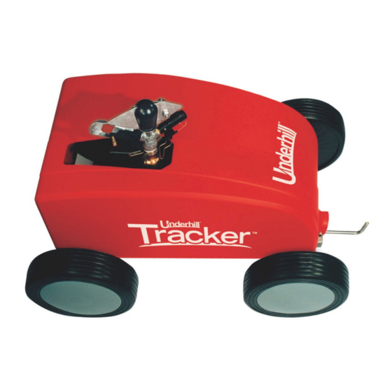
Summary of Contents for Underhill Tracker
- Page 1 T-400 Portable Irrigation Machine Assembly Instructions and Operation Manual Underhill International Corporation 25782 Obrero Drive Unit C Mission Viejo, CA 92691 Phone: 949 305-7050 Fax: 949 305-7051 www.underhill.us...
-
Page 2: Table Of Contents
Locate the Pull Rope Release Mechanism ..................... 1 1 Locate the Auto Shut-off ............................ 1 1 Operation ............................... 1 3 Required Operating Pressure .......................... 1 3 Speed Adjustment .............................. 1 3 Set-up to Water ................................ 1 3 Maintenance ............................ 1 4 Troubleshooting .......................... 1 4 Spare or Replacement Parts ...................... 1 4 Tracker Operation Video ........................ 1 4 Underhill UltraMax Hose Series .................... 1 4 Underhill Tracker Assembly and Operation Instructions... -
Page 3: Tracker Views
Tracker Views Impact Sprinkler w/ #07 nozzle Speed Control Tracker End View Auto Shut-Off Nylon Pull- Rope Pull-Rope Release Mechanism Pull-Rope Drum Hub Cap 1” Supply Valve Hose 1” Brass Quick-Disconnects Tracker Top View Underhill Tracker Assembly and Operation Instructions... -
Page 4: Introduction
Tracker Portable Irrigation Machine Figure 4-1 The Tracker pulls itself up to 360’ in length with the supplied nylon pull-rope to a ground stake and will automatically shut itself off when it’s reach the end of its tether. A 1” supply hose should be 10% longer than the length of area to be watered. -
Page 5: Getting Started
Operating and Maintenance Manual Contents of Tracker Shipping Carton Figure 5-1 Recommended Tools for Assembly The following is a list of tools or other components needed to quickly assemble the Tracker. Tool Description Large crescent wrench ½” Teflon Tape With the proper tools, assembly should take approximately 15-20 minutes. -
Page 6: Assembly Instructions
Locate and understand how the auto-shut-off function operates. Assemble and Install the Wheels Place the Tracker on its side. Insert the one of the hollow aluminum axles into the one of the wheels with the ribs of the wheel facing outward as shown in Figure 6-1. -
Page 7: Assemble And Install The Water Supply Fittings
Figure 7-1 Assemble and Install The Water Supply Fittings Locate the 1” brass threaded inlet on the back of the Tracker. Wrap the male threads of the 1” brass, male to female quick-connect with Teflon tape and thread into this inlet, see Figure 7-2. -
Page 8: Install The Impact Sprinkler
Install the Impact Sprinkler Wrap the male threads of the impact sprinkler with 3 or 4 turns of Teflon tape and thread into the 1” outlet on top of the Tracker, see Figure 8-1. Tighten ¼ turn further with a crescent wrench. -
Page 9: Tracker Operation
When connected to a 1” diameter hose (to support the flow demand of the impact sprinkler), with a minimum of 50 Psi, the Tracker will automatically pull itself along the nylon cord, then automatically shut off once it’s reach the ground stake. - Page 10 Figure 10-2 below automatically shutting off the Tracker. Tracker “Off” Figure 10-2 Note: If the Tracker is observed to no longer pull it self along the nylon rope, then the cone-shaped inlet of the diaphragm is clogged w/ debris and needs to be cleaned.
-
Page 11: Locate The Pull Rope Release Mechanism
Locate the Pull Rope Release Mechanism Open the red cover to expose the interior of the Tracker. There is a large brass knob on the side of the pull-rope drum. Note how the brass knob has to parallel flat sides see Figure 11-1. - Page 12 Figure 12-1. This latch is located to the right of the pull-cord spool under the red cover. Tracker “On” Position Tracker “Off” Position Auto Shut-Off Reset Figure 12-1 The Tracker is now ready to irrigate. Underhill Tracker Assembly and Operation Instructions...
-
Page 13: Operation
Operation Now that the Tracker is fully assembled, connect a 1” hose to a water source and then other end to the quick connect fitting of the Tracker. Required Operating Pressure The Tracker requires a minimum of 50 Psi at the inlet side of the machine. If delivery pressure is measured to be the same or lower at the water source, this could impact the product’s performance where it may not operate as expected. -
Page 14: Maintenance
A separate Troubleshooting Guide can be found on Underhill’s web site via the following web link; http://underhill.us/markets/golf/watering-acc/199-tracker#resources Spare or Replacement Parts An exploded view of the internal parts of the Tracker can be found on Underhill’s web site via the following web link; http://underhill.us/markets/golf/watering-acc/199-tracker#resources Tracker Operation Video A video of the Tracker in operation can be found on Underhill’s web site via the following web... - Page 15 Underhill International Corporation 15251 Barranca Parkway, Irvine, CA 92618 Phone (949) 305-7050 Fax (949) 305-7051 www.underhill.us...


Need help?
Do you have a question about the Tracker and is the answer not in the manual?
Questions and answers