
Related Manuals for IKA LOGIC SP209 Series

Summary of Contents for IKA LOGIC SP209 Series
- Page 1 SP209 series datasheet and user manual SP209 and SP209i 9 channels, 200 MSPS logic analyzer with industrial inputs option www.ikalogic.com | support@ikalogic.com December 28, 2020...
-
Page 2: Table Of Contents
SP209 Series User Manual SP209 / SP209i Contents SP209 Series overview Typical applications ........ - Page 3 SP209 Series User Manual SP209 / SP209i Ordering information and customer support Accessories and maintenance Certifications and regulations Safety information Symbols definitions ........
-
Page 4: Sp209 Series Overview
SP209 / SP209i SP209 Series overview SP209 series logic analyzers and protocol decoders o er in depth analysis of logic signals and protocols with 200MHz (5ns) timing resolution. 9-channel operation allows 8-bit parallel data to be captured along with a clock or strobe signal. -
Page 5: Product Highlights
SP209 Series User Manual SP209 / SP209i • ADC diagnostic Figure 3: Example of logic signals captured and analyzed by SP209 logic analyzer Product highlights • Schmitt trigger input stages with adjustable thresholds • 200 MHz sampling rate, with all 9 channels used. -
Page 6: Warning
SP209 Series User Manual SP209 / SP209i Warning Read safety information section carefully before using this instrument. (c) Ikalogic SAS 2019 6/23... -
Page 7: Main Characteristics
SP209 Series User Manual SP209 / SP209i Main characteristics Operating conditions Temperature 10°C to 40°C Relative humidity < 80% non condensing Altitude < 2000m Timing and measurements Sampling rate (MAX.) 200 MSPS External clock Max rate (State mode) 50 MHz... -
Page 8: Sp209(I) Interfaces
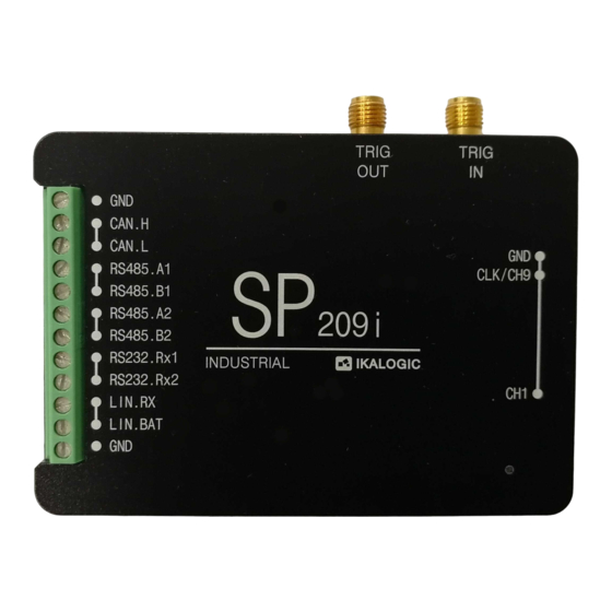
SP209 Series User Manual SP209 / SP209i Input voltage 0.25 V SP209(i) Interfaces SP209(i) logic analyzer ports and interfaces are shown in the diagram below: Figure 4: SP209i ports and interfaces 1. Status LED 2. 9-CH logic probes input 3. Trigger OUT SMA connector 4. -
Page 9: Principle Of Operation
Principle of operation SP209 Series logic analyzers connects to a computer via a USB cable. A free so ware - called ScanaStu- dio - is used to configure the device and display captured signals. The so ware can also be used to further analyze the captured samples by decoding protocols like I2C, SPI or UART. -
Page 10: External Trigger Out Specifications
SP209 Series User Manual SP209 / SP209i • A or B (whoever triggers first) Finally, an external trigger output is always active, in all modes and generates a trigger pulse whenever a trigger condition is met and a capture starts. Signal specifications for External trigger input and output are detailed in the following section. -
Page 11: External Trigger In Specifications
SP209 Series User Manual SP209 / SP209i External trigger IN specifications Figure 6: External trigger IN timings The Trig In port allows to start acquisition on an external event generated by another instrument. The minimum pulse width (T1) is 5ns. Polarity can be set in so ware. The input impedance is also so ware selectable (100k Ωor 50 Ω). -
Page 12: Rs485 Receiver Specifications
SP209 Series User Manual SP209 / SP209i • LIN bus receiver Please refer to the marking on SP209i casing for exact pinout. RS485 receiver specifications Transceiver MPN MaxLinear XR33180 Maximum baudrate 50 Mbps Common Mode Operating range -7 V to +12 V Common Mode Input Impedance 48 k Ω|| 10 pF... -
Page 13: Lin Receiver Specifications
It is recommended to connect the ground of the industrial bus being measured to the nearest ground screw terminal (Refer to marking on SP209i casing for industrial connector pinout). What’s in the box SP209 series is shipped with the following items: 1. SP209(i) device (c) Ikalogic SAS 2019... -
Page 14: Unpacking And First Usage
SP209 Series User Manual SP209 / SP209i 2. USB cable (micro-B to A) 3. 10 leads micro-grabber probes set (9 signals + 1 ground) 4. 10 slots cable comb (to group logic probes together) 5. SMA anti-dust covers Unpacking and first usage We recommend the user to start by identifying all the di erent components that are provided. -
Page 15: Capturing Your First Signal
You can adjust the capture duration by adjusting the number of samples in the device configuration tab. Mechanical data All SP209 series devices casing are manufactured from anodized aluminum, able to withstand heavy duty usage in various harsh environments. All markings are laser engraved, ensuring important pinout information is not lost over time. -
Page 16: Model Sp209I
SP209 Series User Manual SP209 / SP209i Model SP209i Weight: 105 gm Figure 7: SP209i dimensions (mm) (c) Ikalogic SAS 2019 16/23... -
Page 17: Model Sp209
SP209 Series User Manual SP209 / SP209i Model SP209 Weight: 90 g Figure 8: SP209 dimensions (mm) (c) Ikalogic SAS 2019 17/23... -
Page 18: Probes
SP209 Series User Manual SP209 / SP209i Probes Probes cables are made of 24AWG extra flexible silicone wires. All wires are black colored, but every wire has a white marking tube with the channel number (e.g. “1” or “GND”) and a colored sticker on the probe tip. -
Page 19: So Ware Technical Requirements
SP209 Series User Manual SP209 / SP209i So ware technical requirements Download ScanaStudio so ware on www.ikalogic.com so you can use your device on your favorite platform. SP209(i) and ScanaStudio were tested to supports the following platforms: • Windows 7/8/10 •... - Page 20 SP209 Series User Manual SP209 / SP209i in a particular installation. If this equipment does cause harmful interference to radio or television reception which can be determined by turning the equipment o and on, the user is encouraged to try to correct the interference by one or more of the following measures: •...
-
Page 21: Safety Information
SP209 Series User Manual SP209 / SP209i Safety information This product complies with safety standards IEC NF/EN 61010-1: 2010, IEC NF/EN 61010-2-030 and UL 61010-1: 2015 To prevent possible electrical shock, fire, personal injury, or damage to the product, read all safety information before you use the product. The following international symbols are used on the product and in this manual. -
Page 22: Limited Warranty & Limitation Of Liability
SP209 Series User Manual SP209 / SP209i • Do not use the product if it operates incorrectly. • Before use, inspect device casing, probes, test leads and accessories for mechanical damage and replace if damaged. • Never attempt to repair a defective device. Contact a er-sale service. -
Page 23: Document Revisions
SP209 Series User Manual SP209 / SP209i EXPRESS OR IMPLIED, INCLUDING BUT NOT LIMITED TO ANY IMPLIED WARRANTY OF MERCHANTABILITY OR FITNESS FOR A PARTICULAR PURPOSE. IKALOGIC SHALL NOT BE LIABLE FOR ANY SPECIAL, INDIRECT, INCIDENTAL OR CONSEQUENTIAL DAMAGES OR LOSSES, INCLUDING LOSS OF DATA, WHETHER ARISING FROM BREACH OF WARRANTY OR BASED ON CONTRACT, TORT, RELIANCE OR ANY OTHER THEORY.
Need help?
Do you have a question about the SP209 Series and is the answer not in the manual?
Questions and answers