Table of Contents
Advertisement
Quick Links
Tracking Solutions
Embedded Antenna design
GPS&Wireless solutions Provider
Part Number: NB-5
Doc Type : User Manual
Doc Id: WI-RD-E-054
Reversion : V1.0
Copyright © 2020 San Jose Technology, Inc. All Rights Reserved.
This document contains information that is the property of SANAV. This document may
not be copied, reproduced, reduced to any electronic medium or machine readable form,
or otherwise duplicated, and the information herein may not be used, disseminated or
otherwise disclosed, except with the prior written consent of SANAV.
1
Advertisement
Table of Contents

Related Manuals for San Jose Technology NB-5


Summary of Contents for San Jose Technology NB-5
- Page 1 Doc Id: WI-RD-E-054 Reversion : V1.0 Copyright © 2020 San Jose Technology, Inc. All Rights Reserved. This document contains information that is the property of SANAV. This document may not be copied, reproduced, reduced to any electronic medium or machine readable form, or otherwise duplicated, and the information herein may not be used, disseminated or otherwise disclosed, except with the prior written consent of SANAV.
-
Page 2: Table Of Contents
Contents Specifications ........................ 3 NB5 Function Overview ................... 4 NB5 Tracker Installation ..................8 Cutting Tools ........................ 12 NB5 SMS Command Quick Setting ..............15 STEP 1: Set up Username/Password (Optional) ........17 STEP 2: Set up Phone Book and Security Phone Number (Optional)19 STEP 3: Set up HA ID .................. -
Page 3: Specifications
Specifications GSM Module: uBlox SARA U201 3G: 800/ 850/ 900/ 1900/ 2100MHz GSM Frequency: GSM: 850 / 900/ 1800/ 1900MHz 3G Transmission: Power class 3 (24 dBm) for WCDMA/HSDPA/HSUPA mode GPS Module: u-blox G8030 support NMEA0183 Sensitivity: -164 dBm Channels/ Frequency: 72 Channels/ GPS/QZSS/GLONASS Cold/Warm <26 seconds TTFT(Hot/Warm/Cold):... -
Page 4: Nb5 Function Overview
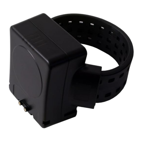
Waterproof: IP68 NB5 Function Overview 1. Basic Function Introduction NB5 is multi-functional electronic monitoring ankle bracelet with GPS/3G/RF monitoring technology. With electronic monitoring technology, you have ability to reliability track user’s location. NB5 utilizes GPS and 3G services to upload the RMC sentences containing latitude, longitude, date and time to assigned monitoring center. - Page 5 Charge 3 hours to provide above 30-hour operation (each report/1 minutes, no general alarm) 3. Front View STATUS LED (from left to right): GPS Positioning LED (Blue): While the device gets GPS fixed, the GPS light will stay on. GSM LED (Red): While the device gets GSM fixed or in normal operation, the GSM light will flash every 3 seconds.
- Page 6 charged, the CH LED will stay on. Unplug the charger when the device is fully charged. In this situation, CH charger LED will be off. Charge Socket (Red circle): Please make sure to use San Jose original charger and charging pack to protect your equipment. 11F., No.2, Sec.
- Page 7 4. Back Cover 5. Wall Charger 11F., No.2, Sec. 4, Jhongyang Rd., Tucheng Dist., New Taipei City 236, Taiwan (R.O.C.) Tel: 886-2-22694456|Fax: 886-2-22694451|service@unictron.com www.unictron.com www.sanav.com...
-
Page 8: Nb5 Tracker Installation
NB5 Tracker Installation Note: The device must be fully charged prior to installation. Remember to wear a pair of socks for comfortable attaching. Circle the user’s leg with strap and installation height of NB5 will be 8-10cm from an outer ankle. Circle the user’s leg with strap and determine the length of the strap that leaves approximately 20-30 mm (2-3... - Page 9 Please note that the cutting line should be on the groove between two scales for easy cutting and wearing purpose. While cutting the strap by using the dedicated strap, it should proceed with 3 stages cutting procedures. Keep cutter and strap at 90-degree angle to make sure that the cutting edge should be flat.
- Page 10 Cut procedures are completed Put up the Jelly cover at the end of strap. Please refer to NB5 Jelly cover assembly SOP. Fix the strap clip at the end of strap. Insert the strap with strap clip into the socket chamber at rear cover right side.
- Page 11 Activated. Start tracking. While using wall charger, aim the charger connector (female) to NB5 charge socket (male), push till the end to lock the device. Unplug the wall charger in correct direction to avoid from charge socket or charger malfunction. Connected and charged.
-
Page 12: Cutting Tools
Cutting Tools Make sure that the front side of the cutting tool faces to you and that the strap’s entrance direction. The spare blades are restored in the red rectangle. Check that the blade is right on the block that should be cut. 11F., No.2, Sec. - Page 13 After making sure the location is right, push the top of cutting tool to cut the strap Exchange the blade if needed. Release the screw ant then remove the blade. Note that releasing completely the screw is not necessary. Notice the direction of the blade since we need to install the spare blade on the same direction later.
- Page 14 Install the blade. Please make sure the edge of the blade is inside the white area on the cutting tool. Push the top of cutting tools to the bottom so that the blade is back to the right place and screw it up.
-
Page 15: Nb5 Sms Command Quick Setting
NB5 SMS Command Quick Setting SMS Command setting 1. Any setup command must be started with a “#” sign and ended up with a “*” sign. Please note that all the characters which include “#”, “*” and comma (,) should be HALFWIDTH form. 2. - Page 16 SETP 0: Send the Alarm-Off Command Once the events such as strap violation and device tamper are triggered, NB5 will send the reports with the alarm message followed by the beep sound and vibration. This command is used to deactivate the alarm status, and then the device will be detecting the events. Setup Format:#<User Name>, <Password>, <Function Mode>* Example:#username,0000,alarmoff* ‘...
-
Page 17: Step 1: Set Up Username/Password (Optional)
STEP 1: Set up Username/Password (Optional) Set up Username Generally, SMS command execution needs correct user name (I.D) with password, or it will remain the same setting. The SMS command default user name is “username”. It can be changed by following the command format. For example, entering the SMS command as the following allows user to change the user name from “username”... - Page 18 Set up Password Generally, SMS command execution needs correct user name with password, or it will remain the same setting. The SMS command default password is “0000”. It can be changed by following the command format. For example, entering the SMS command as the following allows user to change the password from “0000” to a new password “1111”.
-
Page 19: Step 2: Set Up Phone Book And Security Phone Number (Optional)19
STEP 2: Set up Phone Book and Security Phone Number (Optional) Security Phone Number allows limited administrators to manage and change the settings of the bracelet. When the Security Phone Number is set, even the User Name and Password are correct, if the setup phone number is not matched, the setup or any change will be invalid. -
Page 20: Step 3: Set Up Ha Id
End sign. Table: Security Phone Number Setup Format Description Situation Message Reply Setup Succeeds [username] + Device phone book is updated. Table: Security Phone Number Setup Response Description STEP 3: Set up HA ID The bracelet (HA) ID is set for identification. The ID number ranges from 1 to 9999. The ID will be shown in the reports. -
Page 21: Setp 4: Set Up Rf Detection (Optional)
SETP 4: Set up RF Detection (Optional) This command is for the bracelet with RF capability. Once the RF Detect function is turned on, the device can communicate with the Home Unit. This command can be used for site survey when installing Home Unit. When RF test mode (the 2 parameter) is turned on, the bracelet will beep when it receives the RF signal from Home Unit. -
Page 22: Setp 5: Set Up Rf Power
SETP 5: Set up RF Power The ankle bracelet RF transmit power can be set for Home Unit curfew range adjustment. There are totally 8 levels of RF transmit power that can be set. The stronger the RF transmit power is, the wider the curfew range would be. -
Page 23: Step 6: Set Up Apn For 3G Service
STEP 6: Set up APN for 3G Service Access Point Name (APN) is a protocol that typically allows a user's device to access the internet using the mobile phone network. It is a network identifier used by a mobile device when connecting to a GSM carrier. The carrier will then examine this identifier to determine what type of network connection should be created. -
Page 24: Step 7: Set Up Url And Tcp/Udp Ip Address
Situation Message Reply Setup Succeeds [username] +, Device GPRS APN is updated. Table: APN Setup Response Description STEP 7: Set up URL and TCP/UDP IP Address Set up URL This SMS command is for setting up a specified URL (Uniform Resource Locator) or IP address of HTTP protocol server where the bracelet will transmit GPS (GPRMC) positioning data to for real time GPS tracking as route of the device is set as HTTP mode. - Page 25 Set up TCP/UDP IP Address This SMS command is for setting up a specified TCP or UDP protocol based server where the bracelet will transmit GPS (GPRMC) positioning data for real time GPS tracking as route of the device is set as TCP or UDP mode.
-
Page 26: Step 8: Set Up Route For Data Transmission
STEP 8: Set up Route for Data Transmission This SMS command set up the route that determine in which protocol the device ends up transmitting GPS (GPRMC) positioning data. Please confirm the back-end server protocol type and corresponded URL or IP address with port number before setup. -
Page 27: Step 9: Set Up Auto Report (Optional)
Situation Message Reply [username] +, Device is switching to HTTP mode. Setup Succeeds [username] +, Device TCP is updated. [username] +, Device is switching to SMS mode. Table: Data Transmission Route Setup Response Description STEP 9: Set up Auto Report (Optional) Auto Report setup can enable the bracelet report GPS data automatically during a period of time. -
Page 28: Step 10: Request Imei Number
Situation Message Reply Setup Succeeds [username] + Setup OK. Device Auto Report setting is updated. Setup Fail [username] + Auto Report setting Setup Fail! Incorrect password [username] + Password setup Fail! Incorrect username or [username] + command error command format Table: Auto Report Setup Response Description Step 10: Request IMEI Number IMEI stands for International Mobile Equipment Identification, a unique number for identifying mobile devices... -
Page 29: Appendix 1: Report Data Format
Appendix 1: Report Data Format 357520074257524, $GNRMC,081219.00,A,2457.80821,N,12125.53897,E,0.054,,160720,,,A*6C, AUTO, I0200, 9970, M16, 3782mV, 45, 2.40, 24A5 13E16E FFFF, 10613, 27, 14, FFFF, 10613, Item Name Description IMEI stands for International Mobile Equipment Identification, a unique IMEI number number for identifying mobile devices validity in GSM network. 1. - Page 30 GSM Cell ID MNC Mobile Network Code. The range is 0-999 (1 to 3digits). Location Area Code, The range is 0x0-0xFFFF (2 GSM Cell ID LAC octets) Cell identity. The range is: GSM Cell ID o 2G cell: range 0x0-0xFFFF (2 octets) o 3G cell: range 0x0-0xFFFFFFF (28 bits) Cell identity.
-
Page 31: Appendix 2: Tracker Event List
• 1..90: from -115 dBm to -26 dBm with 1 dBm steps • 91: -25 dBm Energy per Chip/Noise ratio expressed in dB levels: • 0: less than -24 dB ecn0_lev • 1..48: from -24 dB to 0.5 dB with 0.5 dB steps •... -
Page 32: Sms Command Introduction
Note: (1) Any event marks with letter “B” (Bauto…..) represents data which was not able to send to assigned route immediately due to priority or mobile network service is not available. The data will be sent after the issues are cleared. (2) The event marks with letter“L”(LAUTO) represents power saving mode for data transmission. -
Page 33: How To Use Er Command For Erase The Flash
How to Use ER Command for erase the flash This command is to erase the reports restored in the flash memory before. Once the GSM signal is weak or other reasons that cause that the device is not able to send reports to the server, the reports will be restored in the flash memory and re-sent later. -
Page 34: How To Restart The Device
How to Restart The Device Use this SMS command to restart the device remotely. This command allow user to restart the device immediately or in schedule. Setup format: #<User Name>, <Password>, <Function Code>, <interval of restart>* Command: #username,0000,rst,9* Command: #username,0000,rst,now* Description SMS Text Start sign. -
Page 35: Setting Of Restart The Device
Setting of Restart The Device This setting defines the behavior when the device restarts. We can choose which opponent will be restarted such as MCU, GSM and GPS. Setup format: #<User Name>, <Password>, <Function Code>, <Function Code>, <interval of restart>* Command: #username,0000,rst,cfg,7* Command: #username,0000,rst,cfg,6* Description... -
Page 36: Use Poll Command For Acquiring The Position
Use POll Command for acquiring the position This feature is for acquire the device’ position immediately. Once the device has received the POLL command, the POLL message will be sent to the server depending on the route you’ve set. The POLL message will be shown in the “Event” field of the report. Setup Format:#<User Name>, <Password>, <Function Mode 10>* Example:#username,0000,10* SMS Text... -
Page 37: Set Up Fbr Command For Fiber Strap
Set up FBR Command for Fiber Strap FRB feature is for detecting the strap violation. The default setting of “FBR Tamper” detected time is 10 seconds due to fiber characteristic. When the feature is turned on, if the strap is cut, the alarm will be triggered and the device will send the ST reports to indicate the strap violation. -
Page 38: Use Reed Command For Cover Tamper
Use REED Command for Cover Tamper FRB feature is for detecting the Tamper violation. When the feature is turned on, if the cover of the bracelet is opened, the alarm will be triggered immediately and the device will send the DT reports to indicate the strap violation. -
Page 39: Command For Toggling The Buzzer And Vibrator
Command for Toggling the Buzzer and vibrator When the Alarm events (such as ST, DT, Geo-fence event) are triggered, the device will beep and vibrate for notice as well as send the reports. This command is to toggling the beep sound and vibration respectively and configuring the interval of notice. This command only affects the beep sound and vibration when the Alarm events are triggered. - Page 40 Situation Message Reply Buzzer setup succeed [username] +, setup OK. Device buzzer is turned off. / on. Vibrator setup succeed [username] +, vibration motor is disabled. / enabled. Buzzer and Vibrator setup scceed [username] +, setup OK. Buzzer & vibrator setting are updated. Buzzer or Vibrator setup fail [username] +, buzzer or vibrator switch setup fail! Parameter setup fail...
-
Page 41: Power Saving Mode Setup
Power Saving Mode Setup This mode has two part of feature. In Power Saving Mode 0, the battery life can be saved by stopping GPS output temporarily while the device isn’t reporting. This is the default setting. Set <Power Saving Mode> to 0 to enable it such like this command: #username,0000,combo,0*. In Power Saving Mode 1, power save mode will be disabled and the GPS is always on. -
Page 42: Aes128 Encryption Function Setting
AES128 encryption function setting Set <Encryption Mode> to 1 to enable it such like this command: #username,0000,aes,1*. Setup Format: #<User Name>, <Password>, <Function Code>, <Encryption Mode>* Command: #username,0000,aes,1* SMS Text Description Start sign. username Default user name of the device. ... -
Page 43: Tcp Acknowledge Function Setting
TCP acknowledge function setting Set <Function Mode> to 1 to enable it such like this command: #username,0000,tcpack,1*. Setup Format: #<User Name>, <Password>, <Function Code>, <Function Mode>* Command: #username,0000,tcpack,1* SMS Text Description Start sign. username Default user name of the device. ... -
Page 44: Set Up Low Power Reminder
Set up Low Power reminder The user can set the SMS/COTA command to alert user if the battery voltage is low or automatically shut down system when the battery voltage reaches a certain threshold. Setup Format: #<User Name>, <Password>,<Function Code>, <Voltage Value 1>,< Voltage Value 2>* Command: #UserName,0000,LP,3650,50* Description SMS/ COTA Command... -
Page 45: Gsm Cell Information Setting
GSM Cell Information Setting Use this command to switch the display GSM Cell Information in the data of report. Setup Format: #<User Name>, <Password>,<Function Code>, <Mode>* Command: # UserName,0000,cellid,1* SMS/ COTA Command Description Start sign. UserName Default ID of the device. If you have changed the user name, please use the updated one. -
Page 46: Firmware Upgrade Over The Air (Fota) Function
Firmware upgrade Over The Air (FOTA) function Use this command to upgrade firmware from a file on http server. Setup Format: #<User Name>, <Password>,<Function Code>, <URL of firmware>* Command: # UserName,0000,fota,Http://220.128.123.1:8000/NB5-F5359-0609201617-VA1.0.3-OTA(00383390).txt* SMS/ COTA Command Description Start sign. UserName Default ID of the device. If you have changed the user name, please use the updated one. - Page 47 FCC Statement This device complies with part 15 of the FCC rules. Operation is subject to the following two conditions: (1) this device may not cause harmful interference, and (2) this device must accept any interference received, including interference that may cause undesired operation. Changes or modifications not expressly approved by the party responsible for compliance could void the user's authority to operate the equipment.
Need help?
Do you have a question about the NB-5 and is the answer not in the manual?
Questions and answers