
Related Manuals for Pellux PELLUX SLIM 12

Summary of Contents for Pellux PELLUX SLIM 12
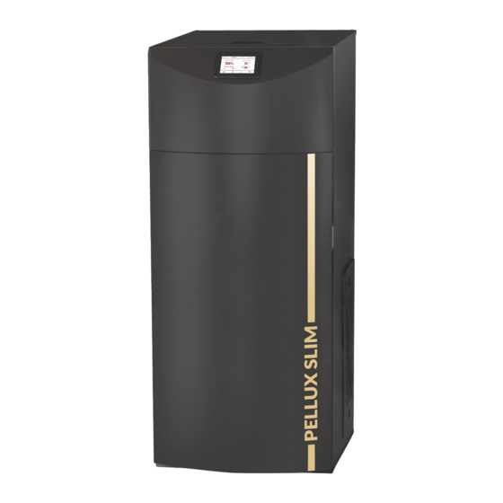
- Page 1 03-08-2021 INSTALLATION & OPERATING MANUAL 30609 Pellet boiler PELLUX SLIM 12 PELLUX SLIM 18 21-01-2019...
- Page 2 In summer, the boiler must remain connected to the power supply - to reduce the risk of condensation in the panel. To stop the boiler operation, turn off the heating circuits on the regulator. NIBE-BIAWAR sp. z o.o. 15-703 Białystok, Al. Jana Pawła II 57 PELLUX SLIM 12 069235 1/N/PE 230V, 50Hz, 10A IP21 3,5-12,1 kW...
-
Page 3: Table Of Contents
Activation of the summer feature ___________16 8 Other Boiler Settings ________________17 Fuel Level Configuration _________________17 Information ___________________________17 Manual Control ________________________17 Cooperation with the room panel __________17 Cooperation with the internet module _______18 PELLUX SLIM 12 List of contents | PELLUX SLIM 18... -
Page 4: General
With the enhanced electronic control, you can control many parameters of the unit, adjusting it to different installation conditions and individual needs. This Manual applies to the Pellux Slim 12 boiler and the Pellux Slim 18 boiler. ADVICE Certificates confirming the possession of the 5th class... -
Page 5: Symbols
• Ventilation ducts should be made of non-flamma- IMPORTANT ble materials. PELLUX Slim boiler may only be installed by compe- tent and qualified personnel, in accordance with ap- plicable regulations, standards and manufacturer’s CAUTION recommendations. Failure to follow these instructions... -
Page 6: Installation
4 Installation Intended Use System diagram The Pellux Slim heating boiler is designed for heating UWAGA This is a schematic representation only. The actual single and multi-family residential buildings or public diagram of the system should be developed by an in- buildings. -
Page 7: Control Panel
Tip: The fuel level can also be seen in the room panel. PELLUX SLIM 12 Chapter 5 | Control Panel PELLUX SLIM 18... -
Page 8: Start-Up And Shutdown
• The pellets are supplied to the burner at a spe- cifi c dose (default for Pellux Slim 12 boiler is 100g, for Pellux Slim 18 - 140g ) • Igniter is activated... -
Page 9: Operating Modes
100 % to 30 % with the eration time, airflow time and feeder operation time. omission of 50 %. PELLUX SLIM 12 Chapter 5 | Control Panel PELLUX SLIM 18... -
Page 10: Supervision
After the lapse of the monitoring ti me, the control- ler enters into the BURNING OFF mode, unless the boiler temperature has dropped earlier, and the boiler returns into the OPERATION mode automatically. Chapter 5 | Control Panel PELLUX SLIM 12 PELLUX SLIM 18... -
Page 11: Menu Główne - Użytkownika
This menu contains setpoints of the controlled heating circuits. These circuits are controlled by electric actuator operating the mixing valve. Lower temperature in relation to the boiler temperature can be achieved in these circuits. * Mixer settings PELLUX SLIM 12 Chapter 5 | Control Panel PELLUX SLIM 18... - Page 12 Main menu 12:00 Only authorized persons should use the service settings. Service Settings * -unavailable if the appropriate sensor or additional module is not connected or the parameter is hidden. Chapter 5 | Control Panel PELLUX SLIM 12 PELLUX SLIM 18...
-
Page 13: Heating
PELLUX SLIM 12 Chapter 6 | Heating PELLUX SLIM 18... -
Page 14: Weather-Based Control
Chapter 6 | Heating PELLUX SLIM 12 PELLUX SLIM 18... -
Page 15: Selecting The Heat Source For The Mixer
Service → Buff er settings→ Start heating instal- lation When selecting the BOILER, the CH pump mixer will start after reaching the parameter: Service → CH and HUW settings → Pump Temp. start PELLUX SLIM 12 Chapter 6 | Heating PELLUX SLIM 18... -
Page 16: Hot Utility Water
HUW Settings →HUW preset temperature The HUW tank hysteresis Below the temperature: HUW preset temperature – HUW Tank Hysteresis the HUW pump starts in order to fill the HUW tank. PELLUX SLIM 12 Chapter 7 | Hot Utility Water PELLUX SLIM 18... -
Page 17: Other Boiler Settings
Fill the fuel dispenser to the level corresponding to 100% load and set the parameter: Boiler Settings → Fuel Level → Fuel Level Cali- bration → Fuel Level 100 % PELLUX SLIM 12 Chapter 8 | Other Boiler Settings PELLUX SLIM 18... -
Page 18: Cooperation With The Internet Module
Performing these activities is the responsibility of the bo- iler user and is not part of the warranty. For more information, see Cleaning on page 48. Chapter 9 | Maintenance and Troubleshooting PELLUX SLIM 12 PELLUX SLIM 18... -
Page 19: Causes Of Failure And Remedy
Boiler’s temperature limiter has tripped, this can occur during transportation • Circulating pump set to lower speed or switched • Too large fl ow of the hot utility water PELLUX SLIM 12 Chapter 9 | Maintenance and Troubleshooting PELLUX SLIM 18... -
Page 20: General Information For Installers
The Pellux Slim boiler has a round fl ue gas outlet with a diameter of 80. The outlet should be tightly connec- ted (eg with a connection made of appropriately thick sheet metal) to the chimney. - Page 21 2.5 m. CAUTION Before connecting the boiler, flush the system to re- move small debris that can damage the boiler or pump. PELLUX SLIM 12 Chapter 10 | General Information for Installers PELLUX SLIM 18...
-
Page 22: Connection To The System
11 Connection to the System The diagrams below show the connection of the PELLUX boiler with a hot utility water exchanger, in an open system with heating circuit and a domestic hot water circuit. Pellux Slim connected to a heating circuit with a four-way valve and a DHW exchanger. -
Page 23: Electrical Connections
RPM RPM WS HDW PL 11 12 13 5 6 7 14 15 17 18 19 20 21 230V~ The diagram below shows connection of the additional B module. PELLUX SLIM 12 Chapter 12 | Electrical connections PELLUX SLIM 18... - Page 24 Chapter 12 | Electrical connections PELLUX SLIM 12 PELLUX SLIM 18...
-
Page 25: Connection
CAUTION Connection may only be performed with power supply disconnected and only by an individual appropriately authorized to do it. PELLUX SLIM 12 Chapter 12 | Electrical connections PELLUX SLIM 18... - Page 26 2, 3, 4 pump OFF (without switching the burner OFF), 1572,0 1573,1 1574,2 set the Pump Switch OFF by the Thermostat to YES. Service Settings → Mixer 1 Settings → Pump Switch OFF by the Thermostat Chapter 12 | Electrical connections PELLUX SLIM 12 PELLUX SLIM 18...
- Page 27 PELLUX SLIM 12 Chapter 12 | Electrical connections PELLUX SLIM 18...
- Page 28 Maximum pressure exceeded instruction manual for these devices. AL10 Exhaust fan damaged AL11 Grate blocked AL12 Vacuum sensor damaged AL13 Max. temp. of fumes exceeded AL14 Fumes sensor damage Chapter 12 | Electrical connections PELLUX SLIM 12 PELLUX SLIM 18...
-
Page 29: Boiler Settings
The menu includes parameters such as: Limi- Output modulation tation of the max. boiler power, Feeding correc- Limitation of the max. boiler power 12kW tion or fan correction. Feeding correction Fan correction PELLUX SLIM 12 Chapter 13 | Boiler settings PELLUX SLIM 18... - Page 30 HUW Schedule circulation pump. The HUW circulation pump ena- bles the quick appearance of hot water in parts of the building distant from the boiler room. Chapter 13 | Boiler settings PELLUX SLIM 12 PELLUX SLIM 18...
- Page 31 HUW cont. hysteresis HUW disinfection On / Off Night time decrease HUW On/Off Decrease Schedule * unavailable, unless the corresponding sensor or additional module is connected or the parameter is hidden PELLUX SLIM 12 Chapter 13 | Boiler settings PELLUX SLIM 18...
- Page 32 Delete device associations CHIMNEY SWEEP mode CHIMNEY SWEEP mode On/Off Boiler output setting Worktime * unavailable, unless the corresponding sensor or additional module is connected or the parameter is hidden Chapter 13 | Boiler settings PELLUX SLIM 12 PELLUX SLIM 18...
-
Page 33: Service
Igniter pre-heating time Firing-up time Feeder time in firing-up Incandescence time Blow-in fan output INCANDESCENCE Fumes delta Blow-in output in fire-up Vacuum in fire-up Blowin output after fire-up Vacuum after fire-up PELLUX SLIM 12 Chapter 14 | Service PELLUX SLIM 18... - Page 34 Min. boiler temperature Max. boiler temperature Boiler cooling temperature Reserve boiler Alarms * unavailable, unless the corresponding sensor or additional module is connected or the parameter is hidden ** RPM or % Chapter 14 | Service PELLUX SLIM 12 PELLUX SLIM 18...
- Page 35 Valve closing Buffer settings Buffer support Loading start temperature Loading end temperature Start heat installation * unavailable, unless the corresponding sensor or additional module is connected or the parameter is hidden PELLUX SLIM 12 Chapter 14 | Service PELLUX SLIM 18...
- Page 36 Display orientation Normal / Inverted Restore defaults settings Restore defaults settings Acceptance / Cancellation * unavailable, unless the corresponding sensor or additional module is connected or the parameter is hidden Chapter 14 | Service PELLUX SLIM 12 PELLUX SLIM 18...
-
Page 37: Service Settings
1150r/min Vacuum 50% 10Pa The intermediate boiler power 6 kW (2.2sek.) Blow-in fan output 30% Minimum boiler output 3 kW (1.1sek.) 1000r/min Vacuum 30% Blow-in fan output 100% 1400 r/min PELLUX SLIM 12 Chapter 14 | Service PELLUX SLIM 18... - Page 38 Fuel dose during firing up. Concerns first testing firing up. Next tests fuel dose Fuel dose is reduced (by default: Pellux Slim 12 - 100 g, Pellux Slim 18 - 140 g). Time of verification whether the furnace has already been fired up (change in Ignition test time exhaust gas temperature by a delta 2.5...
- Page 39 The time is counted down after the exhaust gas temperature drops below the No fuel exhaust temperature parameter. Treshold flame no fuel Flue gas temperature value below which no flame is detected. PELLUX SLIM 12 Chapter 14 | Service PELLUX SLIM 18...
- Page 40 Parameter C FuzzyLogic temperature. It is not recommended to change these parameters if the regulation speed and the stability of keeping the temperature setpoint are at the expected level. Chapter 14 | Service PELLUX SLIM 12 PELLUX SLIM 18...
- Page 41 YES (the boiler pump operates in a short circuit ‘boiler/heat exchang- er’ and is not switched OFF by e.g. SUMMER feature or HUW priority.) • NO (the pump operates as usual.) PELLUX SLIM 12 Chapter 14 | Service PELLUX SLIM 18...
- Page 42 Chapter 14 | Service PELLUX SLIM 12 PELLUX SLIM 18...
- Page 43 Options available: • Normal • Inverted (screen inverted by 180 RESTORE DEFAULTS Description SETTINGS Restore defaults settings Acknowledgment of this setting restores all default settings of the control unit parameters. PELLUX SLIM 12 Chapter 14 | Service PELLUX SLIM 18...
-
Page 44: Software Update
Anti-Frost Protection If the boiler temperature drops below 5 C, the boiler pump will be activated forcing the boiler water circu- lation. The burner is activated when the temperature rises. Chapter 14 | Service PELLUX SLIM 12 PELLUX SLIM 18... -
Page 45: Connecting Accessories
CT4 controlled circuit temp sensor (mixer #3) mixer room thermostat Mixer actuator Mixer pump HUW circulating pump Voltage output Relay (5-6V, max 80mA) Reserve boiler Alarm signaling ecoMAX controller, A module, G3 socket PELLUX SLIM 12 Chapter 14 | Service PELLUX SLIM 18... - Page 46 20.9% + -0.1%. After measuring the oxygen value, the fan turns off and the lambda sensor goes into stop mode. The whole calibration process takes about 8 minutes. The boiler can be restarted. ecoLambda 2B. Chapter 14 | Service PELLUX SLIM 12 PELLUX SLIM 18...
-
Page 47: Boiler (Stb) And Feeder
STB may be reset only when the boiler has cooled down. If the boiler temperature is still high, STB will not reset. This applies to boiler STB and feeder tem- perature limiter. PELLUX SLIM 12 Chapter 14 | Service PELLUX SLIM 18... -
Page 48: Cleaning
• remove the ash from the burner and the boiler, • mount the burner housing. Funnel Grate Burner shelf chamber Chapter 14 | Service PELLUX SLIM 12 PELLUX SLIM 18... -
Page 49: Periodic Cleaning Of The Boiler
4 screws and remove the chamber cover, CAUTION • clean the chamber with a vacuum cleaner. Before a longer break in using the boiler, empty the pellet storage bin to avoid pellet scaling. PELLUX SLIM 12 Chapter 14 | Service PELLUX SLIM 18... - Page 50 • unscrew the handle, then unscrew 4 bolts securing the mechanism housing and remove it (pos. 1), Place that need to be cleaned Chapter 14 | Service PELLUX SLIM 12 PELLUX SLIM 18...
-
Page 51: Alarms
Sensor failure. Damage to the sensor cable. Max. temp. of fumes The exhaust gas temperature has exceeded the maximum value. exceeded Fumes sensor damage Sensor failure. Damage to the sensor cable. PELLUX SLIM 12 Chapter 14 | Service PELLUX SLIM 18... -
Page 52: Wiring Diagrams
15 Wiring Diagrams Boiler Chapter 15 | Wiring Diagrams PELLUX SLIM 12 PELLUX SLIM 18... -
Page 53: Location Of Components
16 Location of Components PELLUX SLIM 12 Chapter 16 | Location of Components PELLUX SLIM 18... - Page 54 11. Convection ducts cleaning mechanism. device). 12. Flue gas turbulators. XL3 Blowdown connection. 13. Convection ducts. FL1 Safety valve with drain line. 14. Pellet storage bin. 15. Transport pipe. Chapter 16 | Location of Components PELLUX SLIM 12 PELLUX SLIM 18...
-
Page 55: Electrical Components
1. Boiler primary module. 2. Feeder temperature limiter. 3. Boiler temperature limiter. 4. Pressure sensor in the combustion chamber. 5. Main ON/OFF switch. 6. Exhaust gas temperature sensor. PELLUX SLIM 12 Chapter 16 | Location of Components PELLUX SLIM 18... -
Page 56: Dimensions
17 Dimensions Dimensions Symbol Pellux Slim 12 Pellux Slim 18 600 mm 1464 mm 865 mm 910 mm 149 mm 73 mm 192 mm 342 mm Connection Diameter number Pellux Slim 12-18 G1” G 3/4” ø 80 mm G1” G1”... -
Page 57: Technical Specifications
19 Technical Specifications IP 21 Parameter Pellux Slim 12 Pellux Slim 18 Boiler class Rated power 12,17 kW 18,46 kW Net weight 320 kg 320 kg Pellet storage bin capacity 100 kg 100 kg Water capacity 38 l 38 l... - Page 60 KARTA GWARANCYJNA KOTŁY C.O. NA PELET NIBE-BIAWAR Sp. z o.o. al. Jana Pawła II 57 15-703 Białystok tel. 85 662 84 90, fax 85 662 84 09 sekretariat@biawar.com.pl www.pellux.com.pl www.biawar.com.pl...
Need help?
Do you have a question about the PELLUX SLIM 12 and is the answer not in the manual?
Questions and answers