
Related Manuals for ICI Caldaie ASX200

Summary of Contents for ICI Caldaie ASX200
- Page 1 Superheated water heat generator INSTALLATION, USE AND MAINTENANCE MANUAL ASX_200_3000_en_00 - 10/2019 Cooke Industries - Phone: +64 9 579 2185 Email: sales@cookeindustries.co.nz Web: www.cookeindustries.co.nz...
- Page 2 INDEX General information Product receipt Handling Introduction Film removal Range Installation room Compliance Positioning Warnings Room ventilation Prohibitions System cleaning Hazards Hydraulic connections Prohibitions Flue exhaust Hazards Electrical connections Identification Front door opening Appliance description Door opening reversal (to the right) DESCRIPTION OF THE EQUIPMENT Front door adjustment OPERATING PRINCIPLE OF THE HEATING SYSTEM...
- Page 3 This manual refers to boilers with “standard accessories”. For boilers that “do not require continuous monitoring” by the operator refer to the specific technical manual. RANGE CODE MODEL 5 bar 12 bar ASX200 86290200 86390200 ASX300 86290300 86390300 ASX400 86290400...
- Page 4 In case of damage or loss, request a copy from Technical Assistance Service ICI CALDAIE S.p.A. . This body must be intended for the use it was expressly designed for. The manufacturer will be exempted from any liability, contractual and extra-contractual, for any injury/damage caused to people, animals, or property due to the failure to perform maintenance and/or scheduled periodic checks and improper uses.
- Page 5 – Dangers due to water leaks . Disconnect the boiler from the electrical power supply, close the water supply and promptly contact the Technical Assistance Service Authorised ICI CALDAIE S.p.A. or professionally qualified personnel. – Routine and extraordinary maintenance must be entrusted to professionally qualified personnel with the purpose of promptly detecting any damage to the generator's pressurised body and the safety and control accessories.
- Page 6 DANGER – Danger deriving from the fuel. Sensing the presence of fuel in the thermal power plant, it is appropriate to follow the precautions below to avoid the risk of explosions and fires: - do not smoke or cause sparks - do not turn on lights or electrical devices in general (mobile phones) - open doors and windows - close the fuel shut-off valve normally placed outside the thermal power plant...
-
Page 7: Appliance Description
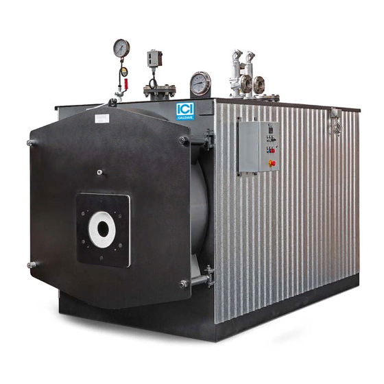
APPLIANCE DESCRIPTION Monobloc reverse flame fire tube super-heated water boilers with fully wet-bottom furnace. Built with tested quality steel according to regulations in force and welded with automatic submerged arc methods. Suitable for liquid and gaseous fuels. Complete with regulation and safety accessories for automatic operation. The single front door is thermally insulated with refractory materials and is mounted on adjustable hinges, easily opened without having to remove the burner;... -
Page 8: Technical Data
TECHNICAL DATA ASX 200 ÷ 800(5 BAR) DESCRIPTION u.m. Nominal power Thermal capacity 1032 Efficiency at 100% (N.C.V.) 90,31 90,18 90,12 90,08 90,18 90,12 Hydraulic pressure drop mbar Rated pressure Total capacity 1095 1245 1535 Total weight 1400 1600 1850 2200 2200 2600... - Page 9 ASX 200 ÷ 800(12 BAR) DESCRIPTION u.m. Nominal power Thermal capacity 1032 90,31 90,18 90,12 90,08 90,18 90,12 Efficiency at 100% (N.C.V.) Hydraulic pressure drop mbar Rated pressure Total capacity 1080 1250 1515 Total weight 1540 1580 2035 2925 3245 3600 Electric supply Volt ~...
-
Page 10: Dimensions And Connections
DIMENSIONS AND CONNECTIONS 1 Electrical panel 10 Burner application plate N1 Boiler flow line 2 Min/max pressure switches 11 Inspection hatch N2 Boiler return line 3 Thermometer 12 Safety valves N3 Safety valve drain 4 Pressure gauge 13 Rear smoke chamber N4 Boiler drain 5 Thermoregulator and display 14 Chimney fitting... - Page 11 ASX 1000 ÷ 3000(5-12BAR) Dimensions u.m. 1000 1200 1500 1750 2000 2500 3000 2170 2260 2490 2430 2610 2730 2880 1580 1840 1870 1870 1980 2100 2190 1720 1820 2030 2030 2120 2260 2360 1000 1200 1200 1200 1380 1430 1500 1650 1740...
- Page 12 BURNERS The burners that can be installed on the ASX boilers must be CE marked according to European Directives: – Gas Directive 2009/142/EC – Electromagnetic Compatibility Directive 2014/30/EU – Low Voltage Directive 2014/35/EU – Machinery Directive 2006/42/EC (for liquid fuel burners) Since the optimal operation of the boiler depends on the correct selection of the burner and its adjustment, find below some points to take into account: –...
-
Page 13: User Obligations
PAPERWORK These generators, supplied in single-block, are CE marked according to the Directive 2014/68/EU "PED". The documentation supplied with the generator is: – declaration of conformity of the whole – use and maintenance manual (always housed in the electrical panel) –... -
Page 14: Pressure Gauge
COMPONENTS The superheated water boilers ASX feature a series of components that can be divided into: – Safety components (safety valves, safety pressure switch, safety thermostat). – Indicator components (temperature indicator, pressure gauge, flame warning light). – Adjustment components (Thermostat). In the descriptions below, accessories are divided based on the values they control. -
Page 15: Safety Valves
SAFETY VALVES The safety valves are able to maintain the pressure in the generator to the design pressure (save temporary peaks of 10% max of the max PS of the whole) even if all other pressure control devices (pressure switches and transmitters) are out of use. These valves are regulated by specific national and international standards, therefore they are sized, tested, installed and maintained in compliance with the applicable regulations and the contents of this manual. -
Page 16: Safety Thermostat
VALVE MAINTENANCE The valve is a very delicate mechanism, so the system operator must check its efficiency. If necessary, contact a technician authorised by the manufacturer. It is good practice for the safety valves installed to protect the plant: – to be operated (once a week) with system pressurised, by activating the manual lifting lever of the shutter –... -
Page 17: Control Panel
CONTROL PANEL The boiler ASX is equipped with a control panel for the management and control of the equipment. The type of panel is chosen based on the boiler configuration. For more details refer to the layout and wiring diagram provided with the installed panel. - Page 18 THERMOREGULATION AND MESSAGE DISPLAY Thermoregulator front Instructions:1 =2nd stage of burner on (enabled to work)2 =Burner on (enabled to work) Display of flow temperature measured or indication of the variable during the thermoregulator parametrization phase (HSET - SP - AL2 - HAL2) Display of the burner AL2 (ON-OFF variable) or of the sets of variables during the thermoregulator parametrization phase (HSET - SP - AL2 - HAL2) Enter key, its pressure allows accessing variable parametrization and if you push it again it scrolls the sequence of variables(HSET...
- Page 19 Thermoregulator parametrization example Push the enter key (4), field 2 to display the HSET variable and field 3 to display the variable parametrization (example: working temperature hysteresis 2°C); to modify the variable push the up and down keys (5). Attention: HSET hysteresis affects both above and below the Set Point; this means that, for example, if the desired Set Point temperature is 110°C and hysteresis 2°C, the control at 2nd stage burner will be interrupted at 112°C and activated again at 108°C.
-
Page 20: Installation
Installation PRODUCT RECEIPT The ASX generators are supplied complete with accessories. The combustion chamber contains: – turbulator unit to be inserted in the smoke pipes during installation – thermoceramic material to be inserted in the gap between burner mouthpiece and door insulation The control panel contains the following documentation: –... -
Page 21: Film Removal
HANDLING ATTENTION Pay the utmost care during handling and use the Personal Protective Equipment requested by the prevailing regulations. The ASX generator must be handled using means adequate to the size and weight of the appliance, using the provided lifting eyebolts. -
Page 22: Installation Room
INSTALLATION ROOM POSITIONING The ASX boiler installation room must be for exclusive use, meet the Technical Standards and Legislation in force and equipped with adequately sized ventilation openings. It is recommended to position the boiler, if possible, lifted from the floor to minimise dust extraction by the burner fan. For information only, below is some useful information: –... -
Page 23: System Cleaning
The air must be filtered with a 25 μm mesh. IMPORTANT ICI CALDAIE S.p.A. is not liable for any harm to people, animals or property damage caused by errors in the choice of components or in the construction of the plant. -
Page 24: Electrical Connections
Technical Standards and the local and national Legislation. IMPORTANT Connect the generator to an efficient earthing system. ICI CALDAIE S.p.A. is not liable for any damage caused by the lack of earthing and failure to comply with the wiring diagram. - Page 25 FRONT DOOR OPENING The door is adjusted in the factory with standard opening to the left (Sx) and hinges on the right (Dx). DOOR OPENING REVERSAL (TO THE RIGHT) IMPORTANT Door opening inversion is possible ONLY for models from ASX 200 to ASX 1000. ASX 200÷1200 ASX 200÷1200 ASX 1500÷3000...
- Page 26 DANGER When cross-changing ferrules, always make sure that the other two ferrules are fastened, so that they hold the door. Proceed as follows to reverse the opening direction of the door: – loosen drilled ring nut (1) and socket ring nut (8) –...
-
Page 27: Front Door Adjustment
– following a cross pattern, swap the socket ring nut of a hinge (8) with the opposite drilled one (1), – fix the conical washer (4) to the door with nut (2) – repeat the whole sequence for the other ring nuts Check the correct adjustment of the tie-rods and hinges ensuring that, during closure, the seal gasket is evenly pressed in the centre on the whole circumference. - Page 28 HORIZONTAL ADJUSTMENT Close the door using the lever and check that there is equal distance on both sides, between the stop plate and the band. If this is not the case: – with the door ajar, loosen the locking nuts (6) of the hinge units –...
-
Page 29: Burner Assembly
Technical Standards and the local and national Legislation. IMPORTANT Connect the generator to an efficient earthing system. ICI CALDAIE S.p.A. is not liable for any damage caused by the lack of earthing and failure to comply with the wiring diagram. -
Page 30: Water Characteristics
WATER CHARACTERISTICS The values in the following tables are extracted from tables 5.1 and 5.2 in EN 12953-10 (requirements concerning the quality of water supply and the water in the generator). Even for generators that are not covered by the aforementioned provision it is however necessary to adopt at least the indicated limits and however, to refer to the specialised companies that manage selecting the type of treatment to be carried out on the basis of a thorough analysis of the water available. - Page 31 NOTE These values are valid assuming the presence of a thermal deaerator. In the absence of the deaerator, it is appropriate, however, to raise the temperature of the water contained in the tank to at least 80°C to reduce the content of dissolved gas (O and CO It is, in any case, appropriate to use chemical conditioning to de-oxygenate the water supply completely and to minimise the corrosive CO...
-
Page 32: Preliminary Checks
PRELIMINARY CHECKS IMPORTANT – Before start-up, open the door and insert the turbulators completely inside the front ends of the smoke pipes, taking care to push them inside by at least 100 mm. – Check that all fittings are fully tightened. –... - Page 33 COMMISSIONING Start up the boiler as follows: 1) Power the boiler control panel on the general switch. 2) Make sure that the pressurization system has efficiently set the system to the minimum pressure. 3) The boiler must be operated at reduced power (max 50%) until reaching the water operating temperature in order to avoid thermal shocks and thermal expansions between the various parts of the body.During the start-up phase, it is recommended to limit the flow rate of the water passing through the boiler in order to reduce the condensation phenomenon and the consequent acid corrosion of the parts in contact with flue gases.The critical dew point temperature is approximately 57°C with methane gas...
-
Page 34: Checks After Commissioning
CHECKS AFTER COMMISSIONING The system must be operated properly in order, on the one hand, to ensure an optimal combustion with reduced emissions into the atmosphere of carbon oxide, unburnt hydrocarbons and soot and, on the other, to prevent material damage and injuries to persons. - Page 35 The pressurisation must fall within the values indicated in the table of the technical data. IMPORTANT The temperature difference between flow and return must not exceed 30°C in order to avoid thermal shocks to the boiler. The return temperature from the system must be higher than 50°C with operation with methane gas or LPG and 40°C with operation with fuel oil or naphtha to protect the boiler against corrosion due to the acid condensate of flue gases.
-
Page 36: Routine Maintenance
Maintenance Periodic maintenance is an obligation required by the safety Legislation and duration of the appliance, and it must only be entrusted to professionally qualified personnel. The frequency of the operations is shown in the specific paragraph. IMPORTANT Before performing any maintenance or cleaning: –... - Page 37 PERIODIC VERIFICATIONS The frequency of verifications is shown in the table. It MUST be strictly observed . Observation and 1 day 1 week 1 month 3 months 6 months 12 months tests Safety valves T(1) Shut-off valves T(4) Protection devices, T(2) T(5) T(12)
-
Page 38: Extraordinary Maintenance
METHODS FOR CHECKING THE SAFETY DEVICES CHECK OF THE SAFETY PRESSURE SWITCH The safety pressure switch calibration must be at least 0.5 bar below the calibration of the safety valves. To check the correct intervention of the safety pressure switch, it is necessary to increase the calibration of the adjustment pressure switch(es) and ensure the switch-off of the burner and activation of the block on the boiler electrical panel by visually following the indication given by the pressure gauge. -
Page 39: Protecting The Environment
PROTECTING THE ENVIRONMENT Protection and respect for the environment is a fundamental principle for ICI CALDAIE S.p.A. . The quality of products, lower costs and protection of the environment are of equal importance for the company. ICI CALDAIE S.p.A. , also through ISO 14001 certification, strictly adheres to European laws and standards for the protection and preservation of the environment. - Page 40 Residual Risk Management EXCESSIVE STEAM PRESSURE – Make sure the safety valves properly open at the design pressure. – It is necessary to check the correct activation of the shut-off pressure switch that eliminates the cause of pressure increase by stopping the burner.
- Page 41 CORROSION – Carry out water analysis at the necessary time intervals (refer to user's manual). – Perform water treatments in order to bring the characteristic values back within the limits specified in the use and maintenance manual. – Keep water at a temperature above 60 °C to facilitate deoxygenation. PRESENCE OF SLUDGE –...
-
Page 42: Minimum Temperature
HOT SURFACES – Avoid contact with generator uninsulated parts during operation. Should adjustment or check activities be carried out during operation, the operators must wear suitable protective equipment (gloves, shoes and thermal coverall). – Protection with suitable clothing (PPE in compliance with the prevailing laws). –... - Page 43 TAMPERING – The accessories must not be tampered with (safety valve, pressure switches, electric panel or level probes). The generator must be operated by qualified personnel. In case of accident due to tampering, the manufacturer accepts no liability. DECOMMISSIONING – Periodical check by the operator, as stated in the Technical Manual, and appliance decommissioning, if necessary. –...
- Page 44 Once registered, authenticate your e-mail address by clicking on the link that will be sent by e-mail to the provided inbox. An additional e-mail will then be received with the credentials to access all services specifically developed by ICI CALDAIE S.p.A.
- Page 45 Notes Notes Cooke Industries - Phone: +64 9 579 2185 Email: sales@cookeindustries.co.nz Web: www.cookeindustries.co.nz...
- Page 46 Notes Cooke Industries - Phone: +64 9 579 2185 Email: sales@cookeindustries.co.nz Web: www.cookeindustries.co.nz...
- Page 47 Notes Cooke Industries - Phone: +64 9 579 2185 Email: sales@cookeindustries.co.nz Web: www.cookeindustries.co.nz...
- Page 48 ICI CALDAIE SpA 37059 Fraz. Campagnola di Zevio ( Verona) Italy Via G. Pascoli 38 Phone: +39 0458738511 Fax:+39 0458731148 info@icicaldaie.com www.icicaldaie.com Cooke Industries - Phone: +64 9 579 2185 Email: sales@cookeindustries.co.nz Web: www.cookeindustries.co.nz...
Need help?
Do you have a question about the ASX200 and is the answer not in the manual?
Questions and answers