VESDA Sensepoint XCL Installation Manual
Hide thumbs
Also See for Sensepoint XCL:
- Installation manual (49 pages) ,
- Quick start manual (10 pages)

Related Manuals for VESDA Sensepoint XCL


Summary of Contents for VESDA Sensepoint XCL
- Page 1 VESDA Sensepoint XCL Aspirated Gas Detector Installation Manual October 2018 Document no: 33889_00 Part no: 30931...
- Page 3 VESDA by Xtralis VESDA Sensepoint XCL Installation Manual Disclaimer The contents of this document is provided on an “as is” basis. No representation or warranty (either express or implied) is made as to the completeness, accuracy or reliability of the contents of this document. The manufacturer reserves the right to change designs or specifications without obligation and without further notice.
- Page 4 VESDA Sensepoint XCL Installation Manual VESDA by Xtralis Document Conventions The following typographic conventions are used in this document: Convention Description Bold Used to denote: emphasis Used for names of menus, menu options, toolbar buttons Italics Used to denote: references to other parts of this document or other documents.
- Page 5 VESDA-E VEA smoke detector. The manual is intended for the operator involved in the design and maintenance of the VESDA Sensepoint XCL gas detector and must have a good understanding of the working principles of the VESDA-E VEA smoke detector (Product Guide).
- Page 6 VESDA Sensepoint XCL Installation Manual VESDA by Xtralis This page is intentionally left blank. www.xtralis.com...
-
Page 7: Table Of Contents
Securing the Back Box to a Wall Cable Connections Ground Connections 2.10 Securing the Detector Module to the Back Box 2.11 Connecting VESDA Sensepoint XCL to VESDA-E VEA Commissioning Commissioning the Detector Status Indicator Maintenance Using the Control Buttons Maintenance Status Indicator... -
Page 8: Introduction
Analog output: VESDA Sensepoint XCL features current loop output, supporting signals in the range 0 to 22 mA. Typically this interface is referred to as 4 to 20 mA. -
Page 9: Detectable Gases
VESDA Sensepoint XCL Installation Manual VESDA by Xtralis Detectable Gases VESDA Sensepoint XCL is available for the detection of Carbon Monoxide gas. Detector Versions The 4-way terminal block(s) provide connection for both the gas detector output and the power supply. -
Page 10: Relay Output
VESDA by Xtralis VESDA Sensepoint XCL Installation Manual Relay Output Legend Relay No. 1 Relay No. 2 Where fitted, there are two configurable relays which can be used to control or signal to external devices, such as audible and visual alarms and other control systems. -
Page 11: Specifications
Height 59 mm (2.3 in) Weight 500 g (1.1 lb) Power Supply VESDA Sensepoint XCL requires an isolated power supply unit that is certified by a national or international standard, such as UL. Specification Value † Nominal DC input voltage 24 V DC ‡... - Page 12 Specification Value Inner diameter 5 mm ( 0.19 in) Outer diameter 6 mm (0.24 in) † VESDA Sensepoint XCL conforms to IP65, Type 4 (in accordance with NEMA 250) making it suitable for use in Pollution Degree 3 environments 33889_00...
-
Page 13: Installation
To minimize the risk of electrostatic charge, provision shall be made for adequate grounding and equipment shall be installed in such a manner so that accidental discharge shall not occur. When VESDA Sensepoint XCL reaches the end of its life, it should be disposed of in accordance with local regulations. -
Page 14: Detector Module
VESDA Sensepoint XCL Installation Manual VESDA by Xtralis V+ detector V+ controller V detector V controller Controller Field Cable (L) V- detector V- controller The maximum loop resistance (R ) in the field cable is calculated as follows: loop max = (V −... -
Page 15: Wiring Of Ma Output Versions
VESDA by Xtralis VESDA Sensepoint XCL Installation Manual Wiring of mA Output Versions Power Connection When connecting to DC power, make sure that the polarity is correct. If an external power source is used, ensure that terminal 4 “Common” is used to connect the power and controller grounds together. - Page 16 VESDA Sensepoint XCL Installation Manual VESDA by Xtralis Note: The load resistance of the controller must be between 33 Ω and 250 Ω. When the mA output is not being used, a 33 Ω, 0.125 W load resistor should be connected between terminal 3 (4–20 mA) and terminal 2 (0 V) for source mode or terminal 1 (+24 V DC) for sink mode.
-
Page 17: Wiring Of Modbus Output Versions
VESDA Sensepoint XCL Installation Manual Wiring of Modbus Output Versions Modbus Connection For Modbus versions, up to 32 VESDA Sensepoint XCL detectors can be connected in a daisy chain arrangement as shown in the diagram below. Note: Where possible, spur or ‘T’ connections should be avoided. Always keep the spur connection as short as possible. -
Page 18: Securing The Back Box To A Wall
VESDA Sensepoint XCL Installation Manual VESDA by Xtralis Securing the Back Box to a Wall CAUTION: Before starting installation, make sure that the system controller or external power source is switched off. 1. There are four screw positions in the rear of the back box for mounting purposes. Punch the required screw positions or drill using a 4 mm drill. -
Page 19: Cable Connections
VESDA by Xtralis VESDA Sensepoint XCL Installation Manual Cable Connections 1. Fit suitable cable glands appropriate to the application and type of cable being utilized to the opened cable entries. 2. Feed the cable through the cable gland. 3. Turn over the detector module and locate the terminal blocks on the back. Remove the terminal blocks by pulling them toward the center of the module. -
Page 20: Ground Connections
VESDA Sensepoint XCL Installation Manual VESDA by Xtralis 5. Replace the terminal blocks in their correct positions. Ground Connections Effective grounding is crucial to ensure stable Modbus communications and to limit the effects of radio frequency interference. Ground points are provided inside the back box. In order to prevent false readings or alarms as a result of ground loops, ensure that the shield of all cables are grounded at a single point, preferably at the controller. -
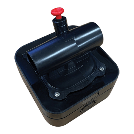
Page 21: 2.10 Securing The Detector Module To The Back Box
2. Where used, tighten the sealing nut of the cable gland to secure the cable. 3. Use the Calibration/Flow Cap that has been factory matched to the VESDA Sensepoint XCL. Check the serial number label on the Calibration/Flow Cap against that of the detector. -
Page 22: 2.11 Connecting Vesda Sensepoint Xcl To Vesda-E Vea
VESDA Sensepoint XCL Installation Manual VESDA by Xtralis 2.11 Connecting VESDA Sensepoint XCL to VESDA-E VEA 1. Insert 50mm length of supplied adaptor flexible tubes to interface the inlet and outlet ports of the Calibration/Flow Cap to the VEA tubes. Ensure the flexible tubes are inserted over the full length of the nozzles. -
Page 23: Commissioning
Commissioning Note: The VESDA Sensepoint XCL gas detector is supplied from the factory pre-calibrated. However, it is strongly recommended that the detector response is checked and if necessary, re-calibrated before placing it into service. Refer to Calibration for details on the correct calibration procedure. -
Page 24: Status Indicator
6. Remove power and refit the detector module to the back box. 7. Apply power. The VESDA Sensepoint XCL will enter a warm-up mode during which time the status indicator will be steady yellow and the output (mA version) will be held in an inhibited state. - Page 25 VESDA by Xtralis VESDA Sensepoint XCL Installation Manual Inhibited: The indicator is on steady yellow when the user has placed the detector into the inhibit state for maintenance or repair. Alarm: The indicator flashes red when the gas concentration is beyond the alarm-level threshold.
-
Page 26: Maintenance
Using the Control Buttons It is possible to perform basic maintenance functions on the VESDA Sensepoint XCL gas detector without the use of the mobile app. This is achieved through the use of two control buttons inside the detector. Familiarize yourself fully on the operation of these buttons before attempting to use them. -
Page 27: Calibration
4. Connect another tube to the other gassing port, and place the end of this tube in a position so that gas can exhaust safely away from the work area and other personnel. 5. Connect the smart device to the VESDA Sensepoint XCL via Bluetooth. Tap the Calibration button, select Calibration and follow the on-screen instructions. - Page 28 Otherwise, an alarm may occur. 8. Use the cancel function to return to normal monitoring mode. 9. Re-connect the flexible tubes to VESDA Sensepoint XCL Calibration/Flow Cap and connect to the VESDA-E VEA tubes. 10. For an initial VEA installation (i.e. out-of-box VEA), NORMALIZE the VEA smoke detector. For an existing VEA installation, RESET the VEA detector.
-
Page 29: Bump Test / Line Integrity Test
4. Connect smartphone to the VESDA Sensepoint XCL detector via Bluetooth. 5. Place the VESDA Sensepoint XCL detector in inhibit mode by using the inhibit control on the mobile app. 6. Attach 100m (328ft) 4mm ID (0.16in ID) tube or equivalent reduced diameter tube length upstream the VESDA Sensepoint XCL Calibration/Flow Cap. -
Page 30: Replacing The Sensor
Attempting to use non-genuine sensors could result in malfunction of the product. CAUTION: Do not replace the sensor without first a) removing power to the VESDA Sensepoint XCL or b) placing the sensor into the sensor maintenance mode. 1. Disable the VEA smoke detector, disconnect both flexible tubes from the Calibration/Flow Cap nozzles and remove Cap. -
Page 31: Resetting Alarms And Faults
VESDA Sensepoint XCL Installation Manual VESDA by Xtralis 5. Ensuring that the sensor pins are correctly aligned, insert a new sensor into the sensor socket. CAUTION: Do not force the sensor into the socket, otherwise it may be damaged. 6. Press and hold the UP button for 2 seconds to activate warm-up mode. In this mode, the output continues to be held in its inhibit state. -
Page 32: Mobile App
VESDA Sensepoint XCL Installation Manual Mobile App Use the Sensepoint app to allow your smart device to connect to VESDA Sensepoint XCL. This mobile app makes it much easier to configure and maintain VESDA Sensepoint XCL detectors. The general procedure of using the mobile app is as follows: 1. -
Page 33: A Appendices
VESDA by Xtralis VESDA Sensepoint XCL Installation Manual A Appendices Detector Parameters Bluetooth Version: Detector User Selectable Default User Selectable Cal Default Cal Response Time t90 (s) – Resolution Accuracy (ppm or % of applied gas Steps Point Standalone which is the greater) -
Page 34: Troubleshooting
Fault 13 Calibration Overdue Calibrate the unit. Ordering Information 1. Detectors Part Number Description XCL-VEA-CO-RLMA VESDA Sensepoint XCL CO 300ppm 4-20mA Relay for VEA XCL-VEA-CO-RLMB VESDA Sensepoint XCL CO 300ppm Modbus Relay for VEA 2. Accessories www.xtralis.com... -
Page 35: Warranty
Gasket Warranty Xtralis warrants the VESDA Sensepoint XCL gas detector against defective parts and workmanship. This warranty does not cover consumable, batteries, fuses, normal wear and tear, or damage caused by accident, abuse, improper installation, unauthorized use, modification or repair, ambient environment, poisons, contaminants or abnormal operating conditions. -
Page 36: Safety Information For Wireless Devices
2. This device must accept any interference, including interference that may cause undesired operation of the device 3. R&TTE Compliance Hereby, Honeywell Analytics Asia Pacific Co., Ltd. declares that this gas detector, Sensepoint XCL, is in compliance with the essential requirements and other relevant provisions of Directive 1999/5/EC. www.xtralis.com...
Need help?
Do you have a question about the Sensepoint XCL and is the answer not in the manual?
Questions and answers