Table of Contents
Advertisement
Quick Links
Advertisement
Table of Contents

Subscribe to Our Youtube Channel
Related Manuals for IceTech PR350H

Summary of Contents for IceTech PR350H
- Page 1 User’s manual PR350H User’s Manual Technical file...
- Page 2 User’s manual PR350H User’s Manual...
-
Page 3: Table Of Contents
Original Version: Page: 1 of 20 IceTech PR350H Date: 2017.07.03 Industrivej 62 User’s manual Init: DK-6740 Bramming Denmark CONTENT GENERAL INFORMATION SYSTEM DESCRIPTION • Functional description • System identification • Supplier responsible for the equipment TECHNICAL DATA TECHNICAL FACTS OF FROZEN CO SAFETY REGULATIONS •... -
Page 4: Icetech Pr350H
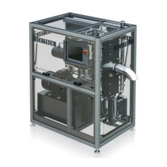
Denmark GENERAL INFORMATION The IceMaker PR350H presents a state of the art dry ice pelletizer packed with features for easier operation, swift production shifts and high capacity. The IceMaker PR350H produces high quality dry ice pellets from stroke one. This is secured by the closed chamber technology which also ensures fast production shifts and an extremely short start up time. -
Page 5: System Description
Functional description The main function of IceTech PR350H is to produce dry ice pellets from liquid carbon dioxide. This is performed by a sequence of operations executed by the Beckhoff IPC. The main steps in a normal production are as following and refer to PI diagram P296-1-14201-B for IceTech PR350H: 1. -
Page 6: System Identification
Original Version: Page: 4 of 20 IceTech PR350H Date: 2017.07.03 Industrivej 62 User’s manual Init: DK-6740 Bramming Denmark System identification System is marked with: Supplier responsible for the equipment Cold Jet ApS Industrivej 62 DK-6740 Bramming Denmark Phone: +45 75 56 15 00 Fax: +45 75 56 15 09 Homepage: www.coldjet.com, www.icetechworld.com... -
Page 7: Technical Data
Original Version: Page: 5 of 20 IceTech PR350H Date: 2017.07.03 Industrivej 62 User’s manual Init: DK-6740 Bramming Denmark TECHNICAL DATA Rated Output: kg/h: up to 350 lbs/h: up to 772 of high quality dry ice pellets, depending on the extruder plate applied... -
Page 8: Technical Facts Of Frozen Co
Original Version: Page: 6 of 20 IceTech PR350H Date: 2017.07.03 Industrivej 62 User’s manual Init: DK-6740 Bramming Denmark TECHNICAL FACTS OF FROZEN CO Dry ice is frozen carbon dioxide (CO ). It is much denser and colder than traditional ice. Dry ice is -79°C (-109.3°F). -
Page 9: Safety Regulations
The owner of the machine shall make sure that the operator, who is to work with the IceTech PR350H, fully understands the importance of complying with the SAFETY REGULATIONS described on the following pages as well as those placed on the machine, and the importance of carefully studying the contents of the manual. -
Page 10: Static Electricity
Original Version: Page: 8 of 20 IceTech PR350H Date: 2017.07.03 Industrivej 62 User’s manual Init: DK-6740 Bramming Denmark Therefore, please note the following: 1. Low CO concentrations (3-5%) cause headaches and fast breathing. 2. CO concentrations of (7-10%) cause headaches and nausea and may result in unconsciousness. -
Page 11: Pinch Point Hazard
Original Version: Page: 9 of 20 IceTech PR350H Date: 2017.07.03 Industrivej 62 User’s manual Init: DK-6740 Bramming Denmark Pinch Point Hazard If the plexiglass covers in front of the extruder plates are removed, the operator will be exposed to pinch point hazard. -
Page 12: Safety Operation
DK-6740 Bramming Denmark SAFETY OPERATION Emergency stop All equipment is connected to the general emergency system for IceTech PR350H. When an emergency-stop device is activated, all components located in the emergency zone will be disconnected from their power source. Machine safety There are machine safety measures in the following areas: •... -
Page 13: Machine Structure
Original Version: Page: 11 of 20 IceTech PR350H Date: 2017.07.03 Industrivej 62 User’s manual Init: DK-6740 Bramming Denmark MACHINE STRUCTURE PR350H 1 Pellets outlet sprout 2 Hydraulic station 3 Main hydraulic cylinder 4 Touch panel 5 Extruder plate cylinder 6 Extruder plate changer... -
Page 14: Machine Operation Start-Up
Original Version: Page: 12 of 20 IceTech PR350H Date: 2017.07.03 Industrivej 62 User’s manual Init: DK-6740 Bramming Denmark MACHINE OPERATION START-UP PR350H Make sure that the CO , power supply and exhaust CO pipe are connected. Open the ball valves on the mounting kit. - Page 15 Make sure the correct extruder plates are installed in the extruder plate changer and select which extruder plate to use on the “Extruder plate changer” page. To start up the IceTech PR350H, select the “Automatic mode” and press the “Start” button.
-
Page 16: Machine Controls
Original Version: Page: 14 of 20 IceTech PR350H Date: 2017.07.03 Industrivej 62 User’s manual Init: DK-6740 Bramming Denmark MACHINE CONTROLS PR350H 1 Start up page This page can be activated from any page by pressing the “Home button” in the lower right hand corner. - Page 17 Original Version: Page: 15 of 20 IceTech PR350H Date: 2017.07.03 Industrivej 62 User’s manual Init: DK-6740 Bramming Denmark 3 Mode select By activating the “mode select” button, it is possible to choose between automatic mode and single mode. The default selection is automatic mode, which must be selected for production.
- Page 18 Original Version: Page: 16 of 20 IceTech PR350H Date: 2017.07.03 Industrivej 62 User’s manual Init: DK-6740 Bramming Denmark 5 Process values By pressing the “gauge” button the “process values” page is activated. The page contains a 2-column display of real time process values (PV). The corresponding “Set Values”...
-
Page 19: Liquid Co 2 Leakage
Cold Jet technician or by the owner’s qualified personnel who has been trained by Cold Jet in the repair and maintenance of IceTech dry ice blasting and dry ice production machines and accessories. -
Page 20: Instruction - Unpacking And Preparations Before Installation
• The ambient temperature must be min. +5°C (+41°F). How to Lift / Transport the IceMaker IceMaker PR350H: Drawing no. A1 • The IceMaker is supplied with thread holes for lifting eyes. Always use lifting eyes to lift the IceMaker. - Page 21 Init: DK-6740 Bramming Denmark DRAWING No. A1 Correct Handling of IceMaker PR350H Min. load capacity of forklift truck: 1150kg/2535 lbs Min. fork length: 1.0 m The IceMaker is supplied with thread holes for lifting eyes. Always use lifting eyes to lift the...
-
Page 22: Version: Page: 1 Of
Original Version: Page: 20 of 20 IceTech PR350H Date: 2017.07.03 Industrivej 62 User’s manual Init: DK-6740 Bramming Denmark DRAWING No. A2... - Page 23 Original [EN] We as the manufacturer: Cold Jet, ApS Industrivej 62 DK - 6740 Bramming Hereby declares that the following product: PR350H Pelletizer Product Designation: Type/Serial no.: Is in compliance with the following European directives: Directive 2006/42/EC [Machinery Directive] Directive 2014/30/EU...
- Page 24 User’s manual PR350H Technical file...
- Page 25 Technical file PR350H Table for mechanical maintenance Procedures for maintenance and repair Alarm list P&I Diagram Assembly drawings Installation layout drawings Wiring diagram Datasheets Accessories...
- Page 26 Technical file PR350H Table for mechanical maintenance...
- Page 27 Get a particle analysis of the oil if in doubt about the contamination degree. IceTech recommend the owner to have a spare part package in stock, so repairs can be made quickly and with a very little loss of production time.
- Page 28 This table includes all the service intervals from 0 hours to 20000 hours. For each service interval there will be listed which procedures is necessary to perform and the IceTech article no. for spare parts package. Table for mechanical maintenance Pelletizer PR350H Service interval Hours/Month Procedure no.
- Page 29 Technical file PR350H Procedures for maintenance and repair...
- Page 30 9 Calibration of Ø160/Ø50 hydraulic cylinders. 37 – 42 10 Replacement of Danfoss EV3/EV15 valves. 43 – 44 11 Replacement of extruderpiston. 45 – 50 12 Changing Air filter. 51 – 54 13 Changing hydraulic pump Rexroth. 55 – 56 14 Changing hydraulic oil hydraulic station. 57 – 58 15 16 17 18 www.icetechworld.com | IceTech Dry Ice Technology Rev 1 Page 1...
- Page 31 Procedures for maintenance and repair www.icetechworld.com | IceTech Dry Ice Technology Rev 1 Page 2...
- Page 32 Procedures for maintenance and repair Procedure no. 1 Replacement of liquid CO2 filter + gasket Procedure for changing CO2 filter and gasket on PR750H and PR350H During this operation it’s important to activate the emergency stop button! www.icetechworld.com | IceTech Dry Ice Technology...
- Page 33 4 Notice! It is very important to be careful and not get any dust or dirt into the filter housing under this operation; this could block the Danfoss solenoid valves. www.icetechworld.com | IceTech Dry Ice Technology Rev 1 Page 4...
- Page 34 Procedures for maintenance and repair Procedure no. 1 Replacement of liquid CO2 filter + gasket 3 4 2 1 www.icetechworld.com | IceTech Dry Ice Technology Rev 1 Page 5...
- Page 35 Procedures for maintenance and repair www.icetechworld.com | IceTech Dry Ice Technology Rev 1 Page 6...
- Page 36 Procedures for maintenance and repair Procedure no. 2 Replacement of degassingfilter + gasket Procedure for changing degassing filters on PR750H and PR350H During this operation it’s important to activate the emergency stop button! www.icetechworld.com | IceTech Dry Ice Technology Rev 1...
- Page 37 It’s important that the screws are not switched as they will block and damage the extruder. At production startup, it’s important to check if the degassing sleeves are tightened correctly. www.icetechworld.com | IceTech Dry Ice Technology Rev 1 Page 8...
- Page 38 Procedures for maintenance and repair Procedure no. 3 Replacement of pistonrings Procedure for changing the piston ring on PR750H and PR350H During this operation it’s important to activate the emergency stop button! www.icetechworld.com | IceTech Dry Ice Technology Rev 1...
- Page 39 So it’s important to put a strap around it to avoid any unnecessary hazard. The extruder plate changer can be fixated as displayed below. 1 2 3 4 www.icetechworld.com | IceTech Dry Ice Technology Rev 1 Page 10...
- Page 40 Remove the filter on one side of the extruder cylinder to gain access to the piston by loosening the 8 screws and pull the filter housing [5], rubber gasket [6], filter and filter gasket out, and you have access inside the extruder chamber. www.icetechworld.com | IceTech Dry Ice Technology Rev 1 Page 11...
- Page 41 Loosen the 8 screws [11] and remove screws, washers [12] and brackets [10] for piston. The piston [13] can now be driven out through the front of the barrel. www.icetechworld.com | IceTech Dry Ice Technology Rev 1 Page 12...
- Page 42 Reassemble with the hydraulic piston shaft. Screws have to be lubricated and then tightened equally and with torque 21.4 Nm. BEFORE STARTING PRODUCTION THE HYDRAULIC MOTION SHOULD BE CHECKED IN SINGLE MODE! www.icetechworld.com | IceTech Dry Ice Technology Rev 1 Page 13...
- Page 43 Replacement of pistonrings Operating in single mode control 1 Select single mode 2 Enter Manual operation 3 Start the hyd. pump 4 Move the pistons using the arrow buttons The operation is complete. At production startup, it’s important to check if the degassing sleeves are tightened correctly. www.icetechworld.com | IceTech Dry Ice Technology Rev 1 Page 14...
- Page 44 Procedure for changing hydraulic return oil filter on PR750H and PR350H 1. Screw 2. Housing top plate 3. Pressure gauge 4. Return oil filter housing During this operation it’s important to activate the emergency stop button! www.icetechworld.com | IceTech Dry Ice Technology Rev 1 Page 15...
- Page 45 Operating in single mode control 1 Select single mode 2 Enter Manual operation 4 Move the pistons using 3 Start the hyd. pump the arrow buttons Check that there are no leaks on the hydraulic station. The operation is complete. www.icetechworld.com | IceTech Dry Ice Technology Rev 1 Page 16...
- Page 46 During this operation it’s important to activate the emergency stop button! Important For operators safety the hydraulic cylinder has to be disconnected from the hydraulic system before dismounting. www.icetechworld.com | IceTech Dry Ice Technology Rev 1 Page 17...
- Page 47 The cylinder top pos. 2 is screwed back in the cylinder tube pos. 3. 14. The hydraulic cylinder has to be checked for any leaks and is then ready to be mounted on the machine again. www.icetechworld.com | IceTech Dry Ice Technology Rev 1 Page 18...
- Page 48 4 Move the pistons using 3 Start the hyd. pump the arrow buttons Check once again that there are no leaks both connections and piston rod seals. The operation is complete. www.icetechworld.com | IceTech Dry Ice Technology Rev 1 Page 19...
- Page 49 Procedures for maintenance and repair Procedure no. 5 Replacement of gaskets in Ø160 hydraulic cylinder. www.icetechworld.com | IceTech Dry Ice Technology Rev 1 Page 20...
- Page 50 Replacement of wear inserts in die changer. Procedure for changing the wear inserts in die changer on PR750H and PR350H During this operation it’s important to activate the emergency stop button! www.icetechworld.com | IceTech Dry Ice Technology Rev 1 Page 21...
- Page 51 Step (9) and step (10) now the 8 screws which are holding the wear inserts can be dismounted and the wear inserts can be changed. Assemble the die changer again, going backwards in the procedure steps. www.icetechworld.com | IceTech Dry Ice Technology Rev 1 Page 22...
- Page 52 1 Select single mode 2 Enter Manual operation 4 Move the pistons using 3 Start the hyd. pump the arrow buttons It is important to check that both extruder cylinder and die changer cylinder is operating correctly, before production start up. The operation is complete. www.icetechworld.com | IceTech Dry Ice Technology Rev 1 Page 23...
- Page 53 Procedures for maintenance and repair Procedure no. 6 Replacement of wear inserts in die changer. www.icetechworld.com | IceTech Dry Ice Technology Rev 1 Page 24...
- Page 54 Procedures for maintenance and repair Procedure no. 7 Replacement of Ø160 hydraulic cylinder. Procedure for changing the hydraulic cylinder on PR750H and PR350H During this operation it’s important to activate the emergency stop button! www.icetechworld.com | IceTech Dry Ice Technology...
- Page 55 So it’s important to put a strap around it to avoid any unnecessary hazard. The extruder plate changer can be fixated as displayed below. 1 2 3 4 www.icetechworld.com | IceTech Dry Ice Technology Rev 1 Page 26...
- Page 56 8 pcs. screws and pull the filter housing [5], rubber gasket [6], filter and filter gasket out, and you have access inside the extruder chamber. www.icetechworld.com | IceTech Dry Ice Technology Rev 1 Page 27...
- Page 57 Loosen the 8 screws and remove screws, washers and brackets for piston. [13] The piston can now be driven out through the front of the barrel. www.icetechworld.com | IceTech Dry Ice Technology Rev 1 Page 28...
- Page 58 Remove and plug the hydraulic hoses [14]. The plug [15] on the linear encoder is removed. The hydraulic cylinder is removed by loosening the 4 nuts [16]. MAKE SURE TO SUPPORT THE HYDRAULIC CYLINDER! www.icetechworld.com | IceTech Dry Ice Technology Rev 1 Page 29...
- Page 59 A spring loaded gasket [18] is located between the hydraulic cylinder and the center plate. This should be removed before the cylinder is lifted out of the machine. www.icetechworld.com | IceTech Dry Ice Technology Rev 1 Page 30...
- Page 60 571 Nm. To check if the hydraulic cylinder is installed correctly, drive the piston all the way forward. With little force it should be possible to turn the piston in this position. Mount the hoses and plugs. Refill the hydraulic oil if necessary. Before installing the extruder plate, it’s important to check if the extruder barrel is clear on the inside, and that there is nothing preventing the piston from operating. www.icetechworld.com | IceTech Dry Ice Technology Rev 1 Page 31...
- Page 61 Operating in single mode control 1 Select single mode 2 Enter Manual operation 3 Start the hyd. pump 4 Move the pistons using the arrow buttons The operation is complete. At production startup, it’s important to check if the degassing sleeves are tightened correctly. www.icetechworld.com | IceTech Dry Ice Technology Rev 1 Page 32...
- Page 62 Procedures for maintenance and repair Procedure no. 8 Replacement of Ø50 hydraulic cylinder. Procedure for changing the hydraulic cylinder Ø50 on PR750H and PR350H During this operation it’s important to activate the emergency stop button! www.icetechworld.com | IceTech Dry Ice Technology Rev 1 Page 33...
- Page 63 Step (5) Loosen the contra nut. Step (6) Hold this nut while loosening contra nut. Assemble the hydraulic cylinder and die changer again, going backwards in the procedure steps. www.icetechworld.com | IceTech Dry Ice Technology Rev 1 Page 34...
- Page 64 4 Move the pistons using 3 Start the hyd. pump the arrow buttons It is important to check that both extruder cylinder and die changer cylinder is operating correctly, before production start up. The operation is complete. www.icetechworld.com | IceTech Dry Ice Technology Rev 1 Page 35...
- Page 65 Procedures for maintenance and repair Procedure no. 8 Replacement of Ø50 hydraulic cylinder. www.icetechworld.com | IceTech Dry Ice Technology Rev 1 Page 36...
- Page 66 Click on the calibration device The left LED is green 1. Activate buttons Press button 1 or 2 for at least 3 seconds Release button The right LED is green www.icetechworld.com | IceTech Dry Ice Technology Rev 1 Page 37...
- Page 67 Bring the hydraulic cylinder piston to new null point Right LED is red and left LED is off Press button 1 for at least 2 seconds Both LED flashes green in alternation www.icetechworld.com | IceTech Dry Ice Technology Rev 1 Page 38...
- Page 68 The left LED is green The buttons are now deactivated Note: If this step is not carried out, the automatic deactivation will become active after 10 minutes where the buttons are inactive www.icetechworld.com | IceTech Dry Ice Technology Rev 1 Page 39...
- Page 69 Press button 1 or 2 for at least 3 seconds Release button The right LED is green 6.3 Activate buttons Immediately after press both buttons in, hold for at least 3 seconds The left LED flashes green www.icetechworld.com | IceTech Dry Ice Technology Rev 1 Page 40...
- Page 70 LED indicators Picture of step by step 7. Reset Immediately after press both buttons in, hold for at least 6 seconds The left and right LED flashes green and red simultaneously. www.icetechworld.com | IceTech Dry Ice Technology Rev 1 Page 41...
- Page 71 Procedures for maintenance and repair Procedure no. 9 Calibration of Ø160/Ø50 hydraulic cylinders. www.icetechworld.com | IceTech Dry Ice Technology Rev 1 Page 42...
- Page 72 Procedures for maintenance and repair Procedure no. 10 Replacement of Danfoss EV3/EV15 Valves. Procedure for changing Danfoss EV3 and EV15 valves + solenoids on PR750H and PR350H During this operation it’s important to activate the emergency stop button! www.icetechworld.com | IceTech Dry Ice Technology Rev 1...
- Page 73 Notice! It is very important to be careful and not get any dust or dirt into the valve or pipes under this operation; this could block the Danfoss solenoid valves. www.icetechworld.com | IceTech Dry Ice Technology Rev 1 Page 44...
- Page 74 Procedures for maintenance and repair Procedure no. 11 Replacement of extruderpiston. Procedure for changing the extruder piston on PR750H and PR350H During this operation it’s important to activate the emergency stop button! www.icetechworld.com | IceTech Dry Ice Technology Rev 1...
- Page 75 So it’s important to put a strap around it to avoid any unnecessary hazard. The extruder plate changer can be fixated as displayed below. 1 2 3 4 www.icetechworld.com | IceTech Dry Ice Technology Rev 1 Page 46...
- Page 76 Remove the filter on one side of the extruder cylinder to gain access to the piston by loosening the 8 screws and pull the filter housing [5], rubber gasket [6], filter filter gasket out, and you have access inside the extruder chamber. www.icetechworld.com | IceTech Dry Ice Technology Rev 1 Page 47...
- Page 77 [11] and remove screws, washers [12] and brackets [10] for piston. The piston [13] can now be driven out through the front of the barrel. www.icetechworld.com | IceTech Dry Ice Technology Rev 1 Page 48...
- Page 78 BEFORE STARTING PRODUCTION THE HYDRAULIC MOTION SHOULD BE CHECKED IN SINGLE MODE! 1 www.icetechworld.com | IceTech Dry Ice Technology Rev 1 Page 49...
- Page 79 3 Start the hyd. pump 4 Move the pistons using the arrow buttons The operation is complete. At production startup, it’s important to check if the degassing sleeves are tightened correctly. www.icetechworld.com | IceTech Dry Ice Technology Rev 1 Page 50...
- Page 80 Procedures for maintenance and repair Procedure no. 12 Changing Air filter. Procedure for changing the air filter on PR750H and PR350H 2. Air filter 3. Silica gel 1. Air filter unit 4. Plug hole During this operation it’s important to activate the emergency stop button! ...
- Page 81 Procedure step by step Unscrew the air filter unit pos. 1 from plug holes pos. 4 in hydraulic station. Unscrew the yellow air filter pos. 2. www.icetechworld.com | IceTech Dry Ice Technology Rev 1 Page 52...
- Page 82 Replace the air filter pad pos. 5. Mount a new air filter pos. 2. Assemble the air filter unit and screw it into the plug holes pos. 4 again. www.icetechworld.com | IceTech Dry Ice Technology Rev 1 Page 53...
- Page 83 1 Select single mode 2 Enter Manual operation 4 Move the pistons using 3 Start the hyd. pump the arrow buttons Check that there are no leaks on the hydraulic station. The operation is complete. www.icetechworld.com | IceTech Dry Ice Technology Rev 1 Page 54...
- Page 84 During this operation it’s important to activate the emergency stop button! Changing or repairing the hydraulic pump. This operation is only to be carried out by IceTech service technician or by an IceTech approved company such as Bosch / Rexroth.
- Page 85 4 Move the pistons using 3 Start the hyd. pump the arrow buttons Check once again that there are no leaks both connections and piston rod seals. The operation is complete. www.icetechworld.com | IceTech Dry Ice Technology Rev 1 Page 56...
- Page 86 Procedures for maintenance and repair Procedure no. 14 Changing hydraulic oil hydraulic station. Procedure for changing oil on hydraulic station on PR750H and PR350H 2. Hydraulic tank 3. Cover plate 1. Ball valve During this operation it’s important to activate the emergency stop button! ...
- Page 87 DTE MOBIL FM 46 IceTech Art.Nr.4F0221. Approved for food manufacturing” in the hydraulic tank. Notice: If there are no demand for oil approved for food manufacturing, this oil can be used instead DTE MOBIL 10 Excel 46 IceTech Art.Nr.4F0220. See hydraulic oil specifications in section 8 datasheets. Recommended oil volume: PR750H 260 Litres DTE MOBIL FM 46 or DTE MOBIL 10 Excel 46.
- Page 88 IN SINGLE MODE! Operating in single mode control 1 Select single mode 2 Enter Manual operation 3 Start the hyd. pump 4 Move the pistons using the arrow buttons Check that there are no leaks on the hydraulic station. The operation is complete. www.icetechworld.com | IceTech Dry Ice Technology Rev 1 Page 59...
- Page 89 Technical file PR350H Alarm list...
- Page 90 Original Version: Page: 1 of 3 IceTech PR350H Industrivej 62 DK-6740 Bramming Date: 01.02.16 Alarm List Denmark Init: ALARM LIST Using the alarm list and diagrams in the appendix for solving problems with the Pelletizer PR750H. When errors appear comparing and indentify it in the table below. Then go to the appendix at the page which is listed in the table. Here there will be a flow diagram which will guide through a troubleshooting sequence.
- Page 91 Original Version: Page: 2 of 3 IceTech PR350H Industrivej 62 DK-6740 Bramming Date: 01.02.16 Alarm List Denmark Init: Max. oil temperature exceeded. Oil level too low / level sensor activated. Extruder 1 min. temperature for degassing exceeded. (A500) Extruder 2 min. temperature for degassing exceeded. (B500) Extruder 1 min.
- Page 92 Original Version: Page: 3 of 3 IceTech PR350H Industrivej 62 DK-6740 Bramming Date: 01.02.16 Alarm List Denmark Init: Error Weight Error No container on the Weight Error FF plug below Min. Extruder 1 Error FF plug above Max. Extruder 1 Error FF plug below Min.
- Page 94 Troubleshooting Troubleshooting errors on Pelletizer PR750H and PR350H. Solving alarm tag name ID 1 Purge limit 1 not reached. Alarm code no. 400. Check if the valve is frozen. => tough up the valve. Yes, one of the valves Reset and restart Check the valve for mechanical failure.
- Page 95 Troubleshooting errors on Pelletizer PR750H and PR350H. 1. There could be a mechanical problem Tag name ID 2+3+4+5+6+7+8+9 inside the extruder cylinder or hydraulic Yes, there is a mechanical problem or Repair or replace the component Reset and restart Extruder 1 or 2 max. time cylinder.
- Page 96 Troubleshooting errors on Pelletizer PR750H and PR350H. 1. There could be a build up of dry ice Tag name ID inside the extruder cylinder behind the 10+11+12+13+14+15+16+17 Yes, the piston ring or piston i Replace the component which are Reset and restart extruder piston.
- Page 97 Troubleshooting errors on Pelletizer PR750H and PR350H. 1. The temperature of the hydraulic oil is to Refill with the necesarry amount of Reset and restart Yes, the oil level is low. high above 70°C (158°F). oil. the Pelletizer. The error cannot be reset until the temperature has fallen below 50°C (122°F).
- Page 98 Troubleshooting errors on Pelletizer PR750H and PR350H. Refill with the necesarry amount of Reset and restart Yes, the oil level is low. oil. the Pelletizer. 1. The level sensor is activated. Check oil level. No, there is no problems. Go to point 2...
- Page 99 Troubleshooting errors on Pelletizer PR750H and PR350H. 1. There could be CO particles in the Yes, the degassing filter is worn, Replace the component which are Reset and restart degassing sytem. blocked or damaged. broken or worn out. the Pelletizer.
- Page 100 Troubleshooting errors on Pelletizer PR750H and PR350H. Check if the valve is frozen. => tough up the valve. Yes, one of the valves are Check the valve for mechanical failure. => Reset and restart not working replace the valve. the Pelletizer.
- Page 101 Troubleshooting errors on Pelletizer PR750H and PR350H. Yes, the error is still there Contact IceTech for tecnical support. 1. There is an error in the hydraulic motor. Tag name ID 29 Error motor relay. Try to reset and restart the system No, there is no error anymore.
- Page 102 Troubleshooting errors on Pelletizer PR750H and PR350H. Yes, the error is still there Contact IceTech for tecnical support. 1. There is an internal error in the system. Tag name ID 30 internal error. Try to reset and restart the system No, there is no error anymore.
- Page 103 Troubleshooting errors on Pelletizer PR750H and PR350H. Reset and restart Yes, the tank is empty. Fill the tank. 1. This could be due to pressure drop in the the Pelletizer. installation. Check that there is sufficient CO in the tank.
- Page 104 Troubleshooting errors on Pelletizer PR750H and PR350H. Yes, the filters is blocked, dirty, worn Replace the component which is Reset and restart 1. The pressure is to high inside the or damaged. blocked, dirty, worn or damaged. the Pelletizer. extruder.
- Page 105 Troubleshooting errors on Pelletizer PR750H and PR350H. Yes, the emergency stop button is Reset and restart Release emergency stop button. activated. the Pelletizer. 1. Check if the emergency stop button is activated. No, there is no problems. Go to point 2 Tag name ID 33 Emergency stop activated.
- Page 106 Troubleshooting errors on Pelletizer PR750H and PR350H. Try to recalibrate the transducer it might be nesecarry to reset before the calibration can be carried out. See procedure 9. Yes, the Balluff transducer is not Reset and restart The wire connection and plug 1.
- Page 107 Troubleshooting errors on Pelletizer PR750H and PR350H. Tag name ID 36+37 Yes, one of the extruderplates is not Make the selection of the Reset and restart selected. extruderplates. the Pelletizer. Error extruder plate 1 not 1. The extruderplate 1 or 2 has not been selected.
- Page 108 Troubleshooting errors on Pelletizer PR750H and PR350H. Reset and restart Yes, the tank is empty. Fill the tank. 1. This could be due to pressure drop in the the Pelletizer. installation. Check that there is sufficient CO in the tank.
- Page 109 Troubleshooting errors on Pelletizer PR750H and PR350H. Reset and restart the Turn off the weight and turn it on again. Pelletizer. Tag name ID 40 The signal from the weight is not correct or mayby disconnected. Error weight. Contact IceTech technical No, the weight is in order and connected.
- Page 110 Troubleshooting errors on Pelletizer PR750H and PR350H. Yes, there is no container on the Place an empty container on the Reset and restart weight. weight. the Pelletizer. Tag name ID 41 Check if there is a container on the weight.
- Page 111 Troubleshooting errors on Pelletizer PR750H and PR350H. Reset and restart Yes, the tank is empty. Fill the tank. 1. This could be due to pressure drop in the the Pelletizer. installation. Check that there is sufficient CO in the tank.
- Page 112 Troubleshooting errors on Pelletizer PR750H and PR350H. Reset and restart Yes, the tank is empty. Fill the tank. 1. This could be due to pressure drop in the the Pelletizer. installation. Check that there is sufficient CO in the tank.
- Page 113 Technical file PR350H P&I Diagram...
- Page 114 PROPRIETARY AND CONFIDENTIAL: THE INFORMATION CONTAINED IN THIS DRAWING IS THE SOLE PROPERTY OF ICETECH A/S. ANY REPRODUCTION IN PART OR AS A WHOLE WITHOUT THE WRITTEN PERMISSION OF ICETECH A/S IS PROHIBITED. T3 Gas P2 Gas =V01 =W01 =G01...
- Page 115 18/08/2015 1 of 2 Tag-numbers for PR350H V3 P296-1-14201-B IceTech ASPECT ASPECT DESCRIPTION TAG DESCRIPTION Varenummer Beskrivelse Digital In Digital Out Analog In Analog Out Datablad relative links Dry ice cleaning unit DI=V01 Filter unit DI=V01 Filter unit Filter for filter unit...
- Page 116 18/08/2015 2 of 2 Tag-numbers for PR350H V3 P296-1-14201-B DI=G1-Q3 Extruder plate 1 heating -TT2 Temperature transmitter 1 501979 Temperatur transmitter 2 ledet PT100 PT100 DI=G1-Q3 Extruder plate 1 heating Cartridge heater 1 501978 Cartridge heater 2 pcs 230V 350W...
- Page 117 Technical file PR350H Assembly drawings...
- Page 118 PROPRIETARY AND CONFIDENTIAL: THE INFORMATION CONTAINED IN THIS DRAWING IS THE SOLE PROPERTY OF ICETECH A/S. ANY REPRODUCTION IN PART OR AS A WHOLE WITHOUT THE WRITTEN PERMISSION OF ICETECH A/S IS PROHIBITED. Note! Position 8 - Part number 501855 - Electric Motor UL. 7 1/2 HP 3x220V AC 60 Hz 1770 rpm 11 kW ITEM NO.
- Page 119 PROPRIETARY AND CONFIDENTIAL: THE INFORMATION CONTAINED IN THIS DRAWING IS THE SOLE PROPERTY OF ICETECH A/S. ANY REPRODUCTION IN PART OR AS A WHOLE WITHOUT THE WRITTEN PERMISSION OF ICETECH A/S IS PROHIBITED. 1500 1000 1000 SECTION B-B SECTION A-A...
- Page 120 PROPRIETARY AND CONFIDENTIAL: THE INFORMATION CONTAINED IN THIS DRAWING IS THE SOLE PROPERTY OF ICETECH A/S. ANY REPRODUCTION IN PART OR AS A WHOLE WITHOUT THE WRITTEN PERMISSION OF ICETECH A/S IS PROHIBITED. PART NUMBER Description QTY. 510168 Frame assembly, PR350H...
- Page 121 PROPRIETARY AND CONFIDENTIAL: THE INFORMATION CONTAINED IN THIS DRAWING IS THE SOLE PROPERTY OF ICETECH A/S. ANY REPRODUCTION IN PART OR AS A WHOLE WITHOUT THE WRITTEN PERMISSION OF ICETECH A/S IS PROHIBITED. ITEM NO. PART NUMBER Description QTY. 501320...
- Page 122 PROPRIETARY AND CONFIDENTIAL: THE INFORMATION CONTAINED IN THIS DRAWING IS THE SOLE PROPERTY OF ICETECH A/S. ANY REPRODUCTION IN PART OR AS A WHOLE WITHOUT THE WRITTEN PERMISSION OF ICETECH A/S IS PROHIBITED. Option: 502972 1 set of parts for heating set (a process unit)
- Page 123 PROPRIETARY AND CONFIDENTIAL: THE INFORMATION CONTAINED IN THIS DRAWING IS THE SOLE PROPERTY OF ICETECH A/S. ANY REPRODUCTION IN PART OR AS A WHOLE WITHOUT THE WRITTEN PERMISSION OF ICETECH A/S IS PROHIBITED. ITEM NO. PART NUMBER DESCRIPTION QTY. 501420 Gasket f.
- Page 124 PROPRIETARY AND CONFIDENTIAL: THE INFORMATION CONTAINED IN THIS DRAWING IS THE SOLE PROPERTY OF ICETECH A/S. ANY REPRODUCTION IN PART OR AS A WHOLE WITHOUT THE WRITTEN PERMISSION OF ICETECH A/S IS PROHIBITED. ITEM NO. PART NUMBER DESCRIPTION QTY. 503029...
- Page 125 PROPRIETARY AND CONFIDENTIAL: THE INFORMATION CONTAINED IN THIS DRAWING IS THE SOLE PROPERTY OF ICETECH A/S. ANY REPRODUCTION IN PART OR AS A WHOLE WITHOUT THE WRITTEN PERMISSION OF ICETECH A/S IS PROHIBITED. 101016 Option 103005-1 501776 Option 501881 ITEM NO.
- Page 126 PROPRIETARY AND CONFIDENTIAL: THE INFORMATION CONTAINED IN THIS DRAWING IS THE SOLE PROPERTY OF ICETECH A/S. ANY REPRODUCTION IN PART OR AS A WHOLE WITHOUT THE WRITTEN PERMISSION OF ICETECH A/S IS PROHIBITED. ITEM NO. PART NUMBER DESCRIPTION QTY. 501433...
- Page 127 PROPRIETARY AND CONFIDENTIAL: THE INFORMATION CONTAINED IN THIS DRAWING IS THE SOLE PROPERTY OF ICETECH A/S. ANY REPRODUCTION IN PART OR AS A WHOLE WITHOUT THE WRITTEN PERMISSION OF ICETECH A/S IS PROHIBITED. ITEM NO. PART NUMBER DESCRIPTION QTY. 502276...
- Page 128 PROPRIETARY AND CONFIDENTIAL: THE INFORMATION CONTAINED IN THIS DRAWING IS THE SOLE PROPERTY OF ICETECH A/S. ANY REPRODUCTION IN PART OR AS A WHOLE WITHOUT THE WRITTEN PERMISSION OF ICETECH A/S IS PROHIBITED. ITEM NO. PART NUMBER Description QTY. 101221 Safety valve, 1/4", 27,6 bar...
- Page 129 PROPRIETARY AND CONFIDENTIAL: THE INFORMATION CONTAINED IN THIS DRAWING IS THE SOLE PROPERTY OF ICETECH A/S. ANY REPRODUCTION IN PART OR AS A WHOLE WITHOUT THE WRITTEN PERMISSION OF ICETECH A/S IS PROHIBITED. ITEM NO. PART NUMBER DESCRIPTION QTY. 501955 Hydr.
- Page 130 Technical file PR350H Installation layout drawings...
- Page 131 Preparations to be Made before Pelletizer PR350H Installation. P LEASE NOTE: The custom er is responsible for m ak ing the necessary preparations before the pelletizer is installed, such preparations to include the item s listed below . By ticking off the box to the left of each item , the custom er confirm s that the actual item has been carried out properly.
- Page 132 The supply pipe is installed so as to minimize the risk of gas pockets. IMPORTANT!! Should physical circumstances make such secure installation impossible, the piping and the whole pipe layout must be discussed with IceTech, and an additional gas discharger may have to be installed.
- Page 133 □ The physical distance from the pelletizer to firm/solid parts of the building is not less than the distance indicated on the drawing. □ For EU: Electrical connections have been established (3 x 400 VAC + N + PE, AC 50 Hz, unless otherwise agreed upon).
- Page 134 Page 4 of 5 16-10-2012 Rev 2 PJ/BN...
- Page 135 Filled in by IceTech Customer: Order no.: To be filled in by customer Date: Contact: Signature: Form to be returned to IceTech by telefax (fax no. +45 7656 1509). Page 5 of 5 16-10-2012 Rev 2 PJ/BN...
- Page 138 Technical file PR350H Wiring diagram...
- Page 139 Customer: IceTech A/S Project rev.: Holtec Automatic A/S Project title: 11kW Dryice Pelletizer PR350 Page rev.: Agervigvej 46, Næsbjerg 68oo Varde Case No.: PR750H / PR350H Last edit: 10/20/2011 Tlf. +45 76767676 Fax. +45 76767677 Page title: Front Page PageF1 of 56 e-mail: holtec@holtec.dk...
- Page 140 Holtec Automatic A/S...
- Page 141 EC Declaration of Conformity Maintenance Project Info Power Circuit Diagrams Control Voltage Motor Circuits Safety Circuit Diagrams PLC Reference Touchpanel & Modem Holtec Automatic A/S PLC I/O...
- Page 142 PLC Digital Output PLC Output 24VDC Solenoids PLC Output 230VAC Solenoids PLC RTD Input PLC Analog Input Cableplan Bill of Components Holtec Automatic A/S...
- Page 143 Customer: IceTech A/S Project rev.: Holtec Automatic A/S Project title: 11kW Dryice Pelletizer PR350 Page rev.: Agervigvej 46, Næsbjerg 68oo Varde Case No.: PR750H / PR350H Last edit: 10/20/2011 Tlf. +45 76767676 Fax. +45 76767677 Page title: Page Index PageI3 of 56 e-mail: holtec@holtec.dk...
- Page 144 Customer: IceTech A/S Project rev.: Holtec Automatic A/S Project title: 11kW Dryice Pelletizer PR350 Page rev.: Agervigvej 46, Næsbjerg 68oo Varde Case No.: PR750H / PR350H Last edit: 10/20/2011 Tlf. +45 76767676 Fax. +45 76767677 Page title: Page Index PageI4 of 56 e-mail: holtec@holtec.dk...
- Page 145 Customer: IceTech A/S Project rev.: Holtec Automatic A/S Project title: 11kW Dryice Pelletizer PR350 Page rev.: Agervigvej 46, Næsbjerg 68oo Varde Case No.: PR750H / PR350H Last edit: 10/20/2011 Tlf. +45 76767676 Fax. +45 76767677 Page title: Page Index PageI5 of 56 e-mail: holtec@holtec.dk...
- Page 146 Customer: IceTech A/S Project rev.: Holtec Automatic A/S Project title: 11kW Dryice Pelletizer PR350 Page rev.: Agervigvej 46, Næsbjerg 68oo Varde Case No.: PR750H / PR350H Last edit: 10/20/2011 Tlf. +45 76767676 Fax. +45 76767677 Page title: Page Index PageI6 of 56 e-mail: holtec@holtec.dk...
- Page 147 Holtec Automatic A/S...
- Page 148 6800 Varde, Næsbjerg DK Tlf.: 76767676 Herewith declares that: Control Panel IT1007 for Icetech Dryice Pelletizer is intended to be incorporated into machinery or to be assembled with other machinery to constitute machinery covered by Directive 98/37/EC does therefore not in every respect comply with the provisions of this directive does comply with the provisions of the following other EC directives &...
- Page 149 Holtec Automatic A/S...
- Page 150 Project rev.: Holtec Automatic A/S Project title: 11kW Dryice Pelletizer PR350 Last rev.: Agervigvej 46, Næsbjerg 68oo Varde Case no.: PR750H / PR350H Last edit: 1/6/2011 Tlf. +45 76767676 Fax. +45 76767677 Page title: Before Commisioning Page 2 of 56 e-mail: holtec@holtec.dk...
- Page 151 Customer: IceTech A/S Project rev.: Holtec Automatic A/S Project title: 11kW Dryice Pelletizer PR350 Last rev.: Agervigvej 46, Næsbjerg 68oo Varde Case no.: PR750H / PR350H Last edit: 1/6/2011 Tlf. +45 76767676 Fax. +45 76767677 Page title: Preventive Page 3 of 56 e-mail: holtec@holtec.dk...
- Page 152 Holtec Automatic A/S...
- Page 153 Project rev.: Holtec Automatic A/S Project title: 11kW Dryice Pelletizer PR350 Last rev.: Agervigvej 46, Næsbjerg 68oo Varde Case no.: PR750H / PR350H Last edit: 1/6/2011 Tlf. +45 76767676 Fax. +45 76767677 Page title: Control Panel Data Page 4 of 56 e-mail: holtec@holtec.dk...
- Page 154 Project rev.: Holtec Automatic A/S Project title: 11kW Dryice Pelletizer PR350 Last rev.: Agervigvej 46, Næsbjerg 68oo Varde Case no.: PR750H / PR350H Last edit: 1/6/2011 Tlf. +45 76767676 Fax. +45 76767677 Page title: Lines, Symbols & References Page 5 of 56 e-mail: holtec@holtec.dk...
- Page 155 Project rev.: Holtec Automatic A/S Project title: 11kW Dryice Pelletizer PR350 Last rev.: Agervigvej 46, Næsbjerg 68oo Varde Case no.: PR750H / PR350H Last edit: 1/6/2011 Tlf. +45 76767676 Fax. +45 76767677 Page title: Conducttionor Identification Page 6 of 56 e-mail: holtec@holtec.dk...
- Page 156 Project rev.: Holtec Automatic A/S Project titel: 11kW Dryice Pelletizer PR350 Last rev.: Agervigvej 46, Næsbjerg 68oo Varde Case no.: PR750H / PR350H Last edit: 1/6/2011 Tlf. +45 76767676 Fax. +45 76767677 Page titel: Used References Page 7 af 56 e-mail: holtec@holtec.dk...
- Page 157 K217 (E L2602) K218 (E L2602) K 219 (E L9011) X 12 Holtec Automatic A/S Customer: IceTech A/S Constructor.: GJ Drawing No.: IT1103 Agervigvej 46, Næsbjerg Project title: 11kW Dryice Pelletizer PR350 Approved.: Serial No.:PR750H / 68oo Varde Page title: Komponent oversigt Last print: Rev.:...
- Page 158 Holtec Automatic A/S...
- Page 159 PC|SCHEMATIC Automation File name: IT1103 Holtec Automatic A/S Customer: IceTech A/S Constructor.: GJ Drawing No.: IT1103 Agervigvej 46, Næsbjerg Project title: 11kW Dryice Pelletizer PR350 Approved.: Serial No.:PR750H / 68oo Varde Page title: Main Disconnect Last print: 2/15/2011 Rev.: Tlf. +45 76767676 Fax. +45 76767677 e-mail: holtec@holtec.dk...
- Page 160 Holtec Automatic A/S...
- Page 161 PC|SCHEMATIC Automation File name: IT1103 Holtec Automatic A/S Customer: IceTech A/S Constructor.: GJ Drawing No.: IT1103 Agervigvej 46, Næsbjerg Project title: 11kW Dryice Pelletizer PR350 Approved.: Serial No.:PR750H / 68oo Varde Page title: Control Voltage Last print: 2/15/2011 Rev.: Tlf. +45 76767676 Fax. +45 76767677 e-mail: holtec@holtec.dk...
- Page 162 Holtec Automatic A/S...
- Page 163 PC|SCHEMATIC Automation File name: IT1103 Holtec Automatic A/S Customer: IceTech A/S Constructor.: GJ Drawing No.: IT1103 Agervigvej 46, Næsbjerg Project title: 11kW Dryice Pelletizer PR350 Approved.: Serial No.:PR750H / 68oo Varde Page title: Hydraulic Pump Softstart Last print: 2/15/2011 Rev.: Tlf.
- Page 164 Holtec Automatic A/S...
- Page 165 PC|SCHEMATIC Automation File name: IT1103 Holtec Automatic A/S Customer: IceTech A/S Constructor.: GJ Drawing No.: IT1103 Agervigvej 46, Næsbjerg Project title: 11kW Dryice Pelletizer PR350 Approved.: Serial No.:PR750H / 68oo Varde Page title: Emergency Stop Circuit Last print: 2/15/2011 Rev.: Tlf.
- Page 166 Holtec Automatic A/S...
- Page 167 PC|SCHEMATIC Automation File name: IT1103 Holtec Automatic A/S Customer: IceTech A/S Constructor.: GJ Drawing No.: IT1103 Agervigvej 46, Næsbjerg Project title: 11kW Dryice Pelletizer PR350 Approved.: Serial No.:PR750H / 68oo Varde Page title: PLC Reference CPU Last print: 2/15/2011 Rev.: Tlf.
- Page 168 PC|SCHEMATIC Automation File name: IT1103 Holtec Automatic A/S Customer: IceTech A/S Constructor.: GJ Drawing No.: IT1103 Agervigvej 46, Næsbjerg Project title: 11kW Dryice Pelletizer PR350 Approved.: Serial No.:PR750H / 68oo Varde Page title: PLC Reference Last print: 2/15/2011 Rev.: Tlf. +45 76767676 Fax. +45 76767677 e-mail: holtec@holtec.dk...
- Page 169 PC|SCHEMATIC Automation File name: IT1103 Holtec Automatic A/S Customer: IceTech A/S Constructor.: GJ Drawing No.: IT1103 Agervigvej 46, Næsbjerg Project title: 11kW Dryice Pelletizer PR350 Approved.: Serial No.:PR750H / 68oo Varde Page title: PLC Reference Last print: 2/15/2011 Rev.: Tlf. +45 76767676 Fax. +45 76767677 e-mail: holtec@holtec.dk...
- Page 170 PC|SCHEMATIC Automation File name: IT1103 Holtec Automatic A/S Customer: IceTech A/S Constructor.: GJ Drawing No.: IT1103 Agervigvej 46, Næsbjerg Project title: 11kW Dryice Pelletizer PR350 Approved.: Serial No.:PR750H / 68oo Varde Page title: PLC Reference Last print: 2/15/2011 Rev.: Tlf. +45 76767676 Fax. +45 76767677 e-mail: holtec@holtec.dk...
- Page 171 PC|SCHEMATIC Automation File name: IT1103 Holtec Automatic A/S Customer: IceTech A/S Constructor.: GJ Drawing No.: IT1103 Agervigvej 46, Næsbjerg Project title: 11kW Dryice Pelletizer PR350 Approved.: Serial No.:PR750H / 68oo Varde Page title: PLC Reference Last print: 2/15/2011 Rev.: Tlf. +45 76767676 Fax. +45 76767677 e-mail: holtec@holtec.dk...
- Page 172 Holtec Automatic A/S...
- Page 173 PC|SCHEMATIC Automation File name: IT1103 Holtec Automatic A/S Customer: IceTech A/S Constructor.: GJ Drawing No.: IT1103 Agervigvej 46, Næsbjerg Project title: 11kW Dryice Pelletizer PR350 Approved.: Serial No.:PR750H / 68oo Varde Page title: Touchpanel Last print: 2/15/2011 Rev.: Tlf. +45 76767676 Fax. +45 76767677 e-mail: holtec@holtec.dk...
- Page 174 Holtec Automatic A/S...
- Page 175 PC|SCHEMATIC Automation File name: IT1103 Holtec Automatic A/S Customer: IceTech A/S Constructor.: GJ Drawing No.: IT1103 Agervigvej 46, Næsbjerg Project title: 11kW Dryice Pelletizer PR350 Approved.: Serial No.:PR750H / 68oo Varde Page title: PLC Input Last print: 2/15/2011 Rev.: Tlf. +45 76767676 Fax. +45 76767677 e-mail: holtec@holtec.dk...
- Page 176 PC|SCHEMATIC Automation File name: IT1103 Holtec Automatic A/S Customer: IceTech A/S Constructor.: GJ Drawing No.: IT1103 Agervigvej 46, Næsbjerg Project title: 11kW Dryice Pelletizer PR350 Approved.: Serial No.:PR750H / 68oo Varde Page title: PLC Input Last print: 2/15/2011 Rev.: Tlf. +45 76767676 Fax. +45 76767677 e-mail: holtec@holtec.dk...
- Page 177 Holtec Automatic A/S...
- Page 178 PC|SCHEMATIC Automation File name: IT1103 Holtec Automatic A/S Customer: IceTech A/S Constructor.: GJ Drawing No.: IT1103 Agervigvej 46, Næsbjerg Project title: 11kW Dryice Pelletizer PR350 Approved.: Serial No.:PR750H / 68oo Varde Page title: PLC Output Last print: 2/15/2011 Rev.: Tlf. +45 76767676 Fax. +45 76767677 e-mail: holtec@holtec.dk...
- Page 179 PC|SCHEMATIC Automation File name: IT1103 Holtec Automatic A/S Customer: IceTech A/S Constructor.: GJ Drawing No.: IT1103 Agervigvej 46, Næsbjerg Project title: 11kW Dryice Pelletizer PR350 Approved.: Serial No.:PR750H / 68oo Varde Page title: PLC Output Last print: 2/15/2011 Rev.: Tlf. +45 76767676 Fax. +45 76767677 e-mail: holtec@holtec.dk...
- Page 180 Holtec Automatic A/S...
- Page 181 PC|SCHEMATIC Automation File name: IT1103 Holtec Automatic A/S Customer: IceTech A/S Constructor.: GJ Drawing No.: IT1103 Agervigvej 46, Næsbjerg Project title: 11kW Dryice Pelletizer PR350 Approved.: Serial No.:PR750H / 68oo Varde Page title: PLC Output 24VDC Solenoids Last print: 2/15/2011 Rev.:...
- Page 182 PC|SCHEMATIC Automation File name: IT1103 Holtec Automatic A/S Customer: IceTech A/S Constructor.: GJ Drawing No.: IT1103 Agervigvej 46, Næsbjerg Project title: 11kW Dryice Pelletizer PR350 Approved.: Serial No.:PR750H / 68oo Varde Page title: PLC Output 24VDC Solenoids Last print: 2/15/2011 Rev.:...
- Page 183 PC|SCHEMATIC Automation File name: IT1103 Holtec Automatic A/S Customer: IceTech A/S Constructor.: GJ Drawing No.: IT1103 Agervigvej 46, Næsbjerg Project title: 11kW Dryice Pelletizer PR350 Approved.: Serial No.:PR750H / 68oo Varde Page title: PLC Output 24VDC Solenoids Last print: 2/15/2011 Rev.:...
- Page 184 Holtec Automatic A/S...
- Page 185 PC|SCHEMATIC Automation File name: IT1103 Holtec Automatic A/S Customer: IceTech A/S Constructor.: GJ Drawing No.: IT1103 Agervigvej 46, Næsbjerg Project title: 11kW Dryice Pelletizer PR350 Approved.: Serial No.:PR750H / 68oo Varde Page title: PLC Output 230VAC Solenoids Last print: 2/15/2011 Rev.:...
- Page 186 PC|SCHEMATIC Automation File name: IT1103 Holtec Automatic A/S Customer: IceTech A/S Constructor.: GJ Drawing No.: IT1103 Agervigvej 46, Næsbjerg Project title: 11kW Dryice Pelletizer PR350 Approved.: Serial No.:PR750H / 68oo Varde Page title: PLC Output 230VAC Solenoids Last print: 2/15/2011 Rev.:...
- Page 187 Holtec Automatic A/S...
- Page 188 PC|SCHEMATIC Automation File name: IT1103 Holtec Automatic A/S Customer: IceTech A/S Constructor.: GJ Drawing No.: IT1103 Agervigvej 46, Næsbjerg Project title: 11kW Dryice Pelletizer PR350 Approved.: Serial No.:PR750H / 68oo Varde Page title: PLC RTD Input Last print: Rev.: Tlf. +45 76767676 Fax. +45 76767677 e-mail: holtec@holtec.dk...
- Page 189 Holtec Automatic A/S...
- Page 190 PC|SCHEMATIC Automation File name: IT1103 Holtec Automatic A/S Customer: IceTech A/S Constructor.: GJ Drawing No.: IT1103 Agervigvej 46, Næsbjerg Project title: 11kW Dryice Pelletizer PR350 Approved.: Serial No.:PR750H / 68oo Varde Page title: PLC Analoge Input Last print: 2/15/2011 Rev.: Tlf.
- Page 191 PC|SCHEMATIC Automation File name: IT1103 Holtec Automatic A/S Customer: IceTech A/S Constructor.: GJ Drawing No.: IT1103 Agervigvej 46, Næsbjerg Project title: 11kW Dryice Pelletizer PR350 Approved.: Serial No.:PR750H / 68oo Varde Page title: PLC Analoge Input Last print: 2/15/2011 Rev.: Tlf.
- Page 192 PC|SCHEMATIC Automation File name: IT1103 Holtec Automatic A/S Customer: IceTech A/S Constructor.: GJ Drawing No.: IT1103 Agervigvej 46, Næsbjerg Project title: 11kW Dryice Pelletizer PR350 Approved.: Serial No.:PR750H / 68oo Varde Page title: PLC Analoge Input Last print: Rev.: Tlf. +45 76767676 Fax. +45 76767677 e-mail: holtec@holtec.dk...
- Page 193 Holtec Automatic A/S...
- Page 194 PC|SCHEMATIC Automation File name: IT1103 Holtec Automatic A/S Customer: IceTech A/S Constructor.: GJ Drawing No.: IT1103 Agervigvej 46, Næsbjerg Project title: 11kW Dryice Pelletizer PR350 Approved.: Serial No.:PR750H / 68oo Varde Page title: Hydraulic Pump Last print: 1/6/2011 Rev.: Tlf. +45 76767676 Fax. +45 76767677 e-mail: holtec@holtec.dk...
- Page 195 PC|SCHEMATIC Automation File name: IT1103 Holtec Automatic A/S Customer: IceTech A/S Constructor.: GJ Drawing No.: IT1103 Agervigvej 46, Næsbjerg Project title: 11kW Dryice Pelletizer PR350 Approved.: Serial No.:PR750H / 68oo Varde Page title: Emergency Stop Last print: 1/6/2011 Rev.: Tlf. +45 76767676 Fax. +45 76767677 e-mail: holtec@holtec.dk...
- Page 196 PC|SCHEMATIC Automation File name: IT1103 Holtec Automatic A/S Customer: IceTech A/S Constructor.: GJ Drawing No.: IT1103 Agervigvej 46, Næsbjerg Project title: 11kW Dryice Pelletizer PR350 Approved.: Serial No.:PR750H / 68oo Varde Page title: PLC Input Last print: 1/6/2011 Rev.: Tlf. +45 76767676 Fax. +45 76767677 e-mail: holtec@holtec.dk...
- Page 197 PC|SCHEMATIC Automation File name: IT1103 Holtec Automatic A/S Customer: IceTech A/S Constructor.: GJ Drawing No.: IT1103 Agervigvej 46, Næsbjerg Project title: 11kW Dryice Pelletizer PR350 Approved.: Serial No.:PR750H / 68oo Varde Page title: Pt100 Temperature Sensors Last print: 1/6/2011 Rev.: Tlf.
- Page 198 PC|SCHEMATIC Automation File name: IT1103 Holtec Automatic A/S Customer: IceTech A/S Constructor.: GJ Drawing No.: IT1103 Agervigvej 46, Næsbjerg Project title: 11kW Dryice Pelletizer PR350 Approved.: Serial No.:PR750H / 68oo Varde Page title: Analog Transmitters Last print: 1/6/2011 Rev.: Tlf. +45 76767676 Fax. +45 76767677 e-mail: holtec@holtec.dk...
- Page 199 PC|SCHEMATIC Automation File name: IT1103 Holtec Automatic A/S Customer: IceTech A/S Constructor.: GJ Drawing No.: IT1103 Agervigvej 46, Næsbjerg Project title: 11kW Dryice Pelletizer PR350 Approved.: Serial No.:PR750H / 68oo Varde Page title: Analog Transmitters Last print: 1/6/2011 Rev.: Tlf. +45 76767676 Fax. +45 76767677 e-mail: holtec@holtec.dk...
- Page 200 PC|SCHEMATIC Automation File name: IT1103 Holtec Automatic A/S Customer: IceTech A/S Constructor.: GJ Drawing No.: IT1103 Agervigvej 46, Næsbjerg Project title: 11kW Dryice Pelletizer PR350 Approved.: Serial No.:PR750H / 68oo Varde Page title: Piston & Die Position Extruder 1 Last print: 1/6/2011 Rev.:...
- Page 201 PC|SCHEMATIC Automation File name: IT1103 Holtec Automatic A/S Customer: IceTech A/S Constructor.: GJ Drawing No.: IT1103 Agervigvej 46, Næsbjerg Project title: 11kW Dryice Pelletizer PR350 Approved.: Serial No.:PR750H / 68oo Varde Page title: Piston & Die Position Extruder 2 Last print: 1/6/2011 Rev.:...
- Page 202 PC|SCHEMATIC Automation File name: IT1103 Holtec Automatic A/S Customer: IceTech A/S Constructor.: GJ Drawing No.: IT1103 Agervigvej 46, Næsbjerg Project title: 11kW Dryice Pelletizer PR350 Approved.: Serial No.:PR750H / 68oo Varde Page title: Solenoid Valves Hydraulic 24VDC Last print: 1/6/2011 Rev.:...
- Page 203 PC|SCHEMATIC Automation File name: IT1103 Holtec Automatic A/S Customer: IceTech A/S Constructor.: GJ Drawing No.: IT1103 Agervigvej 46, Næsbjerg Project title: 11kW Dryice Pelletizer PR350 Approved.: Serial No.:PR750H / 68oo Varde Page title: Solenoid Valves Hydraulic 24VDC Last print: 1/6/2011 Rev.:...
- Page 204 PC|SCHEMATIC Automation File name: IT1103 Holtec Automatic A/S Customer: IceTech A/S Constructor.: GJ Drawing No.: IT1103 Agervigvej 46, Næsbjerg Project title: 11kW Dryice Pelletizer PR350 Approved.: Serial No.:PR750H / 68oo Varde Page title: Solenoid Valves 230V Last print: 1/6/2011 Rev.: Tlf.
- Page 205 PC|SCHEMATIC Automation File name: IT1103 Holtec Automatic A/S Customer: IceTech A/S Constructor.: GJ Drawing No.: IT1103 Agervigvej 46, Næsbjerg Project title: 11kW Dryice Pelletizer PR350 Approved.: Serial No.:PR750H / 68oo Varde Page title: Solenoid Valves Hydraulic 24VDC Last print: 1/6/2011 Rev.:...
- Page 206 Holtec Automatic A/S...
- Page 207 Project rev.: Holtec Automatic A/S Project titel: 11kW Dryice Pelletizer PR350 Page rev.: Agervigvej 46, Næsbjerg 68oo Varde Case No.: PR750H / PR350H Last Change: 1/6/2011 Tlf. +45 76767676 Fax. +45 76767677 Page Title: Bill of Components Page 52 of56 e-mail: holtec@holtec.dk...
- Page 208 Project rev.: Holtec Automatic A/S Project titel: 11kW Dryice Pelletizer PR350 Page rev.: Agervigvej 46, Næsbjerg 68oo Varde Case No.: PR750H / PR350H Last Change: 1/6/2011 Tlf. +45 76767676 Fax. +45 76767677 Page Title: Bill of Components Page 53 of56 e-mail: holtec@holtec.dk...
- Page 209 Project rev.: Holtec Automatic A/S Project titel: 11kW Dryice Pelletizer PR350 Page rev.: Agervigvej 46, Næsbjerg 68oo Varde Case No.: PR750H / PR350H Last Change: 2/11/2011 Tlf. +45 76767676 Fax. +45 76767677 Page Title: Bill of Components Page 54 of56 e-mail: holtec@holtec.dk...
- Page 210 Project rev.: Holtec Automatic A/S Project titel: 11kW Dryice Pelletizer PR350 Page rev.: Agervigvej 46, Næsbjerg 68oo Varde Case No.: PR750H / PR350H Last Change: 10/20/2011 Tlf. +45 76767676 Fax. +45 76767677 Page Title: Bill of Components Page 55 of56 e-mail: holtec@holtec.dk...
- Page 211 Project rev.: Holtec Automatic A/S Project titel: 11kW Dryice Pelletizer PR350 Page rev.: Agervigvej 46, Næsbjerg 68oo Varde Case No.: PR750H / PR350H Last Change: 10/20/2011 Tlf. +45 76767676 Fax. +45 76767677 Page Title: Bill of Components Page 56 of56 e-mail: holtec@holtec.dk...
- Page 212 Technical file PR350H Datasheets...
- Page 213 Mobil DTE 10 Excel™ Series Page 1 of 5 Mobil DTE 10 Excel™ Series Industrial Mobil, United States Premium Quality Hydraulic Oils Product Description Mobil DTE 10 Excel™ Series are high performance anti-wear hydraulic oils specifically designed to meet the needs of modern, high pressure, industrial and mobile equipment hydraulic systems.
- Page 214 Mobil DTE 10 Excel™ Series Page 2 of 5 run under identical conditions. The energy efficiency of Mobil DTE 10 Excel relates solely to the fluid performance when compared to conventional Mobil-branded hydraulic fluids. The technology used allows up to 6% increase in hydraulic pump efficiency compared to Mobil DTE 20 series when tested in standard hydraulic applications under controlled conditions.
- Page 215 Mobil DTE 10 Excel™ Series Page 3 of 5 Applications Industrial and mobile equipment hydraulic systems operating at high pressures and temperatures in critical applications Hydraulic systems subject to deposit build-up such as sophisticated Computer Numerically Controlled (CNC) machines, particularly where close clearance servo-valves are used Systems where cold start-up and high operating temperatures are typical Systems requiring a high degree of load-carrying capability and anti-wear protection Machines employing a wide range of components using various metallurgy...
- Page 216 Mobil DTE 10 Excel™ Series Page 4 of 5 Mobil DTE10 Excel Viscosity, ASTM D 445 cSt @ 40º C 15.8 22.4 32.7 45.6 68.4 99.8 155.6 cSt @ 100º C 4.07 5.07 6.63 8.45 11.17 13.00 17.16 Viscosity Index, ASTM D 2270 Brookfield Viscosity ASTM D 2983, cP @ -20 °C 1090 1870 3990 11240 34500 Brookfield Viscosity ASTM D 2983, cP @ -30 °C...
- Page 217 Mobil DTE 10 Excel™ Series Page 5 of 5 Typical Properties are typical of those obtained with normal production tolerance and do not constitute a specification. Variations that do not affect product performance are to be expected during normal manufacture and at different blending locations.
- Page 218 Food Machinery Lubricants Product Description Mobil DTE FM Series oils are high performance lubricants designed to satisfy a wide range of multi-use equipment requirements for the food processing and packaging industry. These lubricants are qualified as USDA H1 type lubricants and also comply with Title 21 CFR 178.3570 by the Food and Drug Administration (USA) for lubricants with incidental food contact.
-
Page 219: Viscosity, Astm D
Applications · Suitable for multi-service applications in the lubrication of machinery used in all food processing industries, fish processing and met packing plants · Excellent gear, bearing, circulating system and hydraulic oils · Compressors and vacuum pumps handling air and inert gasses ·... -
Page 220: Pour Point, ºc, Astm D
Mobil Mobil Mobil Mobil Mobil Mobil Mobil Mobil Mobil DTE FM DTE FM DTE FM DTE FM DTE FM DTE FM DTE FM DTE FM DTE FM 15.6º C/15.6º C, ASTM D 4.52 Copper Strip Corrosion, ASTM D Rust Pass Pass Pass Pass... - Page 221 Technical file PR350H Accessories...
Need help?
Do you have a question about the PR350H and is the answer not in the manual?
Questions and answers