Table of Contents
Advertisement
Advertisement
Table of Contents

Subscribe to Our Youtube Channel
Related Manuals for SmarAct PICOSCALE

Summary of Contents for SmarAct PICOSCALE
- Page 1 CALE ANUAL www.smaract.com...
- Page 2 Nevertheless, it is not possible to fully exclude the presence of errors. In order to always get the latest information, please contact our technical sales team. SmarAct GmbH, Schuette-Lanz-Strasse 9, D-26135 Oldenburg Phone: +49 (0) 441 - 800879-0, Telefax: +49 (0) 441 - 800879-21 Internet: www.smaract.com, E-Mail: info@smaract.com...
-
Page 3: Table Of Contents
2.4.5 Declaration of Conformity ..................14 2.5 Intended use........................15 2.6 Unpacking ..........................15 2.7 Disposal of old equipment....................15 3 PICOSCALE fundamentals ......................16 3.1 General setup and basic components................16 3.2 Measurement principle ....................... 17 3.2.1 Michelson interferometer..................17 3.2.2 Sinusoidal phase modulation.................. - Page 4 5.2.5 Ethernet interface ....................33 5.2.6 USB master interface ....................33 5.2.7 SmarAct Sensor Interface (SI) .................. 33 5.2.8 SmarAct High Speed Sensor Interface (HSI) ............33 5.2.9 GPIO and Digital Differential Interface ..............33 5.3 Breakout-Box ........................35 5.3.1 Differential Digital Interface DDI ................36 5.3.2 BOB digital GPIOs.....................
- Page 5 7.6.1 Configure data receiver layout ................71 7.6.2 Setting up a data receiver..................72 7.6.3 Manipulate the data....................73 7.6.4 Configure the data stream ..................73 7.6.5 PicoScale Data Reader ..................... 74 7.7 Environmental Monitor ....................... 76 7.8 Configuration Manager ....................... 77 7.9 Property Dialog........................78 8 Concluding Remarks ........................
-
Page 6: Introduction
Congratulations on your purchase of the SmarAct PICOSCALE interferometer! You have acquired a powerful tool for displacement measurements with picometer resolution. We are convinced that the innovative features will make working with the PICOSCALE a pleasant and remarkable experience. 1.1 Preface This manual contains user information for the SmarAct PICOSCALE system, which includes a control box, various sensor heads, a Breakout-Box and an Environmental Module. -
Page 7: Signal Words And Symbols In This Manual
The signal word NOTICE is used when there is a risk of property damage: NOTICE Indicates information considered important, but not hazard-related. Messages relating to hazards that could result in both personal injury and property damage are considered safety messages and not property damage messages. PicoScale User Manual... -
Page 8: Symbols
This symbol is intended to alert the operator to the presence of dangerous volt- ages within the product enclosure that may be of sufficient magnitude to consti- tute a risk of electrical shock. PicoScale User Manual... -
Page 9: Product Safety
0.6 mW for V1.4-HP) and red diode laser with an output power of less than 0.6 mW at 650 nm (no red laser for V1.4-HP). Although the PicoScale is a Class I product due to the low output power, it is a good practice not to stare directly into the laser beam. Never use optical instruments to observe the beam, this can cause serious eye damage. -
Page 10: Electrical Safety
2 PRODUCT SAFETY 2.2 Electrical safety The SmarAct PICOSCALE controller contains hazardous voltages. Do not disassemble the en- closure. There are no user-serviceable components inside. All units are designed to operate as assembled. Warranty will be voided if the enclosure is disassembled. -
Page 11: Safety Precautions
30 mm should always be respected. Be sure that the interferome- ter heads are not torn or sheared off the fibers. The PICOSCALE control system contains sensitive optics and electronics. Make sure to use the original PicoScale case for transport. -
Page 12: Compliance
It further complies with 21 CFR 1040.10 except for deviations pursuant to Laser Notice No. 50, dated June 24, 2007. The following table lists PICOSCALE part or model numbers, and their corresponding CDRH ac- cession numbers. Table 2.1: PICOSCALE CDRH Accession Numbers... -
Page 13: Rohs Directive
• EN 61000-4-11:2004 - Voltage dips, short interruptions and voltage variations immunity tests 2.4.4 RoHS directive The PICOSCALE laser interferometer complies with the basic requirements of the RoHS Directive 2011/65/EU. Compliance with this directive has been verified by application of the following harmonized stan- dards: •... -
Page 14: Declaration Of Conformity
Articles manufactured on or after the Date of Issue of the Declaration of Confirmity do not contain any of the restricted substances in concentrations/applications not permitted by the RoHS Directive. July 25, 2016 Oldenburg, Germany Axel Kortschack Managing Director with active PS-BOB-V1.0-TAB the emission Class is A PicoScale User Manual... -
Page 15: Intended Use
2 PRODUCT SAFETY 2.5 Intended use The PICOSCALE Controller is intended to be used in indoor locations with constant temperatures inside the specified range (see table 2.2). Temperature fluctuations can have influence on laser stability and measurement results and should be kept small (e.g., avoid exposure to direct sun- light). -
Page 16: Picoscale Fundamentals
The system features powerful interfaces and flexible software modules. Due to useful accessories the system can be adapted to specific needs. The PICOSCALE GUI allows to operate the system out of the box. In summary, these versatile characteristics make the PICOSCALE a very powerful tool for every lab! 3.1 General setup and basic components... -
Page 17: Measurement Principle
Michelson interferometer is operated with (very) unequal arm lengths as it is the case for the PICOSCALE. At a beam splitter, the light is divided into two parts. One part is reflected at a fixed reference mirror and guided back to the beam splitter. The other part of the light hits the target mirror. -
Page 18: Sinusoidal Phase Modulation
Michelson interferometry is not ideally suited. The PICOSCALE uses sinusoidal phase modulation of the laser beam to overcome these disadvan- tages and provides high accuracy and resolution of position measurements as well as information on the direction of the moving object mirror! 3.2.2 Sinusoidal phase modulation... -
Page 19: Working Range
DFB laser diode. The gas absorption cell is integrated in the PICOSCALE controller housing. One part of the mod- ulated laser light is guided through the reference cell and the transmitted signal is recorded and evaluated. -
Page 20: Dead Path
3.4.1 Dead path The dead path is the distance between the absolute and relative zero position of the PICOSCALE system. As figure 3.4 highlights, the absolute zero position is at the surface of the beam splitter cube. -
Page 21: Basic Concepts
4 BASIC CONCEPTS 4.1 Modular architecture The PICOSCALE is set up in a modular architecture to allow for highest possible flexibility, un- derstandability and efficient maintenance. Each module has inputs and/or outputs that can be configured by the user. The inputs may be outputs from other modules while the outputs can either be directly linked to interfaces like the PICOSCALE Breakout-Box (BOB) or set up as input for subsequent modules. - Page 22 4 BASIC CONCEPTS Figure 4.1: Overview of all PICOSCALE modules and their possible dependencies. PicoScale User Manual...
-
Page 23: Digital And Analog Gpio, Aquadb
Clock Generator, Signal Generator, Calculation System and the Advanced Trigger module. On the other hand, external signals can be interfaced with the PICOSCALE. Thus, the GPIO interface allows to synchronize external devices with the PICOSCALE and vice versa. -
Page 24: Environmental Module
The Environmental Module is an accessory that records temperature, humidity and the pressure of the surrounding of the PICOSCALE. These data influence the refractive index of the air. By tracking the environmental data the position data calculated by the PICOSCALE can be corrected for the respective fluctuations. -
Page 25: Signal Flow
4 BASIC CONCEPTS 4.3 Signal flow The PICOSCALE signals can be divided into three categories: optical signals, analog electrical signals and digital signals. The basic and simplified signal flow is shown in figure 4.2. Figure 4.2: Signal flow in the PICOSCALE. -
Page 26: Adjustment Auto Function
In some situations events might occur that require further attention or reactions by the user. To avoid that the status of the device has to be permanently checked, the PICOSCALE offers a notification system that you may configure to your needs. By default, the most important alerts are enabled. -
Page 27: Streaming Aggregation
Within the PICOSCALE GUI you may then easily select the appropriate device without typing in the IP address after every startup of the PICOSCALE or restart of the GUI. See chapter 7 for usage of the protocol with the GUI. - Page 28 4 BASIC CONCEPTS Table 4.2: PICOSCALE frame rates and corresponding aggregation sizes. Frame rate Aggregation 10 / 5 / 2.5 / 1.25 MHz 1024 625 / 312.5 / 156.25 / 78.13 / 39.06 kHz 1024 19.53 kHz 9.77 kHz 4.88 kHz 2.44 kHz...
-
Page 29: Picoscale Hardware
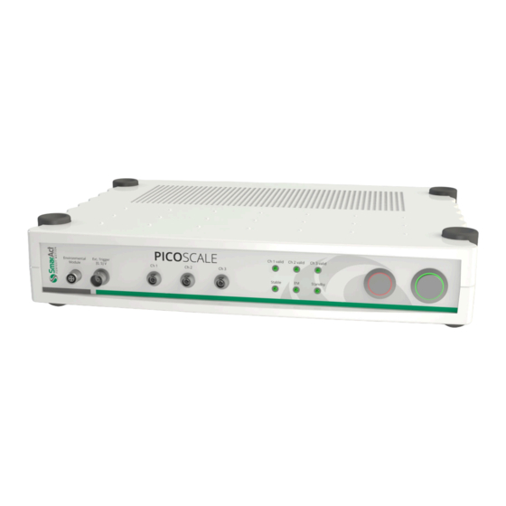
(3) can be connected to the controller. Typically each PICOSCALE system is shipped with some additional accessory (4) like a One-Click cleaner pen, head adapters, mirror mounts, etc. Finally, a PC (5) is required. It is not part of the PICOSCALE system and must be provided by the user. - Page 30 5 PICOSCALE HARDWARE Figure 5.2: (top) Front side of the PICOSCALE Controller with different connectors for the (A) envi- ronmental module, (B) external trigger connector, (C) sensor heads, (D) status LEDs, (E) pilot laser and (F) power button. (bottom) Back side of the PICOSCALE Controller with...
-
Page 31: Interfaces
PC. Via these interfaces a software update can be installed, for example. Besides the main, high-level interfaces, the PICOSCALE offers two low-level interfaces. The Smar- Act SI (5) and SmarAct HSI (7) allow direct access of other SmarAct products to the PICOSCALE data sources. -
Page 32: Optical Outputs
Finally press the power button on the front panel to start the system. Change the main fuse The PICOSCALE Controller is protected with a 2.5 A glass tube fuse with a slow blow timing be- haviour. To prevent permanent damage or fire, the fuse must only be replaced with an equivalent fuse if required (e.g. -
Page 33: Usb Slave Interface
The Ethernet interface is the second main bidirectional communication interface of the PICO- SCALE Controller. The interface is configured via the embedded PC and is able to provide GBit Ethernet. To use the full performance of the PICOSCALE Controller, a GBit Ethernet connection is required. - Page 34 For easy access to the signals we recommend to use the PICOSCALE Breakout-Box which is de- scribed in chapter 5.3. It includes additional buffering of analog and digital IOs and splits the D-Sub 44HD connector to BNC connectors.
-
Page 35: Breakout-Box
PICOSCALE Controller and BOB can be stacked on top of a PICOSCALE Controller. Ventilation holes of the PICOSCALE Controller are passed on to the Breakout-Box, so that heated air can disappear freely. Do not cover the holes to prevent overheating of the PICOSCALE Controller! The connectors on the top of the Breakout-Box are placed in three groups. -
Page 36: Differential Digital Interface Ddi
5 PICOSCALE HARDWARE 5.3.1 Differential Digital Interface DDI The Differential Digital Interface (DDI) provides two differential digital signals, which can be used for different digital protocols, e.g. AquadB and Serial Data. With the Breakout-Box the signals are distributed to three DSub 15 connectors, one per channel. The pin assignment is shown in figure 5.4 and specified in table 5.1. - Page 37 Industry standard AquadB receivers are often able to receive differential quadrature signals as provided by the PICOSCALE Controller. In figure 5.6 the AquadB signals are shown schematically. With the signals A and B four states can be encoded, each state indicates a position increment. So the maximal increment frequency is 4 times the maximum differential pair frequency, in this case...
-
Page 38: Bob Digital Gpios
The direction of the buffers is automatically set with the Ω direction of the digital GPIOs within the PICOSCALE Controller. Main performance parameters are listed in table 5.3 (for the Digital 1-4 signals) and table 5.4 (for the Digital 5-9 signals). -
Page 39: Bob Analog Gpios
/s Resolution Bandwidth 35-45 The Breakout-Box converts the differential DAC1 signal from the PICOSCALE Controller to a single ended 10 V output signal. The output can drive currents up to 35 mA and a capacitive load up to ±... -
Page 40: Sensor Heads
Figure 5.8: Selection of PICOSCALE sensor heads: (A) PS-SH-C01, (B) PS-SH-F01, (C) PS-SH-C03, (D) PS-SH-C02. The PICOSCALE interferometer sensor heads are based on an optical fiber, a fiber ferrule, a colli- mator and a beam splitter cube. The optical fiber (single mode, minimum bending radius 10 mm) is terminated with a 8 ◦... -
Page 41: Environmental Module
Figure 5.10: Environmental Module To measure the environmental parameters (temperature, pressure, humidity), an environmental module can be connected to the PICOSCALE Controller. Since the measurement of the environ- mental conditions is most meaningful close to the sensor head, the environmental module has a small chassis to make it possible to place it in close vicinity of the heads. -
Page 42: Setup And Installation
SCALE components are fragile, please read and follow the information in this chapter carefully! 6.1 System checklist If any cartons have been damaged, contact the shipper or SmarAct sales team at once. The ship- ping boxes for a standard PICOSCALE interferometer should contain the following equipment and documentation: Table 6.1 –... -
Page 43: Unpack The System
SmarAct web page. 6.2 Unpack the system 1. Unpack the PICOSCALE system in an area that is clean and dry. Be very careful, especially with fragile optical and vacuum components. 2. Check each shipping container to be sure you have removed all transport cases and addi- tional items. - Page 44 figure 6.1. Open the plastic cap and push the plastic tube onto the glass fiber end piece until you hear a click. To clean the connectors on the PICOSCALE Controller or vacuum feedthroughs, remove the plastic tube on top of the fiber optic cleaner and then repeat the same process.
-
Page 45: System Power Up
Figure 6.2: Connection of sensor head. NOTICE The PICOSCALE fiber network consists of FC/APC connectors. Do not plug any other optical connector types to the system or its subcomponents. This may cause significant damage to the optical system and dramatically drops the sys- tem performance. -
Page 46: Picoscale Software And Api Installation
6.5 PICOSCALE software and API installation The PICOSCALE Software provides you with a graphical user interface (GUI) as well as an applica- tion programming interface (API). For proper operation of the software Windows 7 or later should be used. -
Page 47: Performing A Picoscale Firmware Update
". The file picoscale-1.0.1__2015-12-01_160436.fw must be copied to a USB memory stick, which has to be plugged into one of the PICOSCALE USB ports. For reducing problems, the stick should be empty (possibly freshly formatted) before copying the new firmware to it. - Page 48 firmware updates. It may also include information about the reason why a system operation like a firmware installation has failed. The " " can additionally be downloaded from the system.log device using the PICOSCALE Control GUI, see chapter 7. The " " file contains status data in a binary format that can sysdiag_<uptime>_<bootcount>.dump be sent to SmarAct for a detailed problem analysis.
-
Page 49: Picoscale Control Gui
The PICOSCALE can be controlled with the LabVIEW based graphical user interface (GUI). It con- tains all main functions to connect to a PICOSCALE system, to adjust it, read the device’s status, configure all installed modules and, of course, read and process the data source values generated by the device. -
Page 50: Configuration Of The Picoscale
7.1.1 Connecting to the controller The PICOSCALE is a multi-user system and up to two users can be connected to the same instru- ment. Therefore, the device offers two interfaces, USB and Ethernet. When more than one user is connected to the instrument, the PICOSCALE requires one main user (full-access connection) who can control the system and change properties, for example. -
Page 51: Status
firmware upgrade and the feature time is set to infinity automatically. 7.1.3 Status The PicoScale status is located in the lower left part of the GUI and displays the current status of the system. The red box (4) in figure 7.1 illustrates the location. The active channels are marked with a green rectangle. - Page 52 Show Log button has red borders. The Clear button deletes all log entries of the GUI. All fields in the PicoScale status are updated auto- matically after connecting to a PICOSCALE sys- tem.
-
Page 53: Adjustment
7.2 Adjustment Figure 7.5: PICOSCALE Adjustment Panel. The three input channels of the PICOSCALE can be configured in the Adjustment Monitor. The goal of the adjustment is to align the interferometer heads in front of the target mirrors and optimize the signal quality. - Page 54 7 PICOSCALE CONTROL GUI Then you have to align sensor head and target mirror with respect to each other. To rate and optimize the alignment, use the Lissajous graph and the signal quality bar. NOTICE The absolute number of the signal quality has no meaning. It is just a temporary indicator which helps you to optimize the current alignment.
-
Page 55: Advanced Trigger
7.3 Advanced Trigger Figure 7.7: Block Diagram of the PICOSCALE Trigger System. The Advanced Trigger System can be purchased as an additional feature for the PICOSCALE system which allows to synchronize internal and external processes. Figure 7.7 shows the block diagram of the Advanced Trigger System. -
Page 56: Trigger Source Configuration
7 PICOSCALE CONTROL GUI 7.3.1 Trigger Source configuration Figure 7.8: Trigger Source Configuration; highlighted by green boxes A trigger source is a basic component in the FPGA, which may be configured to listen to specific events and react in a specific way. The configuration of a trigger source can be controlled within the Advanced Trigger System panel. - Page 57 7 PICOSCALE CONTROL GUI Trigger Event Data Source Value The Data Source Value event performs a state change of the trigger source output when a data source value passes a certain threshold or enters a certain range. Please note that not all data sources are available.
- Page 58 7 PICOSCALE CONTROL GUI Figure 7.10: Summary of trigger conditions. The trigger conditions positive range and negative range are illustrated, which both require an upper and lower threshold to define the appro- priate range. The next field Data Source allows for selecting the desired data source. With the last two fields the Thresholds for the selected condition can be defined.
- Page 59 The next field Channel allows for selecting the desired input pin. The pin labels are in accordance with the pin labels of the PICOSCALE Breakout-Box (BOB). Trigger Event External Trigger The Event External Trigger listens to the external trigger pin that is on the front panel of the PICO- SCALE Controller housing.
-
Page 60: Trigger Configuration
Each trigger has a set of registers, like AND Mask, OR Mask, Logic Operation, as well as Output Mode and Output Delay. The PICOSCALE GUI allows to configure these registers. The Trigger Index drop-down menu in the lower right corner of figure 7.11 allows to select a trigger. - Page 61 In order to debounce or widen the pulses you can select an appropriate Output Mode as well as an Output Delay. The PICOSCALE offers four different Output Modes, which are also illustrated in figure 7.12: •...
- Page 62 7 PICOSCALE CONTROL GUI Input Immediate No Reset Immediate Reset Delayed No Reset Delayed Reset Figure 7.12: Trigger Output Control Behavior (output delay = 10). The input traces are the result of the configured logic operation of the trigger and the eight traces below show the resulting trigger signal for the four output modes.
-
Page 63: Interfaces
7 PICOSCALE CONTROL GUI 7.4 Interfaces The Interfaces panel allows to configure the GPIO interface of the PICOSCALE system. It groups the Digital IO, AquadB and the Digital-to-Analog (DAC) sub-panels. 7.4.1 Digital IO interface configuration Figure 7.13: Configuration Menu of the Digital IO Interface. -
Page 64: Digital Differential Interface (Ddi) Configuration
7.4.2 Digital Differential Interface (DDI) configuration Figure 7.14: Configuration Menu of the Quadrature Interface. The PICOSCALE offers three DDI outputs, which are accessible via the D-Sub 44HD connector at the system’s back plane or more conveniently via the Breakout-Box (BOB). Each of these outputs can be configured as a Quadrature (AquadB) or a Serial Data interface. - Page 65 • Step Frequency. The drop-down menu allows to change the step frequency of the quadra- ture interface with preset values ranging from 100kHz up to 20MHz. The maximum target velocity is calculated by the PICOSCALE according to the configuration of the AquadB channel and displayed underneath the Step Frequency field.
-
Page 66: Dac Interface Configuration
Figure 7.15: Configuration Menu of the DAC Interface. The PICOSCALE offers five DAC outputs that can be configured in the DAC Interface panel. DAC 1 is a fast 10 MHz output channel with 12 bit resolution, DAC 2–5 have 16 bit resolution but their sample rate is limited to 200 kHz. -
Page 67: Modules
Continuous output of a configured clock is realized in the Direct mode of the clock generator. However, when you want to control external devices by the PICOSCALE or vice versa, it is helpful to start and/or stop the clock generators once appropriate trigger conditions are given. For this, the Mode of the clock generator must be set to Triggered and the the corresponding start and stop trigger indices defined (cf. -
Page 68: Arbitrary Signal Generator
Figure 7.17: Configuration Menu of the Arbitrary Signal Generators. In this example a frequency modulation was uploaded as customized signal shape. The PICOSCALE offers basic signal generator functionality with sine, square and sawtooth shapes. Additionally, custom shapes can be uploaded as CSV files. In the configuration panel, see fig. -
Page 69: Calculation System
First, you can define up to four operands (1.1–1.4). Each operand can be a constant, a position/velocity/acceleration value from one of the three PICOSCALE channels, an ADC value, a data source value from the environmental module (temperature, pressure or humidity), signal generator outputs or a counter value. -
Page 70: Counter
Figure 7.19: Configuration Menu of the Counters. The PICOSCALE offers two Counters that may be used as a timer (counting FPGA clock cycles) or as an event counter of trigger events, see fig. 7.19. The counter trigger index can be set to one of the eight trigger indices that can be configured within the Advanced Trigger module. -
Page 71: Streaming Monitor
For continuous data extraction from the PICOSCALE system, data frames can be configured and afterwards streamed to the user PC. In the PICOSCALE GUI the streaming interface can be con- trolled and used within the Stream Monitor panel. Each panel can be undocked using the small symbol next to the "STREAMMONITOR"... -
Page 72: Setting Up A Data Receiver
7 PICOSCALE CONTROL GUI new panel. The more tiles you select, the smaller the individual plots will be as the pattern will be scaled to the window. You may also want to name the new panel appropriately. 7.6.2 Setting up a data receiver Each empty plot panel contains a Configure button that opens a Receiver Settings window shown in... -
Page 73: Manipulate The Data
7 PICOSCALE CONTROL GUI • File The data stream is directed to a file. The data are stored in binary format but using the included Data Reader you can convert them to *.csv files, see section 7.6.5. A header file is stored as well containing information on frame rate and a time stamp. -
Page 74: Picoscale Data Reader
Rate is automatically adjusted to meet the Filter Rate. 7.6.5 PicoScale Data Reader Figure 7.23: PICOSCALE Data Reader. A data file has been loaded and the data are shown. Im- portant information on frame rate and a time stamp are also given. - Page 75 7 PICOSCALE CONTROL GUI The data reader can process the files you have streamed to your hard disk. As the data are stored in binary format you may want to convert them to human-readable CSV files. Therefore, navigate to the Data Reader via File Read Stream Data File.
-
Page 76: Environmental Monitor
Figure 7.24: Environmental Monitor. The Environmental Monitor displays the temperature, humidity and pressure. When an environ- mental module is connected to the PICOSCALE and the GUI subscribes to the corresponding event, temperature, humidity and pressure are recorded automatically. The influence on the mea- surement can be corrected using the Deadpath Correction for the individual channels. -
Page 77: Configuration Manager
Each configuration slot can also be down- and uploaded to *.XML files. The PICOSCALE allows to store specific configuration settings to provide an easy and efficient way to proceed your measurements after a restart of the system. Therefore, there are eight configura- tion slots available, that can be named freely. -
Page 78: Property Dialog
Within the Property Dialog, you can read or write these properties. For a detailed description of the properties, please refer to the PICOSCALE Programmer’s Guide. Please note that changing properties without due consideration may have significant consequences in the performance of the PICOSCALE. -
Page 79: Concluding Remarks
We will be very happy to help and try to find a solution for your precise measurement or implementation issue as quickly as possible. We are convinced that the great versatility of the PICOSCALE offers great potential for many high precision metrology environments. Enjoy your PICOSCALE! - Page 80 United States of America 272-0023 Chiba Korea Japan T/F: +81 47 – 370 86 00 T: +82 2 868 – 10 02 T: +1 415 – 766 9006 Email: info-jp@smaract.com Email: info-kr@smaract.com Email: info-us@smaract.com www.physix-tech.com www.seumtronics.com www.smaract.com PicoScale User Manual...
Need help?
Do you have a question about the PICOSCALE and is the answer not in the manual?
Questions and answers