
Subscribe to Our Youtube Channel
Related Manuals for Alpha Technologies CXPS 24-48-i


Summary of Contents for Alpha Technologies CXPS 24-48-i
- Page 1 CXPS 24-48-i, 8kW DC-DC Converter System Installation & Operation Manual Part # 053-996-B0 Effective: 11/2013 Your Power Solutions Partner member of The Group ™...
- Page 3 Keep it in a safe place. Review the drawings and illustrations contained in this manual before proceeding. If there are any questions regarding the safe installation or operation of this product, contact Alpha Technologies or the nearest Alpha representative. Save this document for future reference.
- Page 4 Electrical Safety WARNING! Hazardous voltages are present at the input of power systems. The DC output from rectifiers and batteries, though not dangerous in voltage, has a high short-circuit current capacity that may cause severe burns and electrical arcing. Before working with any live battery or power system, follow these precautions: Remove all metallic jewelry, such as watches, rings, metal rimmed glasses, or necklaces •...
- Page 5 En cas de questions sur l'installation ou le fonctionnement en toute sécurité de ce produit, contactez Alpha Technologies ou le représentant d'Alpha le plus près. Conservez ce document pour référence future. Symboles de Sécurité...
- Page 6 Sécurité Electrique AVERTISSEMENT ! Des tensions dangereuses sont présentes à l’entrée des systèmes électriques. La sortie CC des redresseurs et des batteries, bien que non dangereuse en termes de tension, a une capacité de courant de court-circuit élevée qui peut causer de graves brûlures et des arcs électriques.
- Page 7 Inspeccione los dibujos y las ilustraciones contenidas en este manual antes de continuar. Si existe cualquier pregunta relacionada con la instalación u operación segura de este producto, póngase en contacto con Alpha Technologies o con su representante de Alpha más cercano. Guarde este documento para referencia futura.
- Page 8 Seguridad Eléctrica ¡ADVERTENCIA ! Hay voltajes peligrosos en la entrada de los sistemas de alimentación. La salida de CC de rectificadores y baterías, si bien no es peligrosa en cuanto al voltaje, cuenta con una alta capacidad de conducción de cortocircuito que puede causar quemaduras graves y arcos eléctricos.
- Page 9 Bewahren Sie es an einem sicheren Ort auf. Sehen Sie sich die Zeichnungen und Illustrationen in diesem Handbuch genau an, bevor Sie fortfahren. Sollten Sie Fragen zur sicheren Installation oder zum Betrieb dieses Produkts haben, wenden Sie sich bitte an Alpha Technologies oder den nächstgelegenen Alpha-Vertreter. Bewahren Sie dieses Dokument für den zukünftigen Gebrauch auf.
- Page 10 Elektrische Sicherheit WARNUNG! Am Punkt der Stromeinspeisung liegen gefährliche Spannungen vor. Der Gleichstromausgang von Gleichrichtern und Batterien weist zwar keine gefährliche Spannung auf, die Kurzschlussstrom-Kapazität ist jedoch sehr hoch, was zu ernsthaften Verbrennungen und Lichtbögen führen kann. Befolgen Sie die folgenden Vorsichtsmaßnahmen, bevor Sie mit einer spannungsführenden Batterie oder einem Stromversorgungssystem arbeiten: Legen Sie sämtlichen Schmuck aus Metall wie z.B.
-
Page 11: Table Of Contents
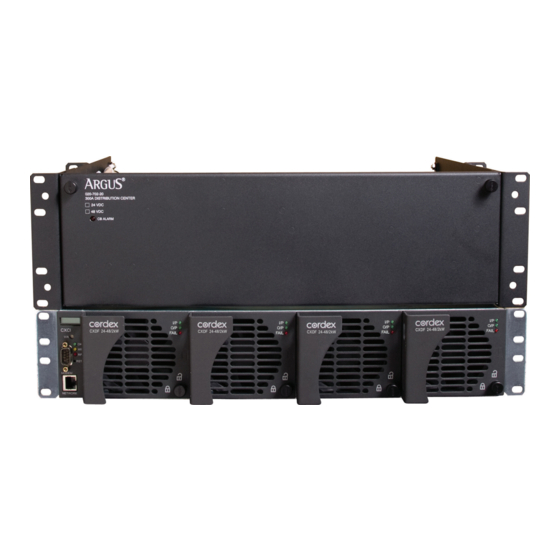
ABLE OF ONTENTS ................................1 NTRODUCTION Scope of the Manual ............................1 Product Overview ............................1 System Configurations ............................ 2 Accessories ..............................2 .................................. 3 EATURES System Overview ............................. - Page 12 IGURES Figure 1–Front view of the 053-996-20-000 rail mount CXPS 24-48-i 8kW DC-DC Converter System ......1 Figure 2–DCP03 configured for 18 load breakers ......................3 Figure 3–Internal alarm card ............................3 Figure 4–Internal alarm card and CXCI/CXCI+ I/O terminal block .................. 4 ...
-
Page 13: Introduction
• Product Overview The CXPS 24-48-i is a complete integrated 24Vdc to 48Vdc converter system utilizing the advanced Cordex CXCI/CXCI+ controller and 24-48V 2kW converter modules. The DCP03 300A distribution center provides front access for DC distribution and site controller connections. The system provides a maximum capacity of 8kW (148A @ 54Vdc). -
Page 14: System Configurations
System Configurations The system is available to order in the following configurations: Description Part Number CXPS 24-48-i, Cordex base 24V-48V 8kW converter system, 19/23” rail mount ......053-996-20-000 Accessories This product is available to order with the following accessories: Description Part Number Cordex DC/DC 2kW converter, 24V In –... -
Page 15: Features
Distribution Configurations The DCP03 contains 18 total AM-type plug-in breaker positions with two-hole connection points for both load (hot) output and the ground return bus. The breaker distribution, for the CXPS 24-48-i, is configured for 18 load breaker positions. Figure 2–DCP03 configured for 18 load breakers 2.2.2... -
Page 16: Figure 4-Internal Alarm Card And Cxci/Cxci+ I/O Terminal Block
All I/O connections are made via screw terminal blocks. Refer to the customer connections (“–08”) drawing at the rear of this manual for details on terminal block assignments. NOTE: The 4R/8D ADIO board does not come with the CXPS 24-48-i system and is purchased separately. Consult factory for options. -
Page 17: Cordex Integrated System Controller (Cxci/Cxci+)
Cordex Integrated System Controller (CXCI/CXCI+) The controller is mounted in the converter system shelf and brings advanced monitoring technology to the Cordex series of converters. This compact system controller is designed for seamless operation and set up of Alpha power systems and is equipped with the complete range of Cordex software features, including the following: Designed to communicate directly with Cordex converters •... -
Page 18: Figure 7-Cordex Cxci+ Model System Controller Front Panel
2.3.4 Modem Port (not available on the CXCI+) The Modem port (front panel DB-9 connector, Figure 6) is designed for CXCI connection to Alpha Technologies’ Cordex DC Modem #018-585-20 (complete with Alpha cable). CAUTION: Connect only Alpha-supplied modem and cable; otherwise, equipment damage can result. -
Page 19: Cordex 24-48/2Kw Converter
2.3.6 Analog Input Channels The CXCI/CXCI+ has analog input channels for voltage, current, and temperature. 2.3.6.1 Voltage Inputs Two voltage input channels, V1 and V2, provide monitoring of discharge and charge voltage. The CXCI/CXCI+ software is pre-configured to monitor V2 for load and for battery voltage. V2 is used as the system reference for converter float voltage, low voltage disconnect (LVD), system high voltage alarm, and system low voltage alarm. - Page 20 2.4.1 Alarms Converter Module Fail alarms consist of a group of (major) alarm conditions that are considered “serious” or an immediate threat to service: Converter failure • Output fuse failure • Converter off • Thermal shutdown • Input Voltage is out of range •...
-
Page 21: Inspection
If the original container is unavailable, make sure the product is packed with at least three inches of shock-absorbing material to prevent shipping damage. NOTE: Alpha Technologies is not responsible for damage caused by the improper packaging of returned products. Check for Damage Prior to unpacking the product, note any damage to the shipping container. -
Page 22: Installation
Installation This chapter is provided for qualified personnel to install and interconnect the power components within the Alpha power system. Regarding battery installation, refer primarily to the manufacturer’s guidelines for more specific information. NOTE: To aid the user with installation, frequent reference is made to drawings located at the rear of this manual. Safety Precautions Refer to the Important Safety Instructions near the front of this manual. -
Page 23: Power System Assembly And Mounting
Power System Assembly and Mounting WARNING! This system is designed to be installed in a restricted access location that is inaccessible to the general public. The power system must be mounted in a clean and dry environment. Sufficient free space must be provided at the front and rear of the power system. -
Page 24: Wiring
Wiring This chapter provides cabling details and notes on cable sizing for DC applications with respect to the product. WARNING Ensure that power is removed by turning off converters and removing battery line fuse (if applicable) or connection before attempting work on the wiring connections. Use a voltmeter to verify the absence of voltage. -
Page 25: Input/Output Connections
24Vdc Input to System The system contains bus (bar) input for hot and return connections. The CXPS 24-48-i system is configured for wiring with respect to converter shelf output integration to the distribution panel. Refer to Figure 10 below. +24Vdc input is connected to the converter shelf. -
Page 26: Alarm Connections
5.3.4 Breaker Return (Ground) Connections Connect breaker (ground) output connections to the DCP03 ground bar. Secure two hole lugs to the 1/4” holes (on 5/8” centers) using the supplied hardware with the DCP03. Cables should run directly out the rear of the distribution center above the breaker (hot) output cables. -
Page 27: Can Serial Ports
4R/8D ADIO wire routing optional Cable clamp System internal and 4R/8D ADIO CAN ports CXCI/CXCI+ wire routing optional example Figure 12–DCP03 wire routing example (Photo is for reference only – subject to installation requirements) CAN Serial Ports Two CAN Serial ports (modular jacks with offset latches), for communications with Alpha’s Cordex converters and other CAN-enabled equipment (nodes) on the same system, are located on the side of the converter shelf. -
Page 28: Signal Wiring Connections For Cxci/Cxci
Connect using a standard network crossover cable. 5.6.3 CXCI Modem Port (Alpha Cable) The Modem port (front panel DB-9 connector, Figure 6) is designed for CXCI connection to Alpha Technologies’ Cordex DC Modem #018-585-20. Connect using the Alpha-supplied cable. CAUTION Connect only Alpha-supplied modem and cable;... -
Page 29: Figure 14-Showing Digital Input Connection Method
5.7.2.1 Connection Method Typical Alpha systems use the “reset with Hot and trigger with Ground” connection. The digital input is wired in such a way that the Hot is wired directly into one of the input terminals; e.g., negative input for -48V systems. The other input terminal is wired to the Ground (common) of the system through a relay (dry contact –... -
Page 30: System Startup
System Startup Visually inspect the installation thoroughly. After completing the system installation and power system wiring, perform the following startup and test procedure to ensure proper operation: Check System Connections Ensure power is off, battery breaker is off (if applicable), and all modules are removed from the shelf. •... -
Page 31: Cxci/Cxci+ Reset
CXCI/CXCI+ Reset CAUTION: Before removing a CXCI/CXCI+ from a live system, or performing controller maintenance, an external LVD inhibit (or override) is required to avoid a disruption of service. 6.4.1 Soft Reset The reset button, located on the front panel of the optional CXCI/CXCI+, is for restarting the microprocessor. When pressed momentarily, the unit beeps twice then resets. -
Page 32: Maintenance
Maintenance Although very little maintenance is required with Alpha systems, routine checks and adjustments are recommended to ensure optimum system performance. Qualified service personnel should do repairs. The following table lists a few maintenance procedures for this system. These procedures should be performed at least once a year. -
Page 33: Cxci/Cxci+ Replacement Procedure
CXCI/CXCI+ Replacement Procedure 7.2.1 Replacing a CXCI Controller 1. Write down the CXC communication information: dynamic or static IP, IP address, and gateway. 2. Connect a laptop to CXC per software manual; standard network crossover cable to Ethernet port. 3. Save the CXC configuration file (see software manual Logs and Files > Manage Configuration File > Save Full Site Configuration). -
Page 34: Figure 16-Showing Cxci Module Removal (Replacement)
Remove front Remove the CXCI mounting screw to by disengaging the release the CXCI module from the assembly rear connector (inside the shelf) Use the baffle to grip the assembly and slide along the shelf bottom Figure 16–Showing CXCI module removal (replacement) 9. -
Page 35: Figure 17-Showing Cxci+ Controller Module Replacement
7. Place the new CXCI+ controller module on the shelf bottom and slide into the rear connector at the back of the slot. Figure 17–Showing CXCI+ controller module replacement 8. Replace the DB connector on the back of the CXCI+ at the rear of the shelf 9. - Page 36 10. Log on to the CXC and go to Logs and Files > Manage Configuration File > Upload Site Configuration and select the saved *.cfg file. After the upload do a Submit Changes. Make sure the site information is checked to save it, and click Accept. 11.
-
Page 37: Warranty
8.1 Warranty Alpha Technologies Ltd. warrants all equipment manufactured by it to be free from defects in parts and labor, for a period of two years from the date of shipment from the factory. The warranty provides for repairing, replacing or issuing credit (at Alpha’s discretion) for any equipment manufactured by it and returned by the customer to the... -
Page 38: Acronyms And Definitions
Acronyms and Definitions Alternating current ANSI American National Standards Institute American Wire Gauge British thermal unit Controller area network Canadian Electrical Code Circular mil area Canadian Standards Association Cordex™ series; e.g., CXC for Cordex System Controller Direct current Distribution Center Plug-In DHCP Dynamic Host Configuration Protocol Electromagnetic compatibility Electromagnetic interference... - Page 39 0 to 95% non-condensing Elevation: -500 to +2800 m (-1640 to 9186 ft) Alpha Technologies Ltd. 053-996-B1 Rev B Printed in Canada. © 2012 Alpha Technologies Ltd. ALPHA and CORDEX are trademarks of Alpha Technologies Ltd. All Rights Reserved. Page 1 of 3...
- Page 40 2x 350MCM ≥ 90°C rated @ 60°C Output Wire Size (minimum): 3/0AWG ≥ 90°C rated Alpha Technologies Ltd. 053-996-B1 Rev B Printed in Canada. © 2012 Alpha Technologies Ltd. ALPHA and CORDEX are trademarks of Alpha Technologies Ltd. All Rights Reserved. Page 2 of 3...
- Page 41 The above information is valid at the time of publication. Consult factory for up-to-date ordering information. Specifications are subject to change without notice. Alpha Technologies Ltd. 053-996-B1 Rev B Printed in Canada. © 2012 Alpha Technologies Ltd. ALPHA and CORDEX are trademarks of Alpha Technologies Ltd. All Rights Reserved. Page 3 of 3...
- Page 42 Consult the dealer or an experienced radio/TV technician for help. • Alpha Technologies Ltd. 7400233-S0 Rev C Printed in Canada. © 2013 Alpha Technologies Ltd. ALPHA and CORDEX are trademarks of Alpha Technologies Ltd. All Rights Reserved. Page 1 of 3...
- Page 43 Ethernet RJ-45, Alpha Modem DB-9, CAN [see shelf specifications] CXCI+ Communication Ports: Ethernet RJ-45, CAN [see shelf specifications] Alpha Technologies Ltd. 7400233-S0 Rev C Printed in Canada. © 2013 Alpha Technologies Ltd. ALPHA and CORDEX are trademarks of Alpha Technologies Ltd. All Rights Reserved. Page 2 of 3...
- Page 44 The above information is valid at the time of publication. Consult factory for up-to-date ordering information. Specifications are subject to change without notice. Alpha Technologies Ltd. 7400233-S0 Rev C Printed in Canada. © 2013 Alpha Technologies Ltd. ALPHA and CORDEX are trademarks of Alpha Technologies Ltd. All Rights Reserved. Page 3 of 3...
- Page 47 567-809-19 18.94 UNLESS OTHERWISE SPECIFIED THESE DESIGNS AND SPECIFICATIONS ARE DIM ARE IN INCHES CONFIDENTIAL, REMAIN THE PROPERTY OF 0.040 ALPHA TECHNOLOGIES LTD., AND SHALL NOT BE X.XX 0.020 COPIED OR USED WITHOUT ITS WRITTEN CONSENT X.XXX 0.010 APPROVALS DATE...
- Page 48 THESE DESIGNS AND SPECIFICATIONS ARE DIM ARE IN MM CXCI/CXCI+ SYSTEM CONTROLLER CXDF 24-48/2kW CONVERTER CONFIDENTIAL, REMAIN THE PROPERTY OF CXCI #747-502-20 012-526-20 ALPHA TECHNOLOGIES LTD., AND SHALL NOT BE COPIED OR USED WITHOUT ITS WRITTEN CONSENT CXCI+ #7400232-001 X.XX 0.25 APPROVALS DATE...
- Page 49 NOTE: REFER TO 053-996-05 WIRING SCHEMATIC FOR MORE INFORMATION SYSTEM RETURN (COMMON) CXCI/CXCI+ SYSTEM I/O DB-25 CONNECTOR +24V INPUT (HOT) BUSBAR DISTRIBUTION -48V (HOT) OUTPUT BUSBAR BUSBAR (+48/-24V) TERMINATION (FACTORY CONNECTION) 3/8" HOLES ON 1" CENTERS (FACTORY CONNECTION) 3/8" HOLES ON 1" CENTERS 3/8"-16 HARDWARE CHASSIS GROUND CONNECTIONS (SUPPLIED)
- Page 50 CHASSIS GROUND CHASSIS GROUND #10-32 STUD #10-32 STUD 18X BREAKER OUTPUT (-48V) TERMINATIONS 1/4-20 STUDS ON 5/8" CENTERS 18X BREAKER RETURN (COM) TERMINATIONS 1/4-20 TAPPED HOLES ON 5/8" CENTERS TOP VIEW (DOOR OPEN) TITLE: CONNECTION,CXPS 24 48-i CONVERTER SYSTEM SIZE DWG NO.
- Page 51 020-702-20 CONNECTION DETAILS SYSTEM ASSIGNED (RESERVED) FORM "C" RELAY ALARM OUTPUT CONNECTIONS K2 = SYSTEM MINOR ALARM 2X TEMPERATURE SENSOR K3 = SYSTEM MAJOR ALARM INPUT CONNECTIONS T1 & T2 AVAILABLE (OPTIONAL) 2X FORM "C" RELAY ALARM OUTPUT CONNECTIONS K1 AND K4 AVAILABLE (OPTIONAL) RESERVED FOR INTERNAL SYSTEM WIRING...
- Page 56 Canada and USA: 1-888-462-7487 International: +1-604-436-5547 Visit us at www.alpha.ca Due to continuing product development, Alpha Technologies reserves the right to change specifications without notice. Copyright © 2013 Alpha Technologies. All Rights Reserved. Alpha® is a registered trademark of Alpha Technologies.
Need help?
Do you have a question about the CXPS 24-48-i and is the answer not in the manual?
Questions and answers