
Related Manuals for RHINO MOTION CONTROLS RMCS-3002


Summary of Contents for RHINO MOTION CONTROLS RMCS-3002
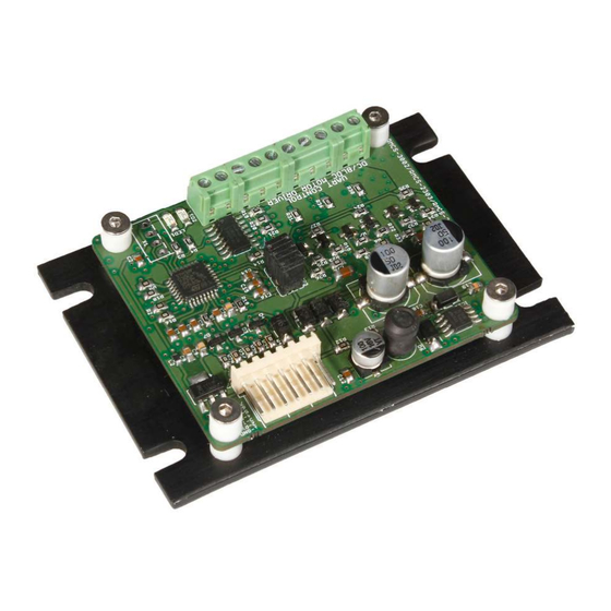
- Page 1 BRUSHLESS DC MOTOR DRIVE ASCII Modbus (Model No: RMCS – 3002) Operating Manual v1.0...
-
Page 2: Table Of Contents
Contents Introduction – Salient Features ..................3 Technical specifications and Pin description ..............4 Slave ID Addressing ...................... 5 Modbus Registers ......................6 Modbus Register Mapping .................... 8 Control Modes ......................10 Hardware Connection of Analog Open and Closed Loop Mode: ......10 Mode 0 Analog Open Loop Mode: ............... -
Page 3: Introduction - Salient Features
Introduction – Salient Features Rhino Motion Controls RMCS-3002 with UART ASCII is a high performance brushless dc drive (10–30 V DC) designed for optimized operation of Rhino brushless DC motors with Hall sensor feedback. This is an amazing cost effective solution to provide closed loop/open loop control for various applications. -
Page 4: Technical Specifications And Pin Description
Technical specifications and Pin description Supply Voltage and Current Ratings: Specification Units Comments Supply Voltage Volts DC Between +Ve and GND Phase Current Amps Peak 3 Amps per phase Pin description of the drive is as per below image: Pin No. Description Pin No. -
Page 5: Slave Id Addressing
Slave ID Addressing: The second unique feature in this drive is that a single controller can be used to control seven drives at the same time using the physical jumpers. Using the Modbus Poll software, the slave ID can be set from 1 to 247. However, in this driver, we can set slave ID from 1 to 7 using physical jumpers also. -
Page 6: Modbus Registers
Modbus Registers Range Data /Command Size Description Address Register Acces Function Specification And Default (Decimal value in HEX (Decimal) To save parameters in Drive (EEPROM) send Hex value Write XXFF to Address 0. FF (255) Parameters Where XX is slave ID ranging to EEPROM from 1 to F7(1- 247) Read /... - Page 7 Mode byte:03 Analog 0301(769) Enable Motor Control byte:01 Closed Loop Mode Mode byte:03 0300(768) Disable Motor (Mode 3) Control byte:00 Mode byte:03 0303(771) Brake Control byte:03 Analog Closed Enable Minimum Speed Control Mode byte:04 Loop Minimum Mode. Set PWM speed in Control byte:01 0401(1025) Speed Control...
-
Page 8: Modbus Register Mapping
Modbus Register Mapping ➢ Device Modbus Address(MOD _ID) Address: 0x00 (40001) Default value: 0x0100 MOD_ID[15:8] SP[7:0] Bits 15:8 MOD_ID[15:8]: Modbus address register bits Default: 0x01 Maximum value: 0xF7 Minimum value: 0x01 Bits 7:0 SP[7:0]: Save parameters Default: 0x00 If slave id is 7 then by writing 0x07FF in this address it will save parameters in eeprom and writing 0x0800 will load default value in drive. - Page 9 ➢ PWM Register(PWM) Address: 0x04 (40005) Default value: 0x0000 PWM[15:0] Bits 15:0 PWM [15:0]: PWM Default: 0x0000 Maximum value: 0x12C0 Minimum value: 0x0000 PWM Signal depends on the application. PWM range of this drive is 0-4800 (decimal) value. In Digital open Loop mode speed can be controlled by PWM.
- Page 10 ➢ Current Feedback Register(CUR) Address:0x0A(40011) Default value: 0x0000 CUR[15:0] Bits 15:0 CUR [15:0]: Curent Feedback Register This register stores current drawn value. Unit is A (Ampere). ➢ Movement Limit(MVL) Address: 0x0C (40013) Default value: 0x7FFF MVL[15:0] Bits 15:0 MVL [15:0]: Movement Limit Register In digital closed loop mode (01) there is option to control the length of motion, once the length of that motion is exceed the motor will automatically enter in brake condition.
-
Page 11: Control Modes
Control Modes: Motor can be run in five different modes: Mode 0: Analog Open Loop Mode Mode 1: Digital Closed Loop Mode Mode 2: Digital Open Loop Mode Mode 3: Analog Closed Loop Mode Mode 4: Analog Closed Loop Minimum Speed Control Mode Hardware Connection of Analog Open and Closed Loop Mode: The potentiometer connections need to be provided only to run motor in Analog Mode only. - Page 12 Motor Pin outs Drive Pin outs Motor Wire Color Pin No. Description Black VCC(5 V DC ) +5VDC Hall W Blue ENC_B/Hall W Hall V Green ENC_A/Hall V Hall U Yellow Thick blue Hall U Motor- / V Thick green Motor- / V Motor+ / U Thick yellow...
-
Page 13: Mode 4: Analog Closed Loop Minimum Speed Control Mode
Mode 0 Analog Open Loop Mode: In this mode the speed of the Rhino BLDC motor can be controlled by an externally connected Potentiometer. User can increase or decrease the speed manually based on requirement using potentiometer. The drive will provide full torque at all speeds within the range. However the potentiometer has to be connected to 3.3 volts so as to not damage the drive. -
Page 14: Hardware Connection Of Digital Open And Closed Loop Mode
Hardware Connection of Digital Open and Closed Loop Mode: In both these mode no need to connect external potentiometer. Mode 1 Digital Closed Loop Mode: In this mode the frequency and direction of the Rhino BLDC motor is settable / controllable via a Computer / Arduino Controller board / any other Modbus ASCII compatible device. -
Page 15: Mode 2 Digital Open Loop Mode
Example of position control mode: • Set the speed frequency in register 6 to say 40 Hz • Set the distance of travel in register 12 to say 100 • Set the mode in 40003 (2) and enable with hex value 0101 (257). •... -
Page 16: Troubleshooting
Troubleshooting If motor is not moving in digital closed loop mode read value in frequency register. If motor is not moving in digital open loop mode read value in PWM register. If motor is not running in analog mode check external potentiometer connections and check enable connection as it must be connected with Gnd. - Page 17 © Rhino Motion Controls, 2020 Neither the whole nor any part of the information contained in, Copyrig or the product described in this manual, may be adapted or reproduced in any material or electronic form without the prior written consent of the copyright holder. This product and its documentation are supplied on an as-is basis and no warranty as to their suitability for any particular purpose is either made or implied.
Need help?
Do you have a question about the RMCS-3002 and is the answer not in the manual?
Questions and answers