Table of Contents
Advertisement
Quick Links
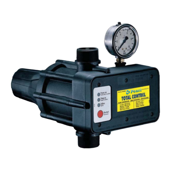
RESIDENTIAL PUMP CONTROLLER - MOD. PCTC16F16S
File No: E191502 Mod. CP
TOTAL CONTROL can be installed on surface and submersible pumps for residential, domestic irrigation
and booster systems.
- Provides for an adjustable downstream pressure.
- Avoids pressure and flow fluctuations.
- Eliminates pump pressure switch.
- Built-in pressure and flow switch.
-
B
i u
- t l
n i
c
h
e
k c
v
a
v l
. e
-
B
u
- t l i
n i
r d
- y
u r
n
p
o r
e t
READ THESE INSTRUCTIONS CAREFULLY BEFORE INSTALLATION
INSTALLER - PLEASE LEAVE THIS MANUAL WITH THE UNIT OR GIVE TO END USER.
OWNER'S MANUAL
115 / 230 VAC
FEATURES & BENEFITS
c
o i t
. n
DUAL VOLTAGE UNIT
- Dual voltage 115 / 230 VAC.
- All inoxidable components.
- Assists in absorbing water hammer.
- Can be used with or without pressure tank.
-
S
m i
p
e l
n i
t s
l l a
t a
-
N
o
m
a
n i
e t
n
a
c n
™
o i
n
s
a
v
e
s
s
p
c a
e
a
n
d
t
m i
e
e r
q
i u
e r
. d
. e
Advertisement
Table of Contents

Subscribe to Our Youtube Channel
Summary of Contents for Total Control PCTC16F16S
- Page 1 DUAL VOLTAGE UNIT File No: E191502 Mod. CP FEATURES & BENEFITS TOTAL CONTROL can be installed on surface and submersible pumps for residential, domestic irrigation and booster systems. - Provides for an adjustable downstream pressure. - Dual voltage 115 / 230 VAC.
-
Page 2: Table Of Contents
Troubleshooting…………………………………………………………………………….………. 3 Maintenance and spare parts……………………………………………………………….…….. 3 Hydraulic connection to the system……………………………………………………….……... 4 Conduit connections………………………………………………………………………….……. 4 Typical TOTAL CONTROL installation on surface and submersible pumps.…………….…. 5 TOTAL CONTROL installation guidelines and warnings.…………………………………..6 When to use pressure tank………………………………….………………………………..…… 6 Calibration.…………………………………………………………………………………….…….. 7 Pressure loss………………………………………………………………………………………... -
Page 3: Precautions And Warnings
Be sure well is equipped with a pressure relief valve. Do not allow pump, TOTAL CONTROL, piping, or any other system component containing water to freeze. Freezing may damage system, leading to injury or flooding. Allowing TOTAL CONTROL or system components to freeze will void warranty. -
Page 4: Technical Specifications
• Displays when power is connected to TOTAL CONTROL unit. Power on • ( green ) In the event of a temporary power outage, TOTAL CONTROL resets automatically when power is restored. • Pump on Displays when pump is running. -
Page 5: Hydraulic Connection To The System
Open the electronic box cover by removing the six screws from the cover. Line voltage and pump wires to the TOTAL CONTROL should be supplied through “liquid- tight” nonmetallic conduit fittings rated “NEMA 12” or “UL type 12” to achieve NEMA Type 12 enclosure rating. -
Page 6: Typical Total Control Installation On Surface And Submersible Pumps
- 5 -... -
Page 7: Total Control Installation Guidelines And Warnings
- 6 -... -
Page 8: Calibration
Max 95 psi Max 174 psi 45 psi TOTAL CONTROL has a built-in pressure reducing valve, allowing for downstream pressure adjustement according to system requirements. System pressure can be adjusted between minimum 45 psi and maximum 95 psi. Open a tap to start up the pump, close the tap and wait for pump to stop, then check the system pressare on the pressure gauge, normally factory calibrated at 45 psi. -
Page 9: Pressure Adjusting Procedure
The system pressure (P2) must be approximately 25 psi lower than the pump pressure (P1), and approximate- ly 15 psi higher than the pressure in the water column feeding the TOTAL CONTROL (P3). If the pressure of the pump (P1) fails to reach the values indicated in the pressure adjustment table, the pump will stop working. -
Page 10: Electrical Connections
Check voltage of pump and supply to determine pump motor FLA and follow applicable TOTAL CONTROL wiring diagram. If pump motor FLA exceeds TOTAL CONTROL rating, use magnetic starter wiring diagram for the applicable voltage ( see pages 12, 13). -
Page 11: Installation Wiring Diagram - 230Vac 2-Wire Pumps Up To 20 Fla
INSTALLATION WIRING DIAGRAM - 230VAC 2-WIRE PUMPS UP TO 20 FLA INSTALLATION WIRING DIAGRAM - 230VAC 3-WIRE PUMPS UP TO 20 FLA - 10 -... -
Page 12: When To Use Contactors
On 230V installations pump motor full load amps exceed 20 FLA. • On all three-phase applications. Remember, match coil voltage on contactor with TOTAL CONTROL voltage. Either 115V or 230V coils may be used. Use of magnetic starter to avoid damage to the device is determined by pump motor. -
Page 13: Installation Wiring Diagram - 208 Vac Or 230 Vac Three Phase 3-Wire Pumps
- 12 -... -
Page 14: Installation Wiring Diagram - 230Vac 3-Wire Pumps Exceeding 20 Fla
INSTALLATION WIRING DIAGRAM - 230VAC 3-WIRE PUMPS EXCEEDING 20 FLA OVERALL DIMENSIONS - 13 -... -
Page 15: Electronic Box Replacement
ELECTRONIC BOX REPLACEMENT Before removing the electronic box ensure that power unit is off and unit is depressurized. 1) Remove the box cover and disconnect the electrical wires. 2) Take off the box by removing the three screws attaching the electronic box to the unit body. - Page 16 TOTAL CONTROL is warranted to be free of defects occurring either in hydraulic or electronic parts for a period of one year from the date of installation w hen installed by a licensed professional in accordance with the product manual and due professional care.

Need help?
Do you have a question about the PCTC16F16S and is the answer not in the manual?
Questions and answers