
Related Manuals for Opvimus NOVA-500


Summary of Contents for Opvimus NOVA-500
- Page 1 SISTEMA NOVA NOVA SYSTEM Manual de instalación y funcionamiento v .0 Installation and operating instructions v .0...
- Page 2 NOVA Sistema de Evacuación por Voz INSTRUCCIONES DE SEGURIDAD: INSTALACIÓN: La instalación de este sistema es muy simple. Recomendamos que se tome su tiempo en leerse este manual a fin de asegurarse de realizar una instalación correcta. Nunca instale este equipo en un ambiente con altas temperaturas, polvo, humedad o vibraciones ya que podría alterar su rendimiento o reducir su vida útil. INSTRUCCIONES DE SEGURIDAD IMPORTANTES 1. Lea las instrucciones. 2. Guarde este manual. 3. Preste atención a todas las advertencias. 4. Siga las instrucciones. 5. No utilice este equipo cerca del agua. 6. Límpielo solamente con un paño seco. 7. No bloquee las aberturas de ventilación. Instálelo de acuerdo con las instrucciones del fabricante. ...
-
Page 3: Table Of Contents
NOVA Sistema de Evacuación por Voz ÍNDICE COMPONENTES DEL SISTEMA .................... 4 1.1. NOVA‐500 ........................ 4 1.2. NOVA‐500S ........................ 4 1.3. NOVA‐12RM........................ 4 NOVA‐500 Y NOVA‐500S ....................... 5 2.1. PANEL FRONTAL ...................... 5 2.2. PANEL POSTERIOR ...................... 7 2.3. - Page 4 NOVA Sistema de Evacuación por Voz SOFTWARE ......................... 17 5.1. INSTALAR Y EJECUTAR EL SOFTWARE ................ 17 5.2. CONNEXIÓN AL SOFTWARE .................. 18 5.3. MENÚ PARAMETER SETTING .................. 18 5.3.1. Menu Equipment ‐ Chime volume .............. 19 5.3.2. Menú Equipment – HOST ................... 19 5.3.3. Menú Equipment ‐ EX‐HOST ................ 20 5.3.4. Menú Equipment – Charger ................ 21 ...
-
Page 5: Componentes Del Sistema
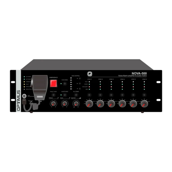
NOVA Sistema de Evacuación por Voz 1. COMPONENTES DEL SISTEMA 1.1. NOVA‐500 Controlador del sistema, unidad principal. Puede controlar hasta 120 zonas. 500 W RMS. 6 zonas con control de volumen individual. Micrófono de bombero en el panel frontal. Función de emergencia con dos mensajes de emergencia, Alerta y Evacuación. Supervisión de micrófono, amplificador, mensajes de emergencia, líneas de altavoces... 6 entradas de audio. 8 entradas de contacto y 8 salidas de contacto. 6 salidas para atenuadores de 24 Vcc. Alimentación AC / DC. Software de configuración y control. Registro de 3000 eventos. Conexión para amplificador de reserva*. Bus de 600 m entre todos los componentes del sistema, con redundancia opcional. 1.2. NOVA‐500S ... -
Page 6: Nova-500 Y Nova-500S
NOVA Sistema de Evacuación por Voz 2. NOVA‐500 Y NOVA‐500S 2.1. PANEL FRONTAL 1. Indicador AC. Verde si la alimentación 110‐250 Vca está disponible, y amarillo cuando funciona a 24 Vcc. 2. Indicador DC. Verde si la alimentación de 24 Vcc está disponible; de lo contrario, apagado. Amarillo cuando falla la alimentación 24 Vcc (si la supervisión 24 Vcc está activada). 3. Indicador COM. Verde si el conector LAN está conectado a Ethernet, apagado si no hay conexión. 4. Indicador FAULT. Amarillo si se detecta algún fallo. Apagado si el sistema está funcionando correctamente o si la supervisión está desactivada. 5. Indicador del micrófono de Emergencia. Verde si el micrófono está activo, amarillo si el micrófono está averiado o desconectado. Apagado si el micrófono funciona correctamente, pero no está activo. ... - Page 7 NOVA Sistema de Evacuación por Voz 9. Botón e indicador de mensaje EVAC. Púlselo, en modo de Emergencia, para activar el mensaje de evacuación. Verde si se está transmitiendo el mensaje. Amarillo ante un fallo en el mensaje. Apagado en estado normal. 10. Botón e indicador de mensaje ALERT. Púlselo, en modo de Emergencia, para activar el mensaje de ALERTA. Verde si se está transmitiendo el mensaje. Amarillo ante un fallo en el mensaje. Apagado en estado normal. ...
-
Page 8: Panel Posterior
NOVA Sistema de Evacuación por Voz 2.2. PANEL POSTERIOR 1. Entrada alimentación 24 Vcc. Entrada de 24 Vcc para batería sellada de plomo‐ácido, SAI o producto equivalente. 2. 6 salidas de líneas de altavoces AB. Salidas de altavoces de 100 V. 3. 6 salidas de atenuador a 24 Vcc. Las 6 se activan a la vez durante avisos de emergencia o generales. Máximo 0,2 A por contacto. Potencia máxima total 28 W. 4. 8 contactos de salida. Contactos de salida de relé multifuncionales programados por software. 5. 8 contactos de entrada. Contactos de entrada multifuncionales programados por software. NOVA Versión 1.0 Page 7 of 34... -
Page 9: Nova-500 Operación
NOVA Sistema de Evacuación por Voz 6. Entrada LAN. (Solo NOVA‐500). Conexión Ethernet, se utiliza para conectar el software del PC y configurar el sistema. 7. Conectores de expansión de Bus. Conectores de entada y salida de bus, utilizados para conectar el bus entre equipos. 8. Tarjeta de memoria del sistema (Solo NOVA‐500). Tarjeta SD donde se almacenan todos los ajustes, mensajes y configuraciones del sistema. 9. Toma a tierra. 10. Conectores de interfaz para amplificador de reserva. Salida de audio de 0 dB y entrada de audio de 100 V, se utiliza para conectar un amplificador de potencia de reserva. 11. Contacto de salida FAULT. Contacto de salida activado cuando se detecta cualquier fallo. 12. Contacto de salida EVAC STATE OUTPUT. Contacto de salida activado en modo Emergencia. 13. Contacto de entrada EMERGENCY RESET. Cierre este contacto para restablecer el modo de Emergencia. 14. Entrada de audio XLR. Entrada de audio a nivel de línea, 0 dB. 15. Entrada de audio XLR . Entrada de audio a nivel de línea, 0 dB. 16. Controles de volumen para entradas INPUT 1‐6. 17. Entradas de audio RCA. Entrada de audio a nivel línea, 0 dB. ... -
Page 10: Envío De Mensajes De Emergencia Desde Contactos
NOVA Sistema de Evacuación por Voz 2.3.2. Envío de mensajes de Emergencia desde contactos Los mensajes de Emergencia se activan cerrando contactos de entrada en la trasera de la unidad. Las entradas de contacto se pueden asignar a mensajes de ALERT o EVAC según configuración. Es posible también configurar su modo de activación como Nivel o Pulso. Una vez activado el modo Emergencia por contactos, el botón de EMERGENCY se ilumina en rojo y se activa el zumbador. Puede detener el zumbador presionando el botón ACK. ... -
Page 11: Nova-12Rm
NOVA Sistema de Evacuación por Voz 3. NOVA‐12RM 3.1. DESCRIPCIÓN El pupitre NOVA‐12RM se utiliza para el control remoto del sistema. Incluye 12 teclas programables con las siguientes funciones: Selección de zona/grupo para avisos. Activación de mensajes internos, individuales o lista como BGM. Asignación de una entrada de audio a zonas de salida como BGM. Audio balanceado y alimentación Phantom de 24 V, no se requiere fuente de alimentación. Se conecta al sistema con un cable CAT5 (mínimo UTP, recomendado FTP). Se pueden instalar hasta 32 unidades y a una distancia máxima del cable de 600 m. 1. Indicador Busy. Verde: el equipo está ocupado, espere; Apagado: estado normal, el equipo puede utilizarse para funciones de llamada o control. 2. Micrófono. Micrófono con aro luminoso. Se enciende en rojo durante los avisos. ... - Page 12 NOVA Sistema de Evacuación por Voz 5. Tecla ALL Activa todas las teclas configuradas como selección de zonas. 6. Pulsador TALK Pulsador de activación del micro. PTT o enclavamiento según configuración del interruptor DIP en el panel posterior del NOVA‐12RM. 7. Interruptor de alimentación ON/OFF 8. Puertos de conexión Usados para conectar con el NOVA‐500 u otras unidades. 9. Ajuste de sensibilidad de micrófono. 10. Entrada de línea externa. Entrada de audio a nivel de línea, 0 dB. Remplaza el micrófono cuando se conecta. Se requiere un conector Jack estéreo 11. Interruptor DIP de configuración Pines 1‐5: son la ID del dispositivo en binario, ajustados según: 0 OFF, 1 ON. Pin 6: OFF enclavamiento; ON PTT (pulsar para hablar). Pin 7: se utiliza para comprobar todos los LED de estado. Ajústelo en ON para que todos los indicadores ...
-
Page 13: Nova-12Rm Operación
NOVA Sistema de Evacuación por Voz 3.2. NOVA‐12RM OPERACIÓN 3.2.1. Aviso a viva voz en modo PTT (pulsar para hablar) Seleccione las teclas de zona, y el LED correspondiente parpadeará. Presione y mantenga presionado el botón CALL, durante la transmisión del gong, el LED BUSY parpadeará y las teclas de zonas se apagarán, después del gong el LED BUSY se apagará y los LEDs de las teclas de zona se encenderán ... -
Page 14: Conexión Y Configuración Del Sistema
NOVA Sistema de Evacuación por Voz 4. CONEXIÓN Y CONFIGURACIÓN DEL SISTEMA 4.1. EJEMPLO DE CONEXIÓN 4.2. CONEXIÓN DE LA ALIMENTACION NOVA‐500 y NOVA‐500S pueden alimentarse a 110~250 Vca 50/60Hz y a 24 Vcc. En caso de utilizar un voltaje alterno bajo (110~125 Vca), reemplace el fusible de 5 A por uno de 10 A. En el caso de la entrada de 24 Vcc, el rango de voltaje es de 20‐27,5 V y la fuente de alimentación debe ser de al menos 32 A. Los micrófonos remotos se alimentan a través del bus del NOVA‐500 y NOVA‐500S. 4.3. -
Page 15: Conexión De Entradas De Audio
NOVA Sistema de Evacuación por Voz *Según versión. Póngase en contacto con el departamento técnico para obtener información detallada. 4.4. CONEXIÓN DE ENTRADAS DE AUDIO Conecte las fuentes de audio a las entradas INPUT 1‐6 del panel trasero. Las entradas 1‐2 disponen de conectores XLR balanceados, mientras que las 3‐6 son con conectores RCA no balanceados. Todas las entradas son de nivel AUX (0 dB) y tienen control de volumen independiente con regulación ... -
Page 16: Conexión De Contactos De Salida
NOVA Sistema de Evacuación por Voz activación, estas resistencias permiten la supervisión del cable, de modo que si se corta o cortocircuita se detecta el fallo. 4.6. CONEXIÓN DE CONTACTOS DE SALIDA NOVA‐500 y NOVA‐500S incluyen 8 salidas de contacto de relé. Estos contactos pueden asignarse a activaciones de entrada de contactos. 4.7. CONEXIÓN PARA ATENUADORES DE VOLUMEN NOVA‐500 y NOVA‐500S incluyen 6 salidas de 24 Vcc para el control de atenuadores. Estas salidas ... -
Page 17: Interruptor Dip De Configuración
NOVA Sistema de Evacuación por Voz 4.8. INTERRUPTOR DIP DE CONFIGURACIÓN 1. Activar supervisión. Activa la supervisión general del sistema. 2. Alimentación Vcc. Activa la supervisión de la entrada de 24 Vcc. 3. Modo de funcionamiento de los contactos de entrada. Selecciona el modo de funcionamiento. Mire el punto ¡Error! No se encuentra el origen de la referencia. para más detalle. 4. Amplificador de reserva. Activa la función del amplificador de reserva (no disponible en esta versión). 5. DHCP. Arriba, configura la unidad en modo DHCP. Abajo, mantiene la última IP configurada antes por DHCP o manualmente. Es necesario reiniciar la unidad después de configurar el interruptor. 6. Restablecer dirección IP. Restablece, con el procedimiento Arriba‐Abajo‐Arriba, la dirección IP estática, la máscara de red, la dirección IP multicast y el puerto, a los valores predeterminados. ... -
Page 18: Software
NOVA Sistema de Evacuación por Voz mientras que la carpeta “prompt” se usa para almacenar el mensaje de gong, este mensaje no se monitorea a tiempo real, solo se verifica una vez. Es posible utilizar la tarjeta para realizar una copia de seguridad de todos los parámetros del sistema, sin embargo, como esta operación también se puede realizar desde el software, se recomienda hacerlo desde allí. Nunca desconecte esta tarjeta durante el funcionamiento. ... -
Page 19: Connexión Al Software
NOVA Sistema de Evacuación por Voz 5.2. CONNEXIÓN AL SOFTWARE Conecte el puerto LAN del NOVA‐500 al PC. Puede utilizar cable Ethernet cruzado o recto. Dirección IP predeterminada: 192.168.0.168, Número de puerto de comunicación: 16888. Presione el icono Connect en el software e ingrese el nombre de usuario y la contraseña (Administrator/ninguno por defecto). Si el PC y el NOVA‐500 están en el mismo rango, la comunicación se establece automáticamente. Si es necesario, restablezca la dirección IP a los valores predeterminados habilitando y deshabilitando (arriba‐abajo) el sexto pin del interruptor DIP del del NOVA‐500. ... -
Page 20: Menu Equipment - Chime Volume
NOVA Sistema de Evacuación por Voz 5.3.1. Menu Equipment ‐ Chime volume Este menú controla el volumen del gong del sistema. Afecta al micrófono de emergencia, al NOVA‐500 y al NOVA‐12RM. 5.3.2. Menú Equipment – HOST Este menú se utiliza para configurar los parámetros principales del NOVA‐500. EMC Microphone chime Startup y End, define el gong que se transmitirá antes y después de un anuncio de micrófono de Emergencia. ... -
Page 21: Menú Equipment - Ex-Host
NOVA Sistema de Evacuación por Voz En Audio PRI and line work mode puede configurar la prioridad de cada entrada (00 máx.), así como el modo de trabajo para las entradas INPUT 1‐6. El modo de trabajo puede ser Manual o Signal ... -
Page 22: Menú Equipment - Charger
NOVA Sistema de Evacuación por Voz 5.3.4. Menú Equipment – Charger Este menú se utiliza para definir el número de cargadores de batería del sistema. No se utiliza en la versión actual del software. 5.3.5. Menú Equipment – Microphone Este menú se utiliza para definir el número de micrófonos, su tipo y su configuración. Seleccione la cantidad de micrófonos en MIC quantity y luego, e individualmente, su tipo de prioridad, dirección y gong. Puede moverse entre los micrófonos utilizando los iconos y colocados en la parte inferior. Todas las teclas son configurables, los ajustes se seleccionan en el menú Programmable keys. Seleccione primero el número de teclas del sistema y luego su modo de trabajo. El modo de trabajo ... -
Page 23: Menú Fire Alarm
NOVA Sistema de Evacuación por Voz 5.3.6. Menú Fire Alarm Este menú se utiliza para definir la funcionalidad de las entradas de contacto. Los contactos se utilizan para asignar mensajes EVAC y ALERT, mensajes generales Built‐in‐music o entradas INPUT 1‐6 a las salidas. El primer paso es configurar el modo de alarma, Alarm mode. Hay tres opciones posibles: All zone: Los mensajes o entradas de audio se asignan a todas las zonas. No pueden seleccionarse individualmente. ... -
Page 24: Menú Group Configuration
NOVA Sistema de Evacuación por Voz Menú Neighboring mode: Este modo se utiliza para funciones de Emergencia y permite transmitir los mensajes ALERT y EVAC secuencialmente a diferentes zonas. El mensaje EVAC será transmitido por la zona correspondiente al contacto de entrada (Ej: el contacto 3 hace que el mensaje EVAC se transmita por la zona 3) y el mensaje de ALERT será transmitido por las zonas anteriores y posteriores de acuerdo con ‐ (0 ~ 4) y + (0 ~ 4). (Ej: con ‐ (0 ~ 4) en 2 y + (0 ~ 4) en 1, la entrada de contacto 3 activaría el mensaje EVAC a la zona 3 y el mensaje ALERT a las zonas 1, 2 y 4.). En este modo también puede seleccionar el método de reproducción, puede seleccionar ... -
Page 25: Menú Export
NOVA Sistema de Evacuación por Voz 5.3.9. Menú Export Este menú se utiliza para exportar la configuración del sistema. Pulse , seleccione la ubicación del archivo y pulse Save, el archivo se guardará automáticamente en el PC. Nota: solo se exporta el archivo de configuración, los mensajes de audio no están incluidos. 5.4. MENÚ OTHER 5.4.1. Menú Server Settings Este menú se utiliza para configurar los parámetros de red y algunos parámetros generales. En Server network attributes puede seleccionar la tarjeta Ethernet del PC y visualizar la dirección IP. En Host network attributes, puede cambiar los parámetros de red del NOVA‐500 o monitorearlos si está configurado en DCHP. (Ver punto 5.2). NOVA Versión 1.0 Page 24 of 34... -
Page 26: Menú User Management
NOVA Sistema de Evacuación por Voz En Advanced puede seleccionar el tiempo SNMP, cambiar la hora, habilitar los registros generales y activar la detección de conexión entre el PC y el NOVA‐500. El procedimiento para configurar la hora es el siguiente: Enviar la hora del PC el sistema: ajuste Automatic timing of main engine en OFF y pulse. Configurar la hora en manual: ajuste Automatic timing of main engine en OFF, configure la hora manualmente, luego pulse y finalmente configure Automatic timing of main engine en ON. 5.4.2. Menú User Management Este menú se utiliza para establecer diferentes perfiles de usuarios. ... - Page 27 NOVA Sistema de Evacuación por Voz En System equipment module, puede ver todos los errores del sistema, así como los eventos de emergencia y es posible filtrarlos por calendario. Para cargar los registros, pulse el botón derecho del mouse sobre la pantalla y seleccione Refresh. Puede exportar o eliminar los registros mostrados de la misma manera, pero utilizando las opciones Export.. o Empty.. NOVA Versión 1.0 Page 26 of 34...
-
Page 28: Menú Audio File Transmission
NOVA Sistema de Evacuación por Voz 5.5. MENÚ AUDIO FILE TRANSMISSION Este menú se utiliza para transferir mensajes de audio entre el PC y el NOVA‐500. Para cargar el mensaje, pulse el botón derecho del mouse sobre la pantalla izquierda y luego Add information... A continuación, seleccione la carpeta, el mensaje y pulse Open. También puede Actualizar o Eliminar los mensajes con las opciones Refresh o Remove. Una vez seleccionado el mensaje, elija su tipo en la pantalla derecha y pulse >> para transmitirlo. Puede ver los mensajes existentes de cada tipo en la pantalla derecha pulsando el botón derecho del mouse sobre ella y luego Refresh. NOTA IMPORTANTE: El formato de los mensajes debe ser *.wav 16 bits 48/44/22kHz Estéreo. 5.6. CONFIGURACIÓN Y AJUSTE DE LAS LINEAS DE ALTAVOCES POR SOFTWARE Este menú se utiliza para el ajuste de impedancia de las líneas de altavoces, así como sus parámetros. ... -
Page 29: Menú State And Control
NOVA Sistema de Evacuación por Voz En Setting(s) pulse Check the impedance of the zone... para abrir el menú de impedancia. Seleccione el modo de detección; en Normal mode, las líneas se comprueban continuamente cuando la música no está activada. En otros modos, las líneas se comprueban a intervalos seleccionados, cortando la música (0,5 segundos). ... -
Page 30: Panel System Group
NOVA Sistema de Evacuación por Voz Estado de la tarjeta SD. Interruptor de configuración. Presione sobre el icono para ver la configuración del interruptor DIP del panel trasero. Estado de alimentación Vca. Estado de alimentación Vcc. Estado del micrófono EMC (Emergencia). Estado amplificador NOVA‐500. Estado del amplificador de reserva. (No disponible en esta versión) Estado de línea de altavoces: Correcto / Línea abierta / Cortocircuito. Estado de zona: OFF / ON / EMERGENCIA. Estado de contacto: OFF / ON / ‐ . Estado de contacto de entrada: Abierto / Cerrado / *Fallo. *(Si supervisión activa) Estado de conexión del NOVA‐12RM. 5.7.2. Panel SYSTEM GROUP Este panel se utiliza para seleccionar los grupos de zonas para reproducir / silenciar el audio. Estos grupos se crean en la configuración de parámetros, 5.3.7. NOVA Versión 1.0 Page 29 of 34... -
Page 31: Panel System
NOVA Sistema de Evacuación por Voz 5.7.3. Panel SYSTEM Este panel indica si el sistema está funcionando en modo Emergencia y si se detectan fallos. Si el modo Emergencia está activado, los indicadores Emergency parpadean en rojo, el pequeño y el grande, y si se detecta un fallo, el indicador Fault parpadea en amarillo. El botón ACK se usa para confirmar la Emergencia o el fallo. En caso de emergencia, silenciará el zumbador de emergencia del NOVA‐500, mientras que en caso de fallo silenciará el zumbador de fallo del NOVA‐500 y cambiará el indicador Fault de parpadeante a fijo. 5.7.4. Panel EMERGENCY MESSAGE Este panel indica si el sistema está reproduciendo un mensaje de Alerta o Evacuación. Cuando se transmite un mensaje de Evacuación o Alerta, su indicador correspondiente se ilumina en verde. 5.7.5. Panel MUSIC Este ... -
Page 32: Operaciones Desde El Menú State And Control
NOVA Sistema de Evacuación por Voz 5.7.7. Operaciones desde el menú STATE AND CONTROL Enviar mensajes ALERT o EVAC: presione el botón Emergency en el panel frontal del NOVA‐500, seleccione un grupo de zonas y luego presione los botones ALERT o EVAC. Los mensajes de ALERT y EVAC no funcionan con la selección de zonas individual. Enviar mensajes internos BGM: seleccione Host 1 y el mensaje, luego un grupo de zonas y finalmente pulse BGM. Los mensajes BGM no funcionan con la selección de zona individual. Enviar audio de las INPUT 1‐6: seleccione el Host (NOVA‐500/NOVA‐500) y la entrada, luego seleccione las zonas o grupos. Usando zonas, puede seleccionar de forma independiente diferentes entradas para el NOVA‐500 y el NOVA‐500S. Usando grupos, la entrada asignada al NOVA‐500 se transmite al NOVA‐500 y a los NOVA‐500S. ... -
Page 33: Especificaciones
NOVA Sistema de Evacuación por Voz 6. ESPECIFICACIONES 6.1. NOVA‐500 / 500S Modelo NOVA‐500 NOVA‐500S Descripción Unidad principal Unidad secundaria Capacidad del sistema 1 unidad 19 unidades Distancia de comunicación 600 m Conexionado del sistema En estrella o bucle redundante Micrófono de emergencia 5 mV, 600 Ω ‐ THD < 1% a potencia nominal, 1 kHz Sensibilidad 775 mV 10 kHz Entradas de línea 1‐6 Relación señal ruido > 70 dB Regulación +6 dB /‐12 dB 8 de Programa: Relé, libre de tensión. Pueden ser supervisados Contactos de entrada Reset EVAC: Relé, libre de tensión, T > 0,5s Fallo: Relé, libre de tensión Modo EVAC: Relé, libre de tensión Contactos de salida 8 de Programa: Relé, libre de tensión (250 Vca 3 A / 30 Vcc 3 A) Mensajes internos WAV 16 bits 48 / 44 / 22 kHz Estéreo. Max 255 mensajes ... -
Page 34: Nova-12Rm
NOVA Sistema de Evacuación por Voz 6.2. NOVA‐12RM Modelo NOVA‐12RM Descripción Micrófono de prioridad remoto Capacidad del sistema 32 unidades Distancia de comunicación 600 m Conexionado del sistema En estrella o bucle redundante Teclas 12, programables, zonas o funciones Modos de funcionamiento Pulsar para hablar y enclavamiento Alimentación Alimentación phantom 20‐27,5 V < 0,1 A < 2,4 W Entrada de línea Sensibilidad 775 mV 10 kHz S/N > 70 dB Entrada de micrófono Sensibilidad 5 mV 600 Ω Temperatura de operación +5ºC ~ +40ºC (almacenaje ‐20 ~ +70ºC) Humedad relativa < 95% Peso (neto) 1 kg Dimensiones (anchura x altura x prof.) 240 x 140 x 55 mm Acabado Chasis de aluminio, color negro NOVA Versión 1.0 Page 33 of 34... -
Page 35: Certificado De Garantía
NOVA Sistema de Evacuación por Voz 7. CERTIFICADO DE GARANTÍA 1. CERTIFICADO DE GARANTÍA 1. La empresa OPTIMUS S.A. garantiza que sus productos se encuentran libres de defectos en materiales y de mano de obra en el momento de su entrega original al comprador. - Page 36 NOVA Voice Evacuation System SAFETY INSTRUCTIONS: INSTALATION: The installation of this system is very simple. But we advise you take your time to read this manual to ensure accurate installation to perform. Never place this equipment in an environment that could affect their performance or reduce its life. Such environment includes the high temperatures, dust, humidity and vibration. IMPORTANT SAFETY INSTRUCTIONS 1. Read these instructions. 2. Keep this manual. 3. Heed all warnings. 4. Follow all instructions. 5. Do not use this apparatus near water. 6. Clean only with dry cloth. 7. Do not block the ventilation openings. Install it in accordance with the manufacturer’s instructions. 8. Do not install near any heat sources such as radiators, heaters, stoves or other apparatus (including amplifiers) that produce heat. ...
- Page 37 NOVA Voice Evacuation System INDEX SYSTEM COMPONENTS ...................... 4 1.1. NOVA‐500 ........................ 4 1.2. NOVA‐500S ........................ 4 1.3. NOVA‐12RM........................ 4 NOVA‐500 AND NOVA‐500S .................... 5 2.1. FRONT PANEL ........................ 5 2.2. REAR PANEL ........................ 7 2.3. NOVA‐500 OPERATION .................... 8 2.3.1.
- Page 38 NOVA Voice Evacuation System SOFTWARE ......................... 17 5.1. INSTALLING AND RUNNING THE SOFTWARE ............... 17 5.2. SOFTWARE CONNECTION .................... 18 5.3. PARAMETER SETTING .................... 18 5.3.1. Equipment ‐ Chime volume ................ 19 5.3.2. Equipment – HOST ..................... 19 5.3.3. Equipment ‐ EX‐HOST .................. 20 5.3.4. Equipment – Charger .................. 21 ...
- Page 39 NOVA Voice Evacuation System 1. SYSTEM COMPONENTS 1.1. NOVA‐500 System controller, master unit. It can control up to 120 zones. 500 W RMS. 6 zone outputs with individual volume control. Front panel fireman microphone. Emergency function with two emergency messages, Alert and Evacuation. Full surveillance, microphone, amplifier, emergency messages, speaker lines... 6 audio inputs. 8 contact inputs and 8 contact outputs. 6 24 Vdc attenuator outputs. AC/DC power supply. Software for configuration and control. 3000 event log. Connection for Standby amplifier*. 600 m bus between all system components, with optional redundancy. 1.2. NOVA‐500S Slave unit. ...
- Page 40 NOVA Voice Evacuation System 2. NOVA‐500 AND NOVA‐500S 2.1. FRONT PANEL 1. AC power indicator. Green if AC current is available, yellow in 24 Vdc operation. 2. DC 24V indicator. Green if DC power is available, extinguish otherwise. Yellow when power backup failure (if 24 Vdc surveillance is activated). 3. Communication indicator. Green if LAN connector is connected to Ethernet, extinguish if no connection. 4. Fault indicator. Yellow if fault is detected. Extinguish if system is working correctly or surveillances is disabled. 5. Emergency Microphone indicator. Green ...
- Page 41 NOVA Voice Evacuation System 10. ALERT Emergency messages button and indicator. Press it, in emergency mode, to activate ALERT message. Green if ALERT message is being broadcast. Yellow if failure is detected in ALERT message. Extinguish in normal status. 11. Line input Selector switch. Selector of the local input which will be broadcasted as BGM in the own unit. 12. All zone selector. Press it to activate the 6 zones of the unit at the same time. It does not affect other units. 13. Zone fault indicator. It lights on in Yellow when open or short circuit is detected in lines A or B. 14. Zone paging indicator. It lights on in green when PAGING is working, either from Emergency Microphone or Remote microphone. 15. Zone EVAC ALERT Broadcast Indicator. It lights on in red when EVAC or ALERT emergency broadcast is working. 16. Zone Background Music Indicator. It ...
- Page 42 NOVA Voice Evacuation System 2.2. REAR PANEL 1. 24 Vdc Power Input. 24 Vdc input for sealed lead‐acid battery, UPS or equivalent product. 2. 6 x AB speaker outputs. 100 V line speaker outputs. 3. 6 x 24 Vdc attenuator output interface. 6 output to be used for 4 wire attenuator system. All 6 are activated during emergency or paging operations. Maximum 0.2 A per contact. Total maximum power 28 W. 4. 8 x General Control Outputs. Multifunctional relay output contacts programed by software. 5. 8 x General Control Inputs. Multifunctional control inputs programed by software. NOVA Version 1.0 Page 7 of 34...
- Page 43 NOVA Voice Evacuation System 6. LAN Input. (NOVA‐500 only) Ethernet connection used to connect the PC software and set up the system. 7. Bus Extension connectors. Extension input output connectors, used to connect the bus between equipment. 8. System Memory Card. (NOVA‐500 only) SD card where all system settings, messages and configuration, are stored. 9. Grounding interface. 10. Standby power amplifier interface. 0 dB Audio output and 100V audio input, used con connect a standby power amplifier. 11. FAULT output. Output contact activated when any failure is detected. 12. EVAC state output. Output contact activated during emergency. 13. Fire alarm reset input interface. Close this contact to reset Emergency mode. 14. XLR Line input interface. 0 dB audio input. 15. XLR Line input interface. 0 dB audio input. 16. INPUT 1‐6 audio sensitivity adjustment. 17. RCA Line input interfaces. 0 dB audio inputs. 18. Host REC Output. 0 dB audio output. It broadcast the same audio. It broadcasts the same audio as 100 V output ...
- Page 44 NOVA Voice Evacuation System 2.3.2. Making Emergency broadcast from contacts Emergency broadcasts are activated by closing Trigger Inputs in the rear part of the unit. Contact inputs can be assigned to ALERT or EVAC messages according to configuration. It is also possible to set their activation mode as Level or Pulse. Once Emergency mode is activated from Trigger Inputs, EMERGENCY button lights red and Emergency buzzer activates. You can stop the buzzer by pressing ACK button. In order to reset Emergency mode, press EMERGENCY button again, open the trigger input in case of Level or activate Emergency Reset input in case of pulse. 2.3.3. Manual BGM activation Select the zones where the BGM has to be broadcasted by pressing their corresponding button. In LINE CONTROL press up or down arrows and then OK to select audio input. BGM is controlled by individual zone volume control, by Master volume, and also by the volume control of each input at the rear panel. ...
- Page 45 NOVA Voice Evacuation System 3. NOVA‐12RM 3.1. DESCRIPTION NOVA‐12RM is used for remote control of the system. It includes 12 programmable keys with the following functions: Zone/group selection for paging. Activation of Internal messages, individual or list as BGM. Activation of Audio input broadcasting to output zones as BGM. It has balanced audio transmission and supports 24V phantom power, no power source is required. It is connected to the system with straight CAT5 cable (minimum UTP, recommended FTP). Up to 32 units can be installed, and maximum cable distance 600 m. 1. Busy status indicator. Green: the equipment is busy, please wait; Off: normal state, equipment can be used for calling or control functions. 2. Microphone. Microphone with ring LED. It is activated during paging. 3. Key status indicators. Light in green: key function in working condition. Flashing: key selected. OFF: not selected. 4. Programable keys. NOVA Version 1.0 Page 10 of 34...
- Page 46 NOVA Voice Evacuation System 5. All call key It activates all keys assigned to paging zones. 6. Talk button Microphone activation button. PTT or Lock mode according to NOVA‐12RM switch configuration. 7. Power ON/OFF switch 8. Connection ports Used to connect to the NOVA‐500 or other units. 9. Mic output sensitivity adjustment 10. MIC external Line input Audio input at line level, 0 dB. It replaces the gooseneck MIC when connected. Jack stereo connector is required. ...
- Page 47 NOVA Voice Evacuation System 3.2. NOVA‐12RM OPERATION 3.2.1. Making PTT General live Broadcast Select zone keys, and the corresponding LED will blink on. Press and hold CALL button, during chime broadcast BUSY LED will blink and zones keys will light off, after chime BUSY LED will light off and zone keys LEDs will light on. Release the CALL button to finish the broadcast. Zone keys will unselect. System comes back to previous status or silences according to configuration. 3.2.2. Making LOCK General live Broadcast Select zone keys, and the corresponding LED will blink on. Press CALL button, during chime broadcast BUSY LED will blink and zones keys will light off, after chime BUSY LED will light off and zone keys LEDs will light on. Press CALL button again to finish the broadcast. Zone keys will unselect. System comes back to previous status or silences according to configuration. 3.2.3. Activating BGM event Select the key assigned to BGM event. Key LED will light on and the event activates. Only one event can be working at time, if two or more events are activated the last one or highest priority one will remain. If event is not automatically stopped, press the key again to stop it. System comes back to previous status or silences according to configuration. NOVA Version 1.0 Page 12 of 34...
- Page 48 NOVA Voice Evacuation System 4. SYSTEM CONNECTION AND CONFIGURATION 4.1. SYSTEM CONNECTION EXAMPLE 4.2. POWER SUPPLY CONNECTION NOVA‐500 and NOVA‐500S can be supplied with AC power 110~250V 50/60Hz and at with DC power 24V. In case of using low AC voltage (110~125V) please replace the 5 A fuse for 10 A one. In case of 24V input, the voltage range is 20‐27.5V and the power source should be of at least 32 A. Remote microphones are powered through the bus from NOVA‐500 and NOVA‐500S. ...
- Page 49 NOVA Voice Evacuation System . Depending on version. Please, contact technical department for detailed information 4.4. AUDIO INPUTS CONNECTION Input the audio sources to the INPUT 1‐6 on rear panel. 1‐2 inputs are balanced XLR connectors while 3‐6 inputs are 2 x RCA unbalanced connectors. All inputs are AUX level (0 dB) and have independent volume control with +6 dB/‐12 dB regulation. RCA connectors are linked internally to ...
- Page 50 NOVA Voice Evacuation System 4.6. TRIGGER OUTPUTS CONNECTION NOVA‐500 and NOVA‐500S include 8 relay contact outputs. These contacts can be assigned to contact input activations. 4.7. ATTENUATOR OUTPUTS CONNECTION NOVA‐500 and NOVA‐500S include 6 24 Vdc outputs for attenuator control. These outputs are compatible with 4 wires attenuators. Each output can supply 0.2 A at 24 V, 28 W in total power. ...
- Page 51 NOVA Voice Evacuation System 4.8. HARDWARE SWITCH CONFIGURATION 1. Supervision Enable. Activates system main supervision functions. 2. DC Supply Enable. Activates 24 Vdc surveillance function. 3. Trigger Mode Contact activation selection. See 0 item. 4. Spare AMP config. Activates spare amplifier functions (not available in this version) 5. DHCP Enable. UP sets the unit to DHCP mode. DOWN keeps the IP set before by DHCP or manually. It is required to restart the unit after setting the switch. ...
- Page 52 NOVA Voice Evacuation System It is possible to use that card to make a backup copy of all system parameters, however, as this operation can also be done from the software, it is recommended to do it from there. Never plug out this card during operation. 5. SOFTWARE 5.1. INSTALLING AND RUNNING THE SOFTWARE NOVA Manager software can be downloaded for free from the following link: http://www.optimusaudio.com/arxius/software/Nova_Manager_sft.zip It has to be installed in the desired folder and run from Windows desktop icon. IMPORTANT NOTE: For security reasons this software must be run as administrator. NOVA Version 1.0 Page 17 of 34...
- Page 53 NOVA Voice Evacuation System 5.2. SOFTWARE CONNECTION Connect NOVA‐500 LAN port to the PC. You can use cross and straight Ethernet cable. Default IP address: 192.168.0.168, Communication port number: 16888. Press Connect icon in the software and enter login and password (Administrators/none by default), If PC and NOVA‐500 are in the same range communication is stablished automatically. If required, reset the IP address to default by enable & disable (UP‐DOWN) the dipswitch 6th PIN on the rear panel of host. If you dislike the default IP/NM/GW/port please change them with de software. The 5th dipswitch enables DHCP function. If you want to activate it make sure your network router opened up the DHCP function. 5.3. PARAMETER SETTING This is the main menu of hardware configuration where most of system parameters such zones, microphone keys, volumes. are set up. ...
- Page 54 NOVA Voice Evacuation System 5.3.1. Equipment ‐ Chime volume This menu controls the chime volume of the system. It affects NOVA‐500, Emergency microphone and NOVA‐12RM. 5.3.2. Equipment – HOST This menu is used to setup NOVA‐500 main parameters. EMC Microphone chime Startup and End, defines the chime to be broadcasted before and after an Emergency microphone announcement. Player mode control defines the broadcast mode for internal built in music when it is activated in business mode (configuration in Fire Alarm Contact Business Built‐in‐music). Restore the BGM playback control after reset fire indicates whether or not previous BGM audio is coming back after emergency mode. In Zoning Enablation and Detection, it is possible to activate or deactivate system zones, as well as indicate witch of them are under surveillance. NOVA Version 1.0 Page 19 of 34...
- Page 55 NOVA Voice Evacuation System In Audio PRI and line work mode, you can set up the priority of every input (00 max) as well as the working mode for INPUT 1‐6. Working mode can be Manual or Signal Trigger, in case of Manual audio will be broadcasted by the zones selected manually from NOVA‐500 or NOVA‐500S front panel, while in case of Signal trigger, the audio will be broadcasted by zones configured in output partition configuration and activated by VOX control. Note that inputs of NOVA‐500 can be broadcasted by its own zones and the ones of NOVA‐500S units, while the inputs of NOVA‐500S units can only be broadcasted by their own outputs. ...
- Page 56 NOVA Voice Evacuation System 5.3.4. Equipment – Charger This menu is used to define the number of battery chargers of the system. No used in current software version. 5.3.5. Equipment – Microphone This menu is used to define the number of microphones, their type and their configuration. Select the number of microphones in MIC quantity, and then, and individually, their type, address priority and chime. You can move among Microphones using and ...
- Page 57 NOVA Voice Evacuation System 5.3.6. Fire Alarm This menu is used to define the contact inputs functionality. Contacts are used to assign EVAC and ALERT messages, Built‐in‐music general messages, or INPUT 1‐6 to the outputs. The first step is to configure the Alarm mode. There are three possible options: All zone: Messages or Line inputs are assigned to all zones. You cannot select them individually. Specify zone: Messages or Line inputs are assigned individual zones; you have to select them in the bottom menu. In these modes you have to select the Play mode, it can be Single Loop or List loop. This parameter only affects pre‐recorded messages. Then select the HOST, ...
- Page 58 NOVA Voice Evacuation System Neighboring mode: This mode is used for Emergency functions, and it permits to broadcast ALERT and EVAC messages sequentially to different zones. EVAC message will be broadcasted by the zone corresponding to input contact (Ex: contact 3 makes evac message to be broadcasted by zone 3) and ALERT message will be broadcasted by previous and next zones according to ‐...
- Page 59 NOVA Voice Evacuation System 5.3.9. Export This menu is used to export system configuration. Press , select the file location and press Save, the file will be automatically saved in the PC. Note: only configuration file is exported, audio messages are not included. 5.4. OTHER 5.4.1. Server Settings This menu is used to set Network parameters and some general parameters. In Server network attributes you can select the Ethernet card of the PC as well as monitor the IP address. In Host network attributes you can change the network parameters of NOVA‐500 or monitor them if it is set in DCHP. (See 5.2 item) NOVA Version 1.0 Page 24 of 34...
- Page 60 NOVA Voice Evacuation System In Advanced you can select the SNMP time, change the time, enable the general records, and activate the PC to NOVA‐500 connection detection. The procedure to set the time is the following: Set the PC time to the system: set Automatic timing of main engine to off and press Set manual time to the system: set Automatic timing of main engine to off, set the time manually, then press and finally set Automatic timing of main engine to ON.
- Page 61 NOVA Voice Evacuation System In System equipment module you can see all system internal failures and emergency events. and is possible to filter them by calendar. In order to load the logs press mouse right button over screen and select Refresh. You can export or remove displayed logs in the same way but using Export.. or Empty.. options. NOVA Version 1.0 Page 26 of 34...
- Page 62 NOVA Voice Evacuation System 5.5. AUDIO FILE TRANSMISSION This menu is used to transfer messages between PC and NOVA‐500. In order to load the message press mouse right button over the left screen and then Add information... Next, select the folder, the message and press Open. You can also Refresh or Remove the messages in the same way. ...
- Page 63 NOVA Voice Evacuation System In Setting(s) press Check the impedance of the zone... to open impedance menu. Select detection mode, in Normal mode lines are checked continuously whenever music is not activated. In other modes lines are checked at selected intervals, cutting the music (0.5 seconds). Then, select the Error range, the difference between initial and current measurement required to indicate fail, It can be 5‐30%, and Finally press to initiate measurement. After measurement is done values are stored automatically. IMPORTANT NOTE: 24V attenuators and speaker line surveillance cannot be used at the same time. ...
- Page 64 NOVA Voice Evacuation System SD card status. Configuration switch. Press over the icon to view rear panel dipswitch configuration. AC power status. DC power status. EMC microphone status. Host amplifier status. Spare amplifier status. (Not available in this version) Speaker line status: Correct / Open / Short. Zone status: OFF / ON / EMERGENCY. Contact status: OFF / ON / ‐ . Contact input status: Open / Closed / *Fail. *(If surveillance is activated) NOVA‐12RM connection status. 5.7.2. SYSTEM GROUP panel This panel is used to select the groups of zones to play / mute audio. These groups are created in parameter settings, 5.3.7. NOVA Version 1.0 Page 29 of 34...
- Page 65 NOVA Voice Evacuation System 5.7.3. SYSTEM panel This panel indicates when the system is operating in Emergency mode and when a Fault appears. If emergency is activated Emergency indicators blink in red, small and big one, and If fault is detected Fault indicator blinks in yellow. ACK is used to confirm the emergency or fault. In case of emergency it will mute NOVA‐500 emergency buzzer. In case of fault it will mute NOVA‐500 failure buzzer and change Fault indicator ...
- Page 66 NOVA Voice Evacuation System 5.7.7. Operation from State and Control Broadcast ALERT or EVAC messages: Press Emergency button in NOVA‐500 front panel. Select a group of zones and then press ALERT or EVAC buttons. ALERT and EVAC messages do not work with individual zone selection. Broadcast BGM internal messages: Select Host 1 and the message, then a group of zones and finally press BGM. BGM messages do not work with individual zone selection. Broadcast INPUT 1‐6 audio: Select Host (NOVA‐500/NOVA‐500S) and input, then select zones or groups. Using zones, you can select independently different audio inputs for NOVA‐500 ...
- Page 67 NOVA Voice Evacuation System 6. SPECIFICATIONS 6.1. NOVA‐500 / 500S Model NOVA‐500 NOVA‐500S Descriptions Host Extension controller System Capacity 1 unit 19 units Communication Distance 600 m System Connection Star connection or loop redundancy connection Emergency microphone 5 mV, 600 Ω ‐ THD < 1% at rated output, 1 kHz Sensitivity 775 mV 10 kHz Line input 1‐6 S/N ratio > 70 dB +6 dB /‐12 dB regulation 8 Program contact: Closed circuit, no voltage. Surveillance selectable Control inputs EVAC Reset Input: Closed circuit, no voltage, T > 0.5 s Fault output: Closed circuit, no voltage EVAC State Output: Closed circuit, no voltage Control outputs 8 Program contact: Closed circuit, no voltage (250 Vac 3 A / 30 Vdc 3 A) Internal Messages wav 16 bits 48 / 44 / 22 kHz Stereo. Max 255 messages SD card 32 GB FAT / FAT32 ...
- Page 68 NOVA Voice Evacuation System 6.2. NOVA‐12RM Model NOVA‐12RM Descriptions Remote Paging Microphone System Capacity 32 units Communication Distance 600 m System Connection Star connection or loop redundancy connection Keys 12, programable, zones or functions Paging modes PTT and Lock Power Phantom power 20‐27.5 V < 0.1 A < 2.4 W Line Input Sensitivity 775 mV 10 kHz S/N > 70 dB Microphone Input Sensitivity 5 mV 600 Ω Operation Temperature +5ºC ~ +40ºC (storage ‐20 ~ +70ºC) Relative Humidity < 95% Weight (net) 1 kg Dimensions (width x height x depth) 240 x 140 x 55 mm Finish Aluminium case, colour black NOVA Version 1.0 Page 33 of 34...
- Page 69 NOVA Voice Evacuation System 7. GUARANTEE CERTIFICATE 1. GUARANTEE CERTIFICATE 1. OPTIMUS S.A. guarantees that its products are free from material and manufacturing defects when they are first delivered to the purchaser. 2. In accordance with the conditions outlined here, OPTIMUS S.A. guarantees its products for two (2) years from the date on which the purchaser acquires the product. If, within this guarantee period, defects appear which are not due to factors outlined in section 2, OPTIMUS S.A.
Need help?
Do you have a question about the NOVA-500 and is the answer not in the manual?
Questions and answers