Table of Contents
Advertisement
Quick Links
Advertisement
Table of Contents

Subscribe to Our Youtube Channel
Related Manuals for OWL VS-400-H


Summary of Contents for OWL VS-400-H
- Page 1 Optical Wavelength Laboratories OPERATIONS GUIDE 400x USB Video Inspection Scope Model Number: VS-400-H Revision 2.00 Optical Wavelength Laboratories (OWL) N9623 West US Hwy 12 Whitewater, WI 53190 Phone: 262-473-0643 Internet: OWL-INC.COM OWL-INC.COM...
-
Page 2: Table Of Contents
Downloading Images to PC/laptop ..... 19 CONTACT INFORMATION Address: Phone: Internet: Optical Wavelength Laboratories, Inc. 262-473-0643 OWL-INC.COM N9623 US Hwy 12 Whitewater, WI 53190... -
Page 3: Section 1: Introduction
INTRODUCTION BEFORE YOU BEGIN All personnel testing optical fibers should be adequately trained in the field of fiber optics before using any fiber optic test equipment. If the user is not completely familiar with testing fiber optics, they should seek competent training. Such training can be acquired from a variety of sources, such as local hands-on training classes. -
Page 4: Description
INTRODUCTION DESCRIPTION The VS-400-H is a hand-held video microscope with 400x magnification, allowing for inspection of both multimode and singlemode fiber connector endfaces and optical ports for cleanliness and quality. REQUIREMENTS A PC or laptop equipped with a USB port is required for downloading captured endface and port images from the VS-400-H. -
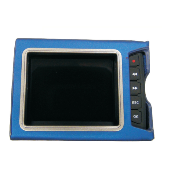
Page 5: Viewer
INTRODUCTION VIEWER LCD Display Video record button Left arrow button Right arrow button Back/return button Confirm button Microphone Speaker Power / image capture button AV / Probe input Charging indicator LED Power indicator LED AV / Probe output USB connector Lock... -
Page 6: Section 2: Operation
OPERATION POWER ON/OFF Press and hold the POWER button to power ON and OFF. The unit will vibrate when powering on and off. When powering ON, the unit will vibrate continuously if the probe is not properly connected. While the unit is powered on, the blue power indicator LED will be lit. Upon initial startup, a video test screen will briefly appear, then the display will show the image coming from the probe. -
Page 7: Storage Select
OPERATION STORAGE SELECT Use the arrow keys to highlight the Storage Select menu System Setting option, then press OK. Storage Select Display Setting Storage Info Brightness Format Language System Time Setting Default Because the unit only includes an internally installed SC card, only “SD card”... -
Page 8: Storage Info
OPERATION STORAGE INFO Use the arrow keys to highlight the Storage Info menu System Setting option, then press OK. Storage Select Display Setting Storage Info Brightness Format Language System Time Setting Default The statistics of the internal SD card will be shown, including SD Card Info total memory, memory in use, and memory remaining. -
Page 9: Format
OPERATION FORMAT Use the arrow keys to highlight the Format menu option, System Setting then press OK. Storage Select Display Setting Storage Info Brightness Format Language System Time Setting Default To exit without formatting the SD card, highlight No and Format SD Card press ESC or OK. -
Page 10: System Time Setting
OPERATION SYSTEM TIME SETTING Use the arrow keys to highlight the System Time Setting System Setting menu option, then press OK. Storage Select Display Setting This time and date will appear on the LCD display while Storage Info Brightness inspecting fiber endfaces. Format Language System Time Setting... -
Page 11: Display Output Setting
OPERATION DISPLAY OUTPUT SETTING Use the arrow keys to highlight the Display Setting menu System Setting option, then press OK. Storage Select Display Setting Storage Info Brightness Format Language System Time Setting Default For normal hand-held operations, always use the LCD Display Output Setting Output option. -
Page 12: Brightness
OPERATION BRIGHTNESS Use the arrow keys to highlight the Brightness menu System Setting option, then press OK. Storage Select Display Setting Storage Info Brightness Format Language System Time Setting Default Use the arrow keys to increase or decrease the LCD Brightness brightness. -
Page 13: Language
OPERATION LANGUAGE Use the arrow keys to highlight the Language menu option, System Setting then press OK. Storage Select Display Setting Storage Info Brightness Format Language System Time Setting Default It is highly recommended to leave this option set to English. Language Setting Default option. -
Page 14: Default
OPERATION DEFAULT Use the arrow keys to highlight the Default menu option, System Setting then press OK. Storage Select Display Setting This menu option allows the user to set the user preferences Storage Info Brightness to factory defaults. Format Language System Time Setting Default To exit without re-setting factory defaults, press ESC, or... -
Page 15: Viewing Fiber Endfaces
OUT and IN jacks on the side of the unit. Attach the appropriate probe tip according to the connector port or ferrule size that will be inspected. Several probe tip options are included with the VS-400-H. Power ON the VS-400-H. The LCD display will initially show a test pattern. -
Page 16: Saving Endface Images
OPERATION SAVING ENDFACE IMAGES Once the endface image is sufficiently focused, the user can either capture the image to a video file, or a still image file. SAVING VIDEO FILES Press the Video Record button to begin recording the video. 016/07/07 08:48:35 While recording, the RECORD icon will appear. -
Page 17: Retrieving Endface Images
OPERATION RETRIEVING ENDFACE IMAGES From the endface viewer screen, press ESC to enter the main menu screen. By default, the Check Up option will be selected. Press the arrow keys to highlight the Playback option, then press OK. Playback Select VIDEO or PHOTO. VIDEO PHOTO Video Playback... -
Page 18: Charging The Battery
OPERATION CHARGING THE BATTERY Two re-chargeable battery packs and a battery charger are included with the VS-400-H. RE-CHARGING BATTERY PACKS To re-charge the battery packs, insert the battery pack into the charger contacts first, then press the other side down until the battery pack is fully seated. -
Page 19: Section 3: Connecting The Videoscope To Pc/Laptop
DOWNLOADING IMAGES TO PC/LAPTOP Connect the VS-400-H to a working USB port on a PC or laptop using the supplied USB cable. The VS-400-H will connect as USB storage device (similar to a USB flash drive) and will be assigned a drive letter.
Need help?
Do you have a question about the VS-400-H and is the answer not in the manual?
Questions and answers