Table of Contents
Advertisement
Quick Links
Advertisement
Table of Contents

Subscribe to Our Youtube Channel
Related Manuals for W&H Osmo

Summary of Contents for W&H Osmo
- Page 1 Instructions for use Osmo - ENG - Rev 00...
-
Page 2: Table Of Contents
Table of contents W&H symbols ..................Warranty . -
Page 3: W&H Symbols
Live electric parts inside the unit. Do not dispose of Don't drink the water Filter cartridge with normal waste produced by Osmo Lock/Unlock position Resin filter Carbon filter cartridge cartridge... -
Page 4: Warranty
WORKS/REPAIRS DURING THE WARRANTY PERIOD For work or repairs under warranty the customer must contact the supplier. See the warranty certificate, delivered with every Osmo, for the warranty period and exclusions. WARRANTY RESTRICTIONS The warranty covers replacement or repair of the components recognized as being unsuitable due to manufacturing defects, inclusive of the necessary labor. -
Page 5: General Information And Safety Advice
Treated water is the ideal solution for professional use and delivery since the exclusive filtration system forms a safety barrier against different pollutants in groundwater. The reverse osmosis purification system Osmo is made with the highest quality components and was designed and configured for professional use. - Page 6 • in the event of a fault or poor operation, switch off the Osmo and do not tamper with it. Contact an authorized technician for any intervention; if parts of the reverse osmosis purifying system are replaced, for maintenance or due to a fault, by an unauthorized technician, make sure...
- Page 7 • Only use genuine manufacturer spare parts dedicated for this product; • Do not drink the water produced by Osmo; • Do not block or crush the inlet or outlet pipes of the equipment or the sterilizer; • If the water dispenser is not used (manual filling) we recommend closing the spiral tube’s connecting tap;...
-
Page 8: Storage
2. Storage The packaged equipment must be stored in a dry place (without condensate), protected against bad weather. The permitted temperature is +5 °C ÷ 35 °C. Even if carefully packaged and protected, the system must be considered and handled as fragile material. On receipt, check the external conditions of the package and the equipment in it. -
Page 9: Contents Of The Packaging
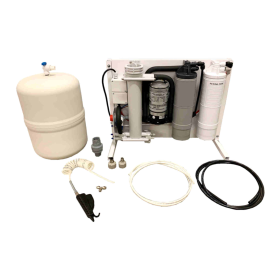
3. Contents of the packaging General notes on delivery Upon delivery of the equipment, check the condition of the package and keep it in case of future needs. Open the package and check that: • the contents correspond to the delivery note and to the list in the next page; •... - Page 10 Contents of the packaging 1. Complete osmotic subset composed of: 2 filter cartridges (resin and carbon), 1 osmotic membrane, 1 pump, 1 one-way valve, 1 pressure switch, electric system and a variety of internal and external connecting tubes (support bracket kit - optional); 2.
-
Page 11: Conditions Of Use And Period Of Use
4. Conditions of use and period of use Reverse osmosis system processing essentially consists in an adjustable reduction of fixed residue in treated water. This equipment is for the treatment of drinking water only. Input water must be drinkable according to the National and local rules and standards in force in the Country of installation. -
Page 12: Installation
5. Installation PRELIMINARY INSTALLATION INSTRUCTIONS Wall-mounted installation The water demineralizer should be fitted in a vertical position either beneath a sink or in a cabinet. For mounting, use the supplied dowels and screws. Install on the wall leaving a space of at least 10 cm from the floor or the bottom surface so that the filter cartridge can be dismantled. Overall dimensions 230 mm 520 mm... - Page 13 Installation INSTALLATION PROCEDURE Step Description Image Wall-mounted installation Install the osmotic group using the 4 supplied dowels and screws. Installation with brackets (optional) Install the brackets on the osmotic group using the 4 screws and nuts.
- Page 14 Attention: seal the thread with PTFE tape. Do not use glue nor paste as a sealant. Remove the red cap from the “IN” fitting of the Osmo and tighten the quick-connector fitting ¾“ (ø 8 mm) on it.
- Page 15 ® Connect the black tube in the fitting at the Water Block valve outlet and in the fitting “IN” of the Osmo. These are quick-connector fittings: insert the tube until it hits the back of the fitting and pull slightly to check it is correctly inserted.
- Page 16 Insert the white tube (from the fitting “TANK” of the Osmo) in the storage tank tap and tighten it with the ring nut. Connect the white tube in the fitting “OUT” of the Osmo.
- Page 17 Insert the other end of the tube from the fitting “OUT” From fitting “OUT” of the Osmo to the T-connection of the water dispenser and tighten it with the ring nut. Insert one white tube in the T-connection of the...
- Page 18 Installation Connection to: • Water dispenser • Tap (optional) Example of installation...
- Page 19 Installation EXAMPLES OF USAGE Description Image Manual use with water dispenser for manual filling of the sterilizer tank and washing of instruments. Manual usage with tap (optional).
-
Page 20: Priming
Description Image Slowly opens the water network tap and insert the Osmo mains cable into the power socket. Note: make sure there is no leakage and there are no traces of water on the bottom of the equipment. Do not operate the equipment without having opened the water supply first. -
Page 21: Use And Operation
7. Use and operation USE OF OSMO Once the system has been correctly installed and connected, the demineralizer is able to immediately supply purified and demineralized water. If the demineralized water is used to run a sterilizer, you may choose between manually filling the sterilizer tank with the water dispenser, or having it filled automatically (if the sterilizer is suitable for connection to a purified water system). -
Page 22: Maintenance
8. Maintenance Disconnect the mains plug before carrying out any maintenance. Check regularly the housing and the mains cable for damage in order to prevent electrical accidents. EXTERNAL CLEANING Switch the equipment OFF before cleaning. Clean the equipment with a damp cloth using non-abrasive and non-corrosive detergents (neutral pH value). MAINTENANCE OF THE Water Block ®... - Page 23 Maintenance REPLACEMENTE OF THE FILTER CARTRIDGES / MEMBRANE Only use genuine cartridges as they have been specifically designed for this product. The lifespan of the filter cartridges depends largely on the operating conditions and, above all, on the quality of the city water in your area. Annual cartridge replacement is recommended for average use.
- Page 24 Maintenance REPLACEMENTE OF THE FILTER CARTRIDGES Step Description Image Disconnect the electrical power supply. Close the water inlet tap and the storage tank tap. If present, release the water pressure with the use of the water dispenser or tap (if connected - optional) Turn the exhausted filter cartridge counter-clockwise and remove it.
- Page 25 Maintenance REPLACEMENTE OF THE OSMOTIC MEMBRANE Step Description Image Disconnect the electrical power supply. Close the water inlet tap and the storage tank tap. If present, release the water pressure with the use of the water dispenser or tap (if connected - optional). Using the appropriate tool, unscrew the osmotic vessel cap by turning it counter-clockwise and remove it.
- Page 26 Maintenance Step Description Image Extract the membrane with the help of pliers. Note: during this operation, water will inevitably pour out of the vessel. Insert the new membrane completely, making sure that the two o-rings are positioned correctly. Tighten the osmotic vessel cap by turning it clockwise with the appropriate tool.
-
Page 27: Water Block Safety Valve
® 9. Water Block safety valve Water Block (WB) SAFETY VALVE Indispensable device for washing machines, dishwashers and demineralizers as, under the conditions defined in the technical features herewith described, it prevents a flow of water greater than the one for which it has been set by the adjustment pointer. This avoids continuous leaking. - Page 28 ® Water Block safety valve INSTALLATION 1. The device must be installed in vertical position, flow downwards. 2. Manually screw the WB to the tap having suitable thread (3/4” gas), inserting the filter ‘E’ with its convex side facing upwards (fig.2). The WB will not operate properly if the filter is not installed correctly.
-
Page 29: Spare Parts
10. Spare parts Description Code Drawing/Image Resin filter cartridge A813028X Carbon filter cartridge A813027X Osmotic membrane A813029X Filter cartridge maintenance kit (resin + carbon filter cartridges) A813030X Complete maintenance kit A813053X (resin + carbon filter cartridges + osmotic membrane) No.2 quick-connector fittings ¾“ - tube ø 8 mm A813031X Pump 230 V A813032X... - Page 30 Spare parts Description Code Drawing/Image Storage tank A813039X Tap for storage tank A813040X O-ring for osmotic membrane (10) A813041X Resin filter cartridge head A813043X Carbon filter cartridge head A813042X Osmotic vessel A813046X L-shaped quick fitting ø 8 mm – for black tube A813047X L-shaped quick fitting ø...
- Page 31 Spare parts Description Code Drawing/Image Pressure switch A813052X Water dispenser kit A812018X Water tap kit (optional) A813044X Support bracket kit (optional) A813045X Pressure reducer ¾” x ¾” 3 bar (optional) A813025X...
-
Page 32: Troubleshooting
11. Troubleshooting FAULT TABLE When solving problems, assess and remove the possible causes in the given order. Anomaly Cause Intervention Water delivery for over 15 min Switch the equipment OFF and ON Motor alarm Large leak inside or downstream of the Repair the fault, switch the equipment OFF (the equipment does not deliver water) machine... -
Page 33: Technical Data
12. Technical data Technical data Description Operating temperature +5 °C ÷ 30 °C +5 °C ÷ 35 °C Storage temperature Protect from sunlight or other sources of heat 230 V ac, 50/60 Hz, 0.6 A Electrical power supply 115 V ac, 50/60 Hz, 1.2 A Max. -
Page 34: Authorized W&H Service Partners
13. Authorized W&H service partners A list and a map with your nearest W&H service partner are available at http://wh.com. 14. Disposal of the product The crossed out wheelie bin symbol on the equipment or its packaging indicates that the product at the end of its useful life must be collected separately from other waste. - Page 35 Notes...
- Page 36 W&H Sterilization S.r.l. Osmo ENG Instructions for Use - Rev 00 Italy, I-24060 Brusaporto (BG), via Bolgara, 2 t +39/035/66 63 000 f +39/035/50 96 988 Subject to alterations 08/01/2021 wh.com...
Need help?
Do you have a question about the Osmo and is the answer not in the manual?
Questions and answers