Table of Contents
Advertisement
Quick Links
Wireless Access Point / Client
Hardware Installation Guide
Important note:
This document and additional product information can be
downloaded using following link:
http://www.weidmueller.com
► Select Product Catalogue
Select „Active Industrial Ethernet "
Select „WLAN AP/Bridge/Client "
Select Product model
Click and expand section „Downloads "
Download needed software or documentation
Copyright 2018 Weidmüller Interface GmbH & Co. KG
Reproduction without permission is prohibited.
Basic Line
IE-WL-BL-AP-CL-EU
IE-WLT-BL-AP-CL-EU
IE-WL-BL-AP-CL-US
IE-WLT-BL-AP-CL-US
Second Edition, June 2018
2581010000/01/06.18
Copyright Notice
All rights reserved.
Advertisement
Table of Contents

Related Manuals for Weidmüller Basic Line IE-WL-BL-AP-CL-EU

Summary of Contents for Weidmüller Basic Line IE-WL-BL-AP-CL-EU
- Page 1 Wireless Access Point / Client Basic Line IE-WL-BL-AP-CL-EU IE-WLT-BL-AP-CL-EU IE-WL-BL-AP-CL-US IE-WLT-BL-AP-CL-US Hardware Installation Guide Second Edition, June 2018 2581010000/01/06.18 Important note: This document and additional product information can be downloaded using following link: http://www.weidmueller.com ► Select Product Catalogue Select „Active Industrial Ethernet “ ...
-
Page 2: Package Checklist
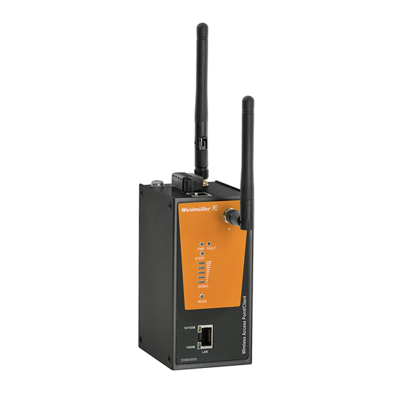
Overview Weidmüller Wi-Fi devices are ideal for applications that are hard to wire, too expensive to wire, or use mobile equipment that connects over a TCP/IP network. The devices meet the growing need for faster data transmission speeds by supporting IEEE 802.11n technology with a net data rate of up to 300 Mbps. - Page 3 Panel Layout of IE-WL(T)-BL-AP-CL-EU/US Top Panel View 1. Grounding screw (M5) 2. Terminal block for power input PWR1 and PWR2 3. RS-232 console port 4. Antenna B port 5. System LEDs: PWR, FAULT and STATE 6. LEDs for WLAN signal strength 7.
-
Page 4: Mounting Dimensions
Mounting Dimensions DIN-Rail Mounting The aluminum DIN-rail attachment plate should already be fixed to the back panel of the Wi-Fi device when you take it out of the box. If you need to reattach the DIN-rail attachment plate, make sure the stiff metal spring is situated towards the top, as shown in the figures below. -
Page 5: Wall Mounting (Optional)
Wall Mounting (optional) For some applications, you will find it convenient to mount the Wi-Fi device on the wall, as shown in the following figures. STEP 1: Remove the aluminum DIN-Rail attachment plate from the switch rear panel, and then attach the wall mount plates as shown in the diagram at the right. -
Page 6: Wiring Requirements
Wiring Requirements WARNING Safety First! Be sure to disconnect the power cord before installing and/or wiring the Wireless Access Point/Client. Calculate the maximum possible current in each power wire and common wire. Observe all electrical codes dictating the maximum current allowed for each wire size. If the current goes above the maximum ratings, the wiring could overheat, causing serious damage to your equipment. - Page 7 Grounding the Wireless Access Point/Client Grounding and wire routing help limit the effects of noise due to electromagnetic interference (EMI). Run the ground connection from the ground screw to the grounding surface prior to connecting devices. ATTENTION This product is intended to be mounted to a well-grounded mounting surface, such as a metal panel.
-
Page 8: Wiring The Redundant Power Inputs
Wiring the Redundant Power Inputs The 4-contact terminal block connector on the Wireless Access Point/Client´s top panel are used for the two DC inputs. Top and front views of the terminal block connector are shown here. STEP 1: Insert the negative/positive DC wires into the V-/V+ terminals. -
Page 9: Communication Connections
Communication Connections 10/100BaseT(X) Ethernet Port Connection The 10/100BaseT(X) port located on the Wireless Access Point/Client´s front panel is used to connect to Ethernet-enabled devices. Below we show pinouts for both MDI (NIC-type) ports and MDI-X (HUB/Switch-type) ports. MDI Port Pinouts MDI-X Port Pinouts 8-pin RJ45 Signal... -
Page 10: Led Indicators
LED Indicators The front panel of the Wireless Access Point/Client contains several LED indicators. The function of each LED is described in the table below. Color State Description Power is being supplied to either power input PWR1 and/or PWR2. Green Power is not being supplied to power input PWR1 or PWR2. -
Page 11: Specifications
Specifications WLAN Interface Standards IEEE 802.11a/b/g/n for Wireless LAN IEEE 802.11i for Wireless Security IEEE 802.3 for 10BaseT IEEE 802.3u for 100BaseT(X) IEEE 802.3ab for 1000BaseT Spread Spectrum and DSSS with DBPSK, DQPSK, CCK Modulation (typical) OFDM with BPSK, QPSK, 16QAM, 64QAM ... - Page 12 802.11n (2.4 GHz): • Typ. 23±1.5 dBm @ MCS0/8 20 MHz, • Typ. 18±1.5 dBm @ MCS7/15 20 MHz • Typ. 23±1.5 dBm @ MCS0/8 40 MHz, • Typ. 17±1.5 dBm @ MCS7/15 40 MHz 802.11a: • Typ. 23±1.5 dBm @ 6 to 24 Mbps •...
- Page 13 Protocol Support Proxy ARP, DNS, HTTP, HTTPS, IP, ICMP, SNTP, General Protocols TCP, UDP, RADIUS, SNMP, DHCP, LLDP Interface Default Antennas 2x dual-band omni-directional antennas, 2 dBi, RP-SMA (male) Connector for 2x RP-SMA (female) External Antennas LAN Ports 1x RJ 45, 10/100/1000BaseT(X) auto negotiation speed, F/H duplex mode and auto MDI/MDI-X connection Console Port...
- Page 14 ATTENTION The Weidmüller WLAN device is NOT a portable mobile device and should be located at least 20 cm away from the human body. The Weidmüller WLAN device is NOT designed for the general public. A well-trained technician is required to deploy the Weidmüller WLAN device units and safely establish a wireless network.
- Page 15 WARNING • This equipment is intended to be used in a Restricted Access Location, such as a dedicated computer room where only authorized service personnel or users can gain access. Such personnel must be instructed about the fact that the metal chassis of the equipment is extremely hot and may cause burns.
Need help?
Do you have a question about the Basic Line IE-WL-BL-AP-CL-EU and is the answer not in the manual?
Questions and answers