
Related Manuals for matev SPR-HM-80

Summary of Contents for matev SPR-HM-80
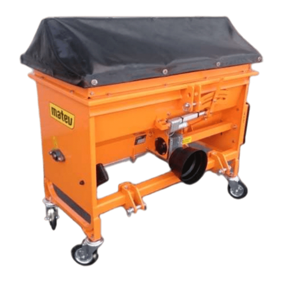
- Page 1 GmbH Nürnberger Str. 50 90579 Langenzenn, Germany T +49 9101 9087 -0 F +49 9101 9087 -20 info@matev.eu www.matev.eu Original Operating Manual Box spreader SPR – HM – 80 – 100 – 120 Version: 02/2021...
-
Page 2: Table Of Contents
Contents Table of contents About this operating manual ..................3 Safety ........................... 4 Intended use ......................... 4 Qualifications of personnel .................... 4 General safety notices ....................4 Special safety notices ....................5 Delivery and transport ....................7 Lifting the spreader off of the pallet ................7 Long-distance transport .................... -
Page 3: About This Operating Manual
About this operating manual Dear customer! Congratulations on your purchase of this box spreader and thank you for choosing matev. Carefully read this entire operating manual before using the box spreader the first time. Keep this operating manual where it is easily accessible. This will enable you to refer to important information and handling instructions as needed. -
Page 4: Safety
Safety Safety Note Must be read!!! Guidelines and instructions that you must comply with are presented in this section. Intended use The spreader should only be mounted on tractors with sufficient power axle load. The prescribed ballast for the tractor and the specified maximum axle load must be complied with. -
Page 5: Special Safety Notices
Safety Comply with these safety notices to ensure safe operation and to save work time and costs. • In addition to the instructions in this operating manual, also comply with the generally valid safety and accident prevention regulations! Young persons under the age of 16 are not allowed to operate the implement! •... - Page 6 Safety Attention! Injuries can occur due to improper operation. The implement can be damaged. Read the operating manual all the way through. Comply with the safety instructions. Danger due to thrown-out parts when the engine is running – maintain a safety distance.
-
Page 7: Delivery And Transport
Delivery and transport Delivery and transport The spreader is delivered lashed on a pallet. Lifting the spreader off of the pallet Remove the protective packaging and the transport safeguard. Lift the spreader off of the pallet using suitable equipment, such as a crane or forklift, and set it down. -
Page 8: Installation
• Cat 1 • Cat 1-N • Cat 2 (not possible with SPR-HM-80) Mount the spreader in the tractor’s rear three-point linkage. Make sure to use the correct connecting points corresponding to the three-point linkage. Page 8... -
Page 9: Mechanical Drive
Installation There are two attachment points for the upper link. • Upper point is for Cat 2 • Lower point is for Cat 1 and Cat 1N Fig. 1: Mounting categories The mount for the tractor’s lower link is width-adjustable and likewise is equipped with two attachment points. -
Page 10: Fig. 2: Mark The Cutting Point Fig. 3: Sawing The Universal Joint Shaft To Length
Installation 2. Mount the one end of the universal joint shaft on the tractor. 3. Mount the other end of the universal joint shaft on the implement. 4. In the shortest work position, mark the piece that will be sawn off on one half of the universal joint shaft. -
Page 11: Drive Kit, Hydraulic
Installation 1. Connect the counter-piece of the shaft with the implement and secure this with the screw included in the scope of delivery. 2. Press the locking disk that is on the outer side and keep it depressed. 3. Slide the splined shaft onto the splined shaft of the PTO shaft. 4. -
Page 12: Manual Dosing Flap Actuation
Installation Manual dosing flap actuation The dosing flap can be moved by hand. The maximum opening can be defined by setting the locking mechanism. Hydraulic dosing flap actuation The dosing flap can be moved hydraulically by means of a hydraulic cylinder. The maximum opening can be defined by setting the locking mechanism. -
Page 13: Lighting
Installation Lighting To operate the lighting system the plug-in connector of the spreader must be connected to the trailer socket on the tractor. Before each use, inspect the lighting system to ensure that it is functioning properly. Depending on the width, the lights are mounted as shown in the following three figures. Fig. -
Page 14: Work Light
Installation The cable for the lights is routed in the channel and fastened with cable ties. Fig. 14: Routing of cables An optional hoop guard can be mounted over the lights. Work light The work light with mud guard can be connected only in combination with the lighting system. -
Page 15: Volume Expansion And Tarpaulin
Installation 4.10 Volume expansion and tarpaulin The volume of the box spreader can be expanded by means of add-on sections. The optional folding tarpaulin can be mounted without add-on sections or on top of the add-on sections. Make allowance for the axle loads of the tractor! No more than two add-on sections can be mounted on one spreader. -
Page 16: Mounting The Seed Rail
Installation 4.12 Mounting the seed rail The seed rail is mounted on the rigid part of the dosing rail as shown in the figures. Fig. 18: Screw-on point, rigid part of dosing rail Fig. 19: Seed rail mounted Fig. 20: Seed rail mounted 4.13 Broom and shovel holder The broom and shovel holder is mounted as shown in the figure. -
Page 17: Operation
Operation Fig. 21: Broom and shovel holder Fig. 22: Broom and shovel lock Operation Danger! Severe injury to the operator or third parties occurs. The load distribution on the trailer changes due to the attached spreader. Steering and braking capability, as well as tilt behavior are influenced. Initiate countermeasures - ensure sufficient front wheel ballast! Danger! Severe injury to the operator or third parties occurs. -
Page 18: Inspections Before Putting Into Operation
Operation Fill the spreader no higher than the edge of the box spreader or the volume expansion add-on sections. Note! Do not exceed the maximum rated load. If the rated load is exceeded this will void the warranty. Different specific weights occur depending on the status of the spread material (wet or dry). -
Page 19: Lighting
Operation Danger! Severe injury to the operator or third parties occurs. Never reach into the area of the agitator, spreader disc and vanes while they are rotating. Switch off the tractor and remove the ignition key before reaching into the area of the vanes. Attention! Danger of crushing due to moving parts. -
Page 20: Troubleshooting
Troubleshooting Troubleshooting If the spread pattern is not satisfactory, this may be due to the following reasons: • Inconsistent properties of the spread material: different density, grain form or moisture content • Clotting of the spread material • Spread material is blown away by strong wind •... -
Page 21: Maintenance
Maintenance Attention! Properly reattach all protective devices that have been dismounted after executing the maintenance tasks. Note! • After the first 20 hours of operation check all screw and bolt connections. • Subject the implement to regular maintenance. • Use lubricating grease to lubricate the moving parts. Maintenance The spreader must be cleaned and the container emptied after each use, as well as at the start and end of the season. -
Page 22: Fig. 24: Pedestal Bearing On Left In Direction Of Travel
Maintenance 7.2.2 Lubricating schedule To lubricate the device as specified in the maintenance schedule, proceed as follows: • Lubricate the pedestal bearing on the left in direction of travel Fig. 24: Pedestal bearing on left in direction of travel • Lubricate the two pedestal bearings and the chain in the chain housing. -
Page 23: Fig. 27: Regreasing The Spread Rail
Maintenance Fig. 27: Regreasing the spread rail • The universal joint shaft must be greased. Fig. 28: Universal joint shaft 7.2.3 Replacing agitator fingers / agitator shaft The agitator fingers are wear parts and must be replaced if they are worn. Attention! Remove the key from the ignition before replacing the agitator fingers. -
Page 24: Fig. 29: Loosening The Shaft
Maintenance Fig. 29: Loosening the shaft Unscrew the cover from the chain housing, relax the chain tension and remove the chain. Remove the large chain wheel and the chain tensioning wheel Fig. 30: Opening the chain housing Remove the pedestal bearing and the plate behind the pedestal bearing Pull out the agitator shaft Fig. -
Page 25: Repair
Fig. 34: Agitator shaft in box spreader Repair If there are faults, problems, or other indications of malfunction, contact your sales consultant or contact the manufacturer directly: matev GmbH Nürnberger Str. 50 90579 Langenzenn Tel.: (Switchboard): +49 9101/90 87-0 Enter the article number and the chassis number here. -
Page 26: Guarantee
Take the parts to the collection points for residual waste, special waste, or recycle them depending on material. matev GmbH does not provide any disposal services. Guarantee The General Terms & Conditions of matev GmbH provide information on the guarantee conditions. matev GmbH Nürnberger Str. 50... -
Page 27: Accessories
Technical data and accessories 10.2 Accessories Accessories Central lubrication system Wheel set Cover tarp Add-on section for volume expansion Lighting Work light Holder for broom and shovel Fig. 36: Accessories Page 27... -
Page 28: List Of Illustrations
List of illustrations List of illustrations Fig. 1: Mounting categories ........................... 9 Fig. 2: Mark the cutting point Fig. 3: Sawing the universal joint shaft to length ........10 Fig. 4: Sawing off the profile tube Fig. 5: Deburring of the cut edges ..........10 Fig. -
Page 29: Ec Declaration Of Conformity
EC Declaration of Conformity for a machine to confirm compliance with the Machinery Directive 2006/42/EC and with the statutory regulations issued for the implementation of the Machinery Directive. The manufacturer matev GmbH Nuremberg Str.50 90579 Langenzenn, Germany declares that the machine...
Need help?
Do you have a question about the SPR-HM-80 and is the answer not in the manual?
Questions and answers