Table of Contents
Advertisement
Available languages
Available languages
Quick Links
Version 1.0
Published February 2021
Copyright©2021 ASRock INC. All rights reserved.
Copyright Notice:
No part of this documentation may be reproduced, transcribed, transmitted, or
translated in any language, in any form or by any means, except duplication of
documentation by the purchaser for backup purpose, without written consent of
ASRock Inc.
Products and corporate names appearing in this documentation may or may not
be registered trademarks or copyrights of their respective companies, and are used
only for identification or explanation and to the owners' benefit, without intent to
infringe.
Disclaimer:
Specifications and information contained in this documentation are furnished for
informational use only and subject to change without notice, and should not be
constructed as a commitment by ASRock. ASRock assumes no responsibility for
any errors or omissions that may appear in this documentation.
With respect to the contents of this documentation, ASRock does not provide
warranty of any kind, either expressed or implied, including but not limited to
the implied warranties or conditions of merchantability or fitness for a particular
purpose.
In no event shall ASRock, its directors, officers, employees, or agents be liable for
any indirect, special, incidental, or consequential damages (including damages for
loss of profits, loss of business, loss of data, interruption of business and the like),
even if ASRock has been advised of the possibility of such damages arising from any
defect or error in the documentation or product.
This device complies with Part 15 of the FCC Rules. Operation is subject to the following
two conditions:
(1) this device may not cause harmful interference, and
(2) this device must accept any interference received, including interference that
may cause undesired operation.
CALIFORNIA, USA ONLY
The Lithium battery adopted on this motherboard contains Perchlorate, a toxic substance
controlled in Perchlorate Best Management Practices (BMP) regulations passed by the
California Legislature. When you discard the Lithium battery in California, USA, please
follow the related regulations in advance.
"Perchlorate Material-special handling may apply, see www.dtsc.ca.gov/hazardouswaste/
perchlorate"
ASRock Website: http://www.asrock.com
Advertisement
Table of Contents

Related Manuals for ASROCK H570 Steel Legend


Summary of Contents for ASROCK H570 Steel Legend
- Page 1 (including damages for loss of profits, loss of business, loss of data, interruption of business and the like), even if ASRock has been advised of the possibility of such damages arising from any defect or error in the documentation or product.
- Page 2 If you require assistance please call ASRock Tel : +886-2-28965588 ext.123 (Standard International call charges apply) The terms HDMI®...
- Page 3 ES OF ANY KIND WHETHER UNDER THIS AGREEMENT OR OTHERWISE, EVEN IF INTEL HAS BEEN ADVISED OF THE POSSIBILITY OF SUCH DAMAGES. LICENSE TO USE COMMENTS AND SUGGESTIONS. This Agreement does NOT obligate Licensee to provide Intel with comments or suggestions regarding the Software. However, if Licensee provides Intel with comments or suggestions for the modification, correction, improvement or enhancement of (a) the Software or (b) Intel products or processes that work with the Software, Licensee grants to Intel a non-exclusive, worldwide,...
-
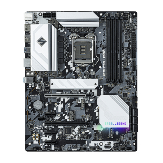
Page 5: Motherboard Layout
H570 Steel Legend Motherboard Layout CPU_FAN2/WP CHA_FAN3/WP ATX12V1 ATX12V2 CPU_FAN1 USB 3.2 Gen2 T:USB31_TA_1 B: USB31_TC_1 USB 3.2 Gen1 Top: T: USB3_1 RJ-45 B: USB3_2 CHA_FAN1/WP CHA_FAN2/WP PCIE1 CMOS Battery Intel H570 PCIE2 T B1 M2_WIFI_CT1 PCIE3 RoHS AUDIO CODEC... - Page 6 No. Description ATX 12V Power Connector (ATX12V1) ATX 12V Power Connector (ATX12V2) CPU Fan Connector (CPU_FAN1) 2 x 288-pin DDR4 DIMM Slots (DDR4_A1, DDR4_B1) 2 x 288-pin DDR4 DIMM Slots (DDR4_A2, DDR4_B2) CPU/Water Pump Fan Connector (CPU_FAN2/WP) RGB LED Header (RGB_LED2) Addressable LED Header (ADDR_LED2) Chassis/Water Pump Fan Connector (CHA_FAN3/WP) ATX Power Connector (ATXPWR1)
- Page 7 H570 Steel Legend I/O Panel No. Description No. Description USB 2.0 Ports (USB_1_2) USB 3.2 Gen1 Ports (USB3_1_2) USB 3.2 Gen2 Type-A Port USB 3.2 Gen2 Type-C Port (USB31_TA_1) (USB31_TC_1) 2.5G LAN RJ-45 Port* DisplayPort 1.4 Line In (Light Blue)**...
-
Page 8: Chapter 1 Introduction
ASRock’s website without further notice. If you require technical support related to this motherboard, please visit our website for specific information about the model you are using. You may find the latest VGA cards and CPU support list on ASRock’s website as well. ASRock website http://www.asrock.com. -
Page 9: Specifications
Gen Intel® Core (i9/i7) support DDR4 up to 2933; Core (i5/i3), Pentium® and Celeron® support DDR4 up to 2666. * Please refer to Memory Support List on ASRock's website for more information. (http://www.asrock.com/) • Supports ECC UDIMM memory modules (operate in non- ECC mode) • Max. - Page 10 • 3 x PCI Express 3.0 x1 Slots • Supports AMD Quad CrossFireX and CrossFireX • 1 x M.2 Socket (Key E), supports type 2230 WiFi/BT module and Intel® CNVi (Integrated WiFi/BT) Graphics * Intel® UHD Graphics Built-in Visuals and the VGA outputs can be supported only with processors which are GPU integrated.
- Page 11 H570 Steel Legend • 2.5 Gigabit LAN 10/100/1000/2500 Mb/s • Dragon RTL8125BG • Supports Dragon 2.5G LAN Software - Smart Auto Adjust Bandwidth Control - Visual User Friendly UI - Visual Network Usage Statistics - Optimized Default Setting for Game, Browser, and...
- Page 12 Express module up to Gen3 x4 (32 Gb/s)** ** Supports Intel® Optane Technology ** Supports NVMe SSD as boot disks ** Supports ASRock U.2 Kit Connector • 1 x SPI TPM Header • 1 x Power LED and Speaker Header • 2 x RGB LED Headers...
-
Page 13: Hardware Monitor
• ErP/EuP ready (ErP/EuP ready power supply is required) * For detailed product information, please visit our website: http://www.asrock.com Please realize that there is a certain risk involved with overclocking, including adjusting the setting in the BIOS, applying Untied Overclocking Technology, or using third-party overclocking tools. -
Page 14: Chapter 2 Installation
Chapter 2 Installation This is an ATX form factor motherboard. Before you install the motherboard, study the configuration of your chassis to ensure that the motherboard fits into it. Pre-installation Precautions Take note of the following precautions before you install motherboard components or change any motherboard settings. -
Page 15: Installing The Cpu
H570 Steel Legend 2.1 Installing the CPU 1. Before you insert the 1200-Pin CPU into the socket, please check if the PnP cap is on the socket, if the CPU surface is unclean, or if there are any bent pins in the socket. Do not force to insert the CPU into the socket if above situation is found. - Page 17 H570 Steel Legend Please save and replace the cover if the processor is removed. The cover must be placed if you wish to return the motherboard for after service.
-
Page 18: Installing The Cpu Fan And Heatsink
2.2 Installing the CPU Fan and Heatsink... -
Page 19: Installing Memory Modules (Dimm)
H570 Steel Legend 2.3 Installing Memory Modules (DIMM) This motherboard provides four 288-pin DDR4 (Double Data Rate 4) DIMM slots, and supports Dual Channel Memory Technology. 1. For dual channel configuration, you always need to install identical (the same brand, speed, size and chip-type) DDR4 DIMM pairs. -
Page 21: Expansion Slots (Pci Express Slots)
H570 Steel Legend 2.4 Expansion Slots (PCI Express Slots) There are 5 PCI Express slots on the motherboard. Before installing an expansion card, please make sure that the power supply is switched off or the power cord is unplugged. Please read the documentation of the expansion card and make necessary hardware settings for the card before you start the installation. - Page 22 PCIe Slot Configurations Gen Intel® Core Processors PCIE1 PCIE3 Single Graphics Card Gen4x16 Two Graphics Cards in Gen4x16 Gen3x4 CrossFireX Mode Gen Intel® Core Processors PCIE1 PCIE3 Single Graphics Card Gen3x16 Two Graphics Cards in Gen3x16 Gen3x4 CrossFireX Mode For a better thermal environment, please connect a chassis fan to the motherboard’s chassis fan connector (CHA_FAN1/WP, CHA_FAN2/WP, CHA_FAN3/WP or CHA_FAN4/WP) when using multiple graphics cards.
-
Page 23: Jumpers Setup
H570 Steel Legend 2.5 Jumpers Setup The illustration shows how jumpers are setup. When the jumper cap is placed on the pins, the jumper is “Short”. If no jumper cap is placed on the pins, the jumper is “Open”. Clear CMOS Jumper... -
Page 24: Onboard Headers And Connectors
2.6 Onboard Headers and Connectors Onboard headers and connectors are NOT jumpers. Do NOT place jumper caps over these headers and connectors. Placing jumper caps over the headers and connectors will cause permanent damage to the motherboard. System Panel Header Connect the power button, PLED+ PLED-... - Page 25 H570 Steel Legend Power LED and Speaker Please connect the SPEAKER DUMMY Header chassis power LED and DUMMY (7-pin SPK_PLED1) the chassis speaker to this (see p.1, No. 20) header. PLED+ PLED+ PLED- Serial ATA3 Connectors These six SATA3 Right-Angle:...
- Page 26 USB 3.2 Gen1 Headers There are two headers on Vbus Vbus Vbus IntA_PB_SSRX- Vertical: this motherboard. Each IntA_PB_SSRX+ IntA_PA_SSRX- (19-pin USB3_3_4) USB 3.2 Gen1 header can IntA_PA_SSRX+ IntA_PB_SSTX- (see p.1, No. 11) support two ports. IntA_PA_SSTX- IntA_PB_SSTX+ IntA_PA_SSTX+ IntA_PB_D- IntA_PA_D- IntA_PB_D+ IntA_PA_D+ Dummy...
- Page 27 H570 Steel Legend Chassis/Water Pump Fan This motherboard provides Connectors four 4-Pin water cooling (4-pin CHA_FAN1/WP) chassis fan connectors. If FAN_VOLTAGE (see p.1, No. 12) you plan to connect a 3-Pin FAN_SPEED FAN_SPEED_CONTROL (4-pin CHA_FAN2/WP) chassis water cooler fan, (see p.1, No. 29) please connect it to Pin 1-3.
- Page 28 ATX 12V Power This motherboard provides Connector an 8-pin ATX 12V power (8-pin ATX12V1) connector. To use a 4-pin (see p.1, No. 1) ATX power supply, please plug it along Pin 1 and Pin *Warning: Please make sure that the power cable connected is for the CPU and not the graphics card.
- Page 29 H570 Steel Legend SPI TPM Header This connector supports SPI SPI_DQ3 +3.3V (13-pin SPI_TPM_J1) Trusted Platform Module (TPM) TPM_Present (see p.1, No. 21) SPI_MOSI system, which can securely RST# store keys, digital certificates, TPM_PIRQ passwords, and data. A TPM system also helps enhance...
- Page 30 2.7 M.2 WiFi/BT Module and Intel® CNVi (Integrated WiFi/BT) Installation Guide The M.2, also known as the Next Generation Form Factor (NGFF), is a small size and versatile card edge connector that aims to replace mPCIe and mSATA. The M.2 Socket (Key E) supports type 2230 WiFi/BT module and Intel®...
- Page 31 H570 Steel Legend Step 3 Gently insert the WiFi/BT module or Intel® CNVi (Integrated WiFi/ BT) into the M.2 slot. Please be aware that the module only fits in one orientation. Step 4 Tighten the screw with a screwdriver to secure the module into place.
- Page 32 2.8 M.2_SSD (NGFF) Module Installation Guide (M2_1) The M.2, also known as the Next Generation Form Factor (NGFF), is a small size and versatile card edge connector that aims to replace mPCIe and mSATA. The Hyper M.2 Socket (M2_1) supports M Key type 2260/2280 M.2 PCI Express module up to Gen4x4 (64 Gb/s) (Only supported with 11 Gen Intel®...
- Page 33 H570 Steel Legend Step 4 Prepare the M.2 standoff that comes with the package. Then hand tighten the standoff into the desired nut location on the motherboard. Align and gently insert the M.2 (NGFF) SSD module into the M.2 slot. Please be aware that the M.2 (NGFF) SSD...
- Page 34 XP941-512G (MZHPU512HCGL) SanDisk PCIe SD6PP4M-128G SanDisk PCIe SD6PP4M-256G TEAM PCIe3 x4 TM8FP2240G0C101 TEAM PCIe3 x4 TM8FP2480GC110 PCIe3 x4 WDS256G1X0C-00ENX0 (NVME) PCIe3 x4 WDS512G1X0C-00ENX0 (NVME) For the latest updates of M.2_SSD (NFGG) module support list, please visit our website for details: http://www.asrock.com...
- Page 35 H570 Steel Legend 2.9 M.2_SSD (NGFF) Module Installation Guide (M2_2) The M.2, also known as the Next Generation Form Factor (NGFF), is a small size and versatile card edge connector that aims to replace mPCIe and mSATA. The Ultra M.2 Socket (M2_2) supports M Key type 2260/2280 M.2 SATA3 6.0 Gb/s module and M.2 PCI...
- Page 36 Step 3 Move the standoff based on the module type and length. The standoff is placed at the nut location B by default. Skip Step 3 and 4 and go straight to Step 5 if you are going to use the default nut. Otherwise, release the standoff by hand.
- Page 37 H570 Steel Legend M.2_SSD (NGFF) Module Support List (M2_2) Vendor Interface ADATA SATA3 AXNS330E-32GM-B ADATA SATA3 AXNS381E-128GM-B ADATA SATA3 AXNS381E-256GM-B ADATA SATA3 ASU800NS38-256GT-C ADATA SATA3 ASU800NS38-512GT-C ADATA PCIe3 x4 ASX7000NP-128GT-C ADATA PCIe3 x4 ASX8000NP-256GM-C ADATA PCIe3 x4 ASX7000NP-256GT-C ADATA PCIe3 x4...
- Page 38 SATA3 VLM100-120G-2280B-RD V-Color SATA3 VLM100-240G-2280RGB V-Color SATA3 VSM100-240G-2280 V-Color SATA3 VLM100-240G-2280B-RD SATA3 WDS100T1B0B-00AS40 SATA3 WDS240G1G0B-00RC30 PCIe3 x4 WDS256G1X0C-00ENX0 (NVME) PCIe3 x4 WDS512G1X0C-00ENX0 (NVME) For the latest updates of M.2_SSD (NFGG) module support list, please visit our website for details: http://www.asrock.com...
- Page 39 H570 Steel Legend 2.10 M.2_SSD (NGFF) Module Installation Guide (M2_3) The M.2, also known as the Next Generation Form Factor (NGFF), is a small size and versatile card edge connector that aims to replace mPCIe and mSATA. The Ultra M.2 Socket (M2_3) supports M Key type 2260/2280/22110 M.2 SATA3 6.0 Gb/s module and M.2...
- Page 40 Step 3 Move the standoff based on the module type and length. The standoff is placed at the nut location B by default. Skip Step 3 and 4 and go straight to Step 5 if you are going to use the default nut. Otherwise, release the standoff by hand.
- Page 41 H570 Steel Legend M.2_SSD (NGFF) Module Support List (M2_3) Vendor Interface ADATA SATA3 AXNS330E-32GM-B ADATA SATA3 AXNS381E-128GM-B ADATA SATA3 AXNS381E-256GM-B ADATA SATA3 ASU800NS38-256GT-C ADATA SATA3 ASU800NS38-512GT-C ADATA PCIe3 x4 ASX7000NP-128GT-C ADATA PCIe3 x4 ASX8000NP-256GM-C ADATA PCIe3 x4 ASX7000NP-256GT-C ADATA PCIe3 x4...
- Page 42 SATA3 VLM100-120G-2280B-RD V-Color SATA3 VLM100-240G-2280RGB V-Color SATA3 VSM100-240G-2280 V-Color SATA3 VLM100-240G-2280B-RD SATA3 WDS100T1B0B-00AS40 SATA3 WDS240G1G0B-00RC30 PCIe3 x4 WDS256G1X0C-00ENX0 (NVME) PCIe3 x4 WDS512G1X0C-00ENX0 (NVME) For the latest updates of M.2_SSD (NFGG) module support list, please visit our website for details: http://www.asrock.com...
- Page 43 H570 Steel Legend 2.11 ASRock Polychrome SYNC ASRock Polychrome SYNC is a lighting control utility specifically designed for unique indi- viduals with sophisticated tastes to build their own stylish colorful lighting system. Simply by connecting the LED strip, you can customize various lighting schemes and patterns, including Static, Breathing, Strobe, Cycling, Music, Wave and more.
- Page 44 Connecting the Addressable RGB LED Strip Connect your Addressable RGB LED strips to the Addressable LED Headers (ADDR_LED1 / ADDR_LED2) on the motherboard. ADDR_LED2 ADDR_LED1 DO_ADDR VOUT 1. Never install the RGB LED cable in the wrong orientation; otherwise, the cable may be damaged.
- Page 45 ASRock Polychrome SYNC Utility Now you can adjust the RGB LED color through the ASRock Polychrome SYNC Utility. Download this utility from the ASRock Live Update & APP Shop and start coloring your PC style your way! Drag the tab to customize your preference.
- Page 46 1 Einleitung Vielen Dank, dass Sie sich für das ASRock H570 Steel Legend entschieden haben – ein zu- verlässiges Motherboard, das konsequent unter der strengen Qualitätskontrolle von ASRock hergestellt wurde. Es liefert ausgezeichnete Leistung mit robustem Design, das ASRock Streben nach Qualität und Beständigkeit erfüllt.
-
Page 47: Technische Daten
H570 Steel Legend 1.2 Technische Daten Plattform • ATX-Formfaktor • Feststoffkondensator-Design Prozessor • Unterstützt Intel® Core -Prozessoren der 10. Generation und Intel® Core -Prozessoren der 11. Generation (LGA1200) • Digi Power design • 8-Leistungsphasendesign • Unterstützt Intel® Turbo Boost Max Technology 3.0 Chipsatz • Intel®... - Page 48 • 1 x M.2-Sockel (Key E), unterstützt Typ-2230-Wi-Fi-/-BT-Modul und Intel® CNVi (WLAN/BT integriert) Grafikkarte * Integrierte Intel® UHD Graphics-Visualisierung und VGA- Ausgänge können nur mit Prozessoren unterstützt werden, die GPU- integriert sind. • 11. Generation Intel® Core -Prozessoren unterstützen Intel® X Graphics Architecture (Gen.
- Page 49 H570 Steel Legend • Unterstützt Wake-On-LAN • Unterstützt Schutz gegen Blitzschlag/elektrostatische Entladung • Unterstützt energieeffizientes Ethernet 802.3az • Unterstützt PXE Rückblende, • 1 x PS/2-Maus-/Tastaturanschluss • 1 x HDMI-Port • 1 x DisplayPort 1.4 • 1 x USB-3.2-Gen2-Type-A-Port (10 Gb/s) (ReDriver) (unterstützt Schutz gegen elektrostatische Entladung) • 1 x USB-3.2-Gen2-Type-C-Port (10 Gb/s) (ReDriver) (unterstützt...
- Page 50 • 1 x 4-poliger 12-V-Netzanschluss (hochdichter Netzanschluss) • 1 x Audioanschluss an Frontblende • 1 x Thunderbolt Erweiterungskartenanschluss (5-polig) (unterstützt ASRock Thunderbolt 4 AIC-Karten) • 2 x USB 2.0-Stiftleisten (unterstützt 4 USB 2.0-Ports) (unterstützt Schutz gegen elektrostatische Entladung) • 2 x USB 3.2 Gen1-Stiftleiste (unterstützt vier USB 3.2 Gen1- Ports) (ASMedia ASM1074-Hub) (unterstützt Schutz gegen...
- Page 51 Zertifizie- rungen • ErP/EuP ready (ErP/EuP ready-Netzteil erforderlich) * Detaillierte Produktinformationen finden Sie auf unserer Webseite: http://www.asrock.com Bitte beachten Sie, dass mit einer Übertaktung, zu der die Anpassung von BIOS- Einstellungen, die Anwendung der Untied Overclocking Technology oder die Nutzung von Übertaktungswerkzeugen von Drittanbietern zählen, bestimmte Risiken verbunden...
- Page 52 1.3 Jumpereinstellung Die Abbildung zeigt, wie die Jumper eingestellt werden. Wenn die Jumper-Kappe auf den Kontakten angebracht ist, ist der Jumper „kurzgeschlossen“. Wenn keine Jumper-Kappe auf den Kontakten angebracht ist, ist der Jumper „offen“. CMOS-löschen-Jumper (CLRMOS1) 2-pin Jumper (siehe S. 1, Nr. 22) CLRMOS1 ermöglicht Ihnen die Löschung der Daten im CMOS.
- Page 53 H570 Steel Legend 1.4 Integrierte Stiftleisten und Anschlüsse Integrierte Stiftleisten und Anschlüsse sind KEINE Jumper. Bringen Sie KEINE Jumper- Kappen an diesen Stiftleisten und Anschlüssen an. Durch Anbringen von Jumper-Kappen an diesen Stiftleisten und Anschlüssen können Sie das Motherboard dauerhaft beschädi- gen.
- Page 54 Betrieb-LED- und Bitte verbinden Sie die Betrieb- SPEAKER Lautsprecher-Stiftleiste LED des Gehäuses und den DUMMY DUMMY (7-polig, SPK_PLED1) Gehäuselautsprecher mit dieser (siehe S. 1, Nr. 20) Stiftleiste. PLED+ PLED+ PLED- Serial-ATA-III-Anschlüsse Diese sechs SATA-III-Anschlüsse Winkel rechts: unterstützen SATA-Datenkabel für (SATA3_0: interne Speichergeräte mit einer siehe S.
- Page 55 H570 Steel Legend USB 3.2 Gen1-Stiftleisten Es gibt zwei Stiftleisten an Vbus Vbus Vbus IntA_PB_SSRX- Vertikal: diesem Motherboard. Jede USB IntA_PB_SSRX+ IntA_PA_SSRX- (19-polig, USB3_3_4) 3.2 Gen1-Stiftleiste kann zwei IntA_PA_SSRX+ IntA_PB_SSTX- (siehe S. 1, Nr. 11) Ports unterstützen. IntA_PA_SSTX- IntA_PB_SSTX+ IntA_PA_SSTX+...
- Page 56 Gehäuse-/ Dieses Motherboard bietet Wasserpumpen- vier 4-polige Wasserkühlung- Lüfteranschlusse Gehäuselüfteranschlüsse Falls FAN_VOLTAGE (4-polig, CHA_FAN1/ Sie einen 3-poligen Gehäuse- FAN_SPEED FAN_SPEED_CONTROL Wasserkühlerlüfter anschließen (siehe S. 1, Nr. 12) möchten, verbinden Sie ihn bitte (4-polig, CHA_FAN2/ mit Kontakt 1 bis 3. (siehe S. 1, Nr. 29) (4-polig, CHA_FAN3/ (siehe S.
- Page 57 H570 Steel Legend ATX-12-V- Dieses Motherboard bietet Netzanschluss einen 8-poligen ATX-12-V- (8-polig, ATX12V1) Netzanschluss. Bitte schließen (siehe S. 1, Nr. 1) Sie es zur Nutzung eines 4-poligen ATX-Netzteils entlang Kontakt 1 und Kontakt 5 an. *Warnung: Bitte stellen Sie sicher, dass das Stromkabel...
- Page 58 SPI-TPM-Stiftleiste Dieser Anschluss unterstützt das SPI_DQ3 +3.3V SPI Trusted Platform Module- (13-polig, SPI_TPM_J1) TPM_Present (TPM) System, das Schlüssel, (siehe S. 1, Nr. 21) SPI_MOSI RST# digitale Zertifikate, Kennwörter TPM_PIRQ und Daten sicher aufbewahren kann. Ein TPM-System hilft zu- dem bei der Stärkung der Netz- SPI_TPM_CS# werksicherheit, schützt digitale RSMRST#...
-
Page 59: Contenu De L'emballage
H570 Steel Legend 1 Introduction Nous vous remercions d’avoir acheté cette carte mère ASRock H570 Steel Legend, une carte mère fiable fabriquée conformément au contrôle de qualité rigoureux et constant appliqué par ASRock. Fidèle à son engagement de qualité et de durabilité, ASRock vous garantit une carte mère de conception robuste aux performances élevées. -
Page 60: Spécifications
(i5/i3), Pentium® et Celeron® prennent en charge DDR4 jusqu’à 2666. * Veuillez consulter la liste de prise en charge des mémoires sur le site Web d'ASRock pour de plus amples informations. (http://www. asrock.com/) • Prend en charge les modules mémoire UDIMM ECC (fonctionne en mode non-ECC) • Capacité... - Page 61 H570 Steel Legend • 3 x fentes PCI Express 3.0 x1 • Prend en charge AMD Quad CrossFireX et CrossFireX • 1 x socket M.2 (Touche E), prend en charge les modules WiFi/BT type 2230 et Intel® CNVi (WiFi/BT intégré) Graphiques * La technologie Intel®...
- Page 62 - Statistiques d’utilisation du réseau visuel - Paramétrage par défaut optimisé pour les modes Jeu, Navigateur et Diffusion - Contrôle des priorités personnalisé par l’utilisateur • Prend en charge la fonction Wake-On-LAN • Prend en charge la protection contre la foudre/les décharges électrostatiques • Prend en charge la fonction d’...
- Page 63 ** Prend en charge Intel® Optane Technology ** Prend en charge les SSD NVMe comme disques de démarrage ** Prend en charge le kit ASRock U.2 Connecteur • 1 x embase SPI TPM • 1 x prise DEL d’alimentation et haut-parleur • 2 x embase LED RVB...
- Page 64 • ErP/EuP Ready (alimentation ErP/EuP ready requise) * pour des informations détaillées de nos produits, veuillez visiter notre site : http://www.asrock.com Il est important de signaler que l’ o verclocking présente certains risques, incluant des modifications du BIOS, l’ a pplication d’une technologie d’ o verclocking déliée et l’utilisation d’...
- Page 65 H570 Steel Legend 1.3 Configuration des cavaliers (jumpers) L’illustration ci-dessous vous renseigne sur la configuration des cavaliers (jumpers). Lorsque le capuchon du cavalier est installé sur les broches, le cavalier est « court-circuité ». Si le capuchon du cavalier n’ e st pas installé sur les broches, le cavalier est « ouvert ».
- Page 66 1.4 Embases et connecteurs de la carte mère Les embases et connecteurs situés sur la carte NE SONT PAS des cavaliers. Ne placez JAMAIS de capuchons de cavaliers sur ces embases ou connecteurs. Placer un capuchon de cavalier sur ces embases ou connecteurs endommagera irrémédiablement votre carte mère.
- Page 67 H570 Steel Legend Prise DEL d’alimentation et Veuillez brancher la DEL SPEAKER haut-parleur d'alimentation du châssis et le DUMMY DUMMY (SPK_PLED1 à 7 broches) haut-parleur du châssis sur ce (voir p.1, No. 20) connecteur. PLED+ PLED+ PLED- Connecteurs Serial ATA3 Ces six connecteurs SATA3 sont Angle droit :...
- Page 68 Embases USB 3.2 Gen1 Cette carte mère comprend deux Vbus Vbus Vbus IntA_PB_SSRX- Vertical: connecteurs. Chaque embase IntA_PB_SSRX+ IntA_PA_SSRX- (USB3_3_4 à 19 broches) USB 3.2 Gen1 peut prendre en IntA_PA_SSRX+ IntA_PB_SSTX- (voir p.1, No. 11) charge deux ports. IntA_PA_SSTX- IntA_PB_SSTX+ IntA_PA_SSTX+ IntA_PB_D- IntA_PA_D- IntA_PB_D+...
- Page 69 H570 Steel Legend Connecteurs du Cette carte mère est dotée ventilateur de châssis/ de quatre connecteurs pour pompe à eau ventilateur de châssis à FAN_VOLTAGE (CHA_FAN1/WP à refroidissement par eau à FAN_SPEED FAN_SPEED_CONTROL 4 broches) 4 broches. Si vous envisagez (voir p.1, No. 12) de connecter un ventilateur de (CHA_FAN2/WP à...
- Page 70 Connecteur Cette carte mère est dotée d’un d’alimentation ATX 12 V connecteur d’alimentation (ATX12V1 à 8 broches) ATX 12V à 8 broches. Pour (voir p.1, No. 1) utiliser une alimentation ATX à 4 broches, veuillez effectuer les branchements sur la Broche 1 et la Broche 5.
- Page 71 H570 Steel Legend Embase SPI TPM Ce connecteur prend en charge SPI_DQ3 +3.3V (SPI_TPM_J1 à un module SPI TPM (Trusted TPM_Present 13 broches) Platform Module – Module de SPI_MOSI RST# (voir p.1, No. 21) plateforme sécurisée), qui per- TPM_PIRQ met de sauvegarder clés, certifi- cats numériques, mots de passe...
-
Page 72: Contenuto Della Confezione
Web per informazioni specifiche relative al modello attualmente in uso. È possibile trovare l'elenco di schede VGA più recenti e di supporto di CPU anche sul sito Web di ASRock. Sito Web di ASRock http://www.asrock.com. - Page 73 (i9/i7) supportano DDR4 fino a 2933; Core (i5/i3), Pentium® e Celeron® supportano DDR4 fino a 2666. * Per maggiori informazioni fare riferimento all'elenco dei supporti di memoria sul sito di ASRock. (http://www.asrock.com/) • Supporta moduli di memoria ECC UDIMM (funziona in modalità non ECC) • Capacità...
- Page 74 • 3 x alloggi PCI Express 3.0 x1 • Supporta AMD Quad CrossFireX e CrossFireX • 1 x Socket M.2 (Key E), supporta moduli di tipo 2230 WiFi/BT e Intel® CNVi (Integrated WiFi/BT) Grafica * La videografica integrata della scheda video UHD Intel® e le uscite VGA possono essere supportate soltanto con processori con GPU integrata.
- Page 75 H570 Steel Legend - Controllo intuitivo di regolazione automatica della larghezza di bandal - Interfaccia grafica facile da usare - Statistiche d’uso della rete - Impostazioni predefinite ottimizzate per le modalità di Gioco, Navigazione e Streaming - Controllo priorità personalizzato dall’utentel • Supporto WOL (Wake-On-LAN)
- Page 76 • 1 x connettore alimentazione 12 V 4-pin (connettore alimentazione ad alta densità) • 1 x connettore audio pannello frontale • 1 connettore Thunderbolt AIC (5-pin) (supporta carta ASRock Thunderbolt 4 AIC) • 2 x connettori USB 2.0 (supporto di 4 porte USB 2.0) (Supporto protezione ESD) • 2 x connettore USB 3.2 Gen1 (supporto di 4 porte USB 3.2 Gen1)
- Page 77 Certificazioni • ErP/EuP Ready (è necessaria alimentazione ErP/EuP ready) * Per informazioni dettagliate sul prodotto, visitare il nostro sito Web: http://www.asrock.com Prestare attenzione al potenziale rischio previsto nella pratica di overclocking, inclusa la regolazione delle impostazioni nel BIOS, l'applicazione di tecnologia di Untied Overclocking o l'utilizzo di strumenti di overclocking di terze parti.
- Page 78 1.3 Impostazione jumper L'illustrazione mostra in che modo vengono impostati i jumper. Quando il cappuccio del jumper è posizionato sui pin, il jumper è "cortocircuitato". Se sui pin non è posizionato alcun cappuccio del jumper, il jumper è "aperto". Jumper per azzerare la CMOS (CLRMOS1) 2-pin Jumper...
- Page 79 H570 Steel Legend 1.4 Header e connettori su scheda Gli header e i connettori sulla scheda NON sono jumper. NON posizionare cappucci del jumper su questi header e connettori. Il posizionamento di cappucci del jumper su header e connettori provocherà danni permanenti alla scheda madre.
- Page 80 Connettore LED Collegare i LED alimentazione e SPEAKER alimentazione e l’altoparlante a questo connettore. DUMMY DUMMY altoparlante (SPK_PLED1 a 7 pin) (vedere pag. 1, n. 20) PLED+ PLED+ PLED- Connettori Serial ATA3 Questi sei connettori SATA3 Angolo destro: supportano cavi dati SATA (SATA3_0: per dispositivi di archiviazione vedere pag.
- Page 81 H570 Steel Legend Header USB 3.2 Gen1 Ci sono due connettori su questa Vbus Vbus Vbus IntA_PB_SSRX- Verticale: scheda madre. Ciascun header IntA_PB_SSRX+ IntA_PA_SSRX- (USB3_3_4 a 19 pin) USB 3.2 Gen1 può supportare IntA_PA_SSRX+ IntA_PB_SSTX- (vedere pag. 1, n. 11) due porte.
- Page 82 Connettori ventola Questa scheda madre è dotata chassis / pompa di quattro connettori ventola a dell'acqua 4 pin per il raffreddamento ad FAN_VOLTAGE (CHA_FAN1/WP a acqua del telaio. Se si decide di FAN_SPEED FAN_SPEED_CONTROL 4 pin) collegare una ventola telaio con (vedere pag. 1, n. 12) raffreddamento ad acqua a 3 pin, (CHA_FAN2/WP a collegarla al pin 1-3.
- Page 83 H570 Steel Legend Connettore di Questa scheda madre è dotata di alimentazione ATX da 12 V un connettore di alimentazione (ATX12V1 a 8 pin) ATX da 12 V a 8 pin. Per (vedere pag. 1, n. 1) utilizzare un'alimentazione ATX a 4 pin, collegarla lungo il pin 1 e il pin 5.
- Page 84 Connettore SPI TPM Questo connettore supporta il SPI_DQ3 +3.3V (SPI_TPM_J1 a 13 pin) sistema SPI Trusted Platform TPM_Present (vedere pag. 1, n. 21) Module (TPM), che può SPI_MOSI RST# archiviare in modo sicuro chiavi, TPM_PIRQ certificati digitali, password e dati. Un sistema TPM permette anche di potenziare la sicurezza SPI_TPM_CS# della rete, di proteggere identità...
-
Page 85: Contenido Del Paquete
Podrá encontrar las últimas tarjetas VGA, así como la lista de compatibilidad de la CPU, en el sitio web de ASRock. Sitio web de ASRock http://www.asrock.com. -
Page 86: Especificaciones
(i5/i3), Pentium® y Celeron® compatible con DDR4 de hasta 2666. * Para obtener más información, consulte la lista de memorias compatibles en el sitio web de ASRock. (http://www.asrock.com/) • Admite módulos de memoria UDIMM ECC (funcionamiento en modo no ECC) • Capacidad máxima de memoria del sistema: 128GB... - Page 87 H570 Steel Legend • 3 x Ranuras PCI Express 3.0 x1 • Compatible con AMD Quad CrossFireX y CrossFireX • 1 x M.2 Socket (Tecla E), es compatible con los módulos WiFi/BT tipo 2230 e Intel® CNVi (WiFi/BT integrado) Gráficos * Intel®...
- Page 88 • 2,5 Gigabit LAN 10/100/1000/2500 Mb/s • Dragon RTL8125BG • Admite el software Dragon 2,5G LAN - Ajuste automático inteligente del control de ancho de banda - Interfaz de usuario sencilla visual - Estadísticas de uso de red visuales - Configuración predeterminada optimizada para juegos, el explorador y modos de streaming - Control de prioridades personalizado por el usuario • Admite la función Reactivación de LAN...
- Page 89 ** Compatible con la tecnología Optane de Intel® ** Admite unidad de estado sólido de NVMe como disco de arranque ** Admite el kit U.2 de ASRock Conector • 1 x Conector SPI TPM • 1 x LED de alimentación y base de conexiones para el altavoz • 2 x Cabezales de indicador LED RGB...
- Page 90 • Preparado para ErP/EuP (se necesita una fuente de alimentación preparada para ErP/EuP) * Para obtener información detallada del producto, visite nuestro sitio Web: http://www.asrock.com Tenga en cuenta que hay un cierto riesgo implícito en las operaciones de overclocking, incluido el ajuste de la BIOS, aplicando la tecnología de overclocking liberada o utilizando las herramientas de overclocking de otros fabricantes.
- Page 91 H570 Steel Legend 1.3 Instalación de los puentes La instalación muestra cómo deben instalarse los puentes. Cuando la tapa de puente se coloca en los contactos, el puente queda “Corto”. Si no coloca la tapa de puente en los contactos, el puente queda “Abierto”.
- Page 92 1.4 Conectores y cabezales incorporados Los cabezales y conectores incorporados NO son puentes. NO coloque tapas de puente sobre estos cabezales y conectores. Si coloca tapas de puente sobre los cabezales y conectores dañará de forma permanente la placa base. Cabezal del panel del Conecte el botón de alimentación, PLED+...
- Page 93 H570 Steel Legend LED de alimentación y Conecte el LED de alimentación SPEAKER base de conexiones para la del chasis y el altavoz del chasis a DUMMY DUMMY altavoz esta base de conexiones. (SPK_PLED1 de 7 contactos) (consulte la pág. 1, nº 20)
- Page 94 Cabezales USB 3.2 Gen1 Hay dos bases de conexiones en Vbus Vbus Vbus IntA_PB_SSRX- Vertical: esta placa base. Cada cabezal IntA_PB_SSRX+ IntA_PA_SSRX- (USB3_3_4 de USB 3.2 Gen1 admite dos IntA_PA_SSRX+ IntA_PB_SSTX- 19 contactos) puertos. IntA_PA_SSTX- IntA_PB_SSTX+ IntA_PA_SSTX+ (consulte la pág. 1, nº 11) IntA_PB_D- IntA_PA_D- IntA_PB_D+...
- Page 95 H570 Steel Legend Conectores del ventilador Esta placa base proporciona de la bomba de agua/ cuatro conectores para el chasis ventilador del chasis para FAN_VOLTAGE (CHA_FAN1/WP de refrigeración por agua de FAN_SPEED FAN_SPEED_CONTROL 4 contactos) 4 contactos. Si tiene pensando (consulte la pág. 1, nº 12)
- Page 96 Conector de alimentación Esta placa base contiene un ATX de 12 V conector de alimentación (ATX12V1 de ATX de 12V y 8 contactos. 8 contactos) Para utilizar una toma (consulte la pág. 1, nº 1) de alimentación ATX de 4 contactos, conéctela en los contactos del 1 al 5.
- Page 97 H570 Steel Legend Conector SPI TPM Este conector es compatible SPI_DQ3 +3.3V (SPI_TPM_J1 de con el sistema SPI Módulo de TPM_Present 13 contactos) Plataforma Segura (TPM, en SPI_MOSI RST# (consulte la pág. 1, N.º 21) inglés), que puede almacenar de TPM_PIRQ forma segura claves, certificados digitales, contraseñas y datos.
-
Page 98: Комплект Поставки
1 Введение Благодарим вас за приобретение надежной материнской платы ASRock H570 Steel Legend, выпускаемой под постоянным строгим контролем компании ASRock. Эта материнская плата обеспечивает великолепную производительность и отличается надежной конструкцией в соответствии с требованиями компании ASRock в отношении качества и долговечности. -
Page 99: Технические Характеристики
H570 Steel Legend 1.2 Технические характеристики Платформа • Форм-фактор ATX • Схема на основе твердотельных конденсаторов ЦП • Поддерживаются процессоры Gen Intel® Core 10 поколения и процессоры Gen Intel® Core 11 поколения (LGA1200) • Digi Power design • Система питания 8 • Поддерживается... - Page 100 Графиче- * Встроенный видеоадаптер Intel® UHD Graphics и выходы VGA поддерживаются только при использовании ЦП со ская подси- встроенными графическими процессорами. стема • Процессоры 11 поколения Intel® Core поддерживают графическую архитектуру Intel® X (поколение 12). Процессоры 10 поколения Intel® Core поддерживают...
- Page 101 • 1 слот Ultra M.2 (M2_3), поддерживается модуль M.2 SATA3 с ключом M типа 2260/2280/22110 с пропускной способностью 6,0 Гбит/с и модуль M.2 PCI Express до версии Gen3 x4 (32 Гбит/с)** ** Поддерживается технология Intel® Optane ** Поддерживаются в качестве загрузочных SSD-диски типа NVMe ** Поддерживается комплект ASRock U.2...
- Page 102 высокой плотности) • 1 аудиоразъем для передней панели • 1 AIC-разъем Thunderbolt (5-контактный) (Поддерживает карту ASRock Thunderbolt 4 AIC) • 2 x колодки USB 2.0 (4 порта USB 2.0) (с защитой от электростатических разрядов) • 2 колодка USB 3.2 Gen1 (4 порта USB 3.2 Gen1) (концентратор...
- Page 103 • Совместимость с ErP/EuP (необходим блок питания, ция соответствующий стандарту ErP/EuP) * С дополнительной информацией об изделии можно ознакомиться на веб-сайте: http://www.asrock.com Следует учитывать, что разгон процессора, включая изменение настроек BIOS, применение технологии Untied Overclocking и использование инструментов разгона независимых производителей, сопряжен с определенным риском. Разгон...
- Page 104 1.3 Установка перемычек Установка перемычек показана на рисунке. При установке перемычки-колпачка на контакты перемычка «замкнута». Если перемычка-колпачок на контакты не установлена, перемычка «разомкнута». Перемычка сброса настроек CMOS 2-pin Jumper (CLRMOS1) (см. стр. 1, № 22) CLRMOS1 используется для удаления данных CMOS. Чтобы сбросить и обнулить параметры...
- Page 105 H570 Steel Legend 1.4 Колодки и разъемы, расположенные на системной плате Расположенные на системной плате колодки и разъемы НЕ являются перемычками. НЕ устанавливайте на эти колодки и разъемы перемычки- колпачки. Установка перемычек-колпачков на эти колодки и разъемы может вызвать неустранимое повреждение системной платы.
- Page 106 Колодка светодиодного Предназначена для SPEAKER индикатора питания и подключения светодиодного DUMMY DUMMY динамика корпуса индикатора питания и (7-контактная, SPK_ динамика корпуса. PLED1) (см. стр. 1, № 20) PLED+ PLED+ PLED- Разъемы Serial ATA3 Эти шесть разъемов Правый угол: SATA3 предназначены для (SATA3_0: подключения...
- Page 107 H570 Steel Legend Колодки USB 3.2 Gen1 На материнской плате имеется Vbus Vbus Vbus IntA_PB_SSRX- Вертикальный: две колодки. Каждая колодка IntA_PB_SSRX+ IntA_PA_SSRX- (19-контактная, USB 3.2 Gen1 поддерживает IntA_PA_SSRX+ IntA_PB_SSTX- USB3_3_4) два порта. IntA_PA_SSTX- IntA_PB_SSTX+ IntA_PA_SSTX+ (см. стр. 1, № 11)
- Page 108 Разъемы для Данная системная вентилятора или плата оснащена четыре помпы водяного 4-контактными разъемами для охлаждения корпуса системы водяного охлаждения FAN_VOLTAGE FAN_SPEED (4-контактный CHA_ корпуса. 3-контактную FAN_SPEED_CONTROL FAN1/WP) систему водяного охлаждения (см. стр. 1, № 12) корпуса следует подключать к (4-контактный CHA_ контактам...
- Page 109 H570 Steel Legend Разъем питания АТХ 12 Эта материнская плата В оснащена 8-контактным (8-контактов, разъемом питания АТХ ATX12V1) 12 В. Чтобы использовать (см. стр. 1, № 1) 4-контактный разъем питания ATX, подключите его вдоль контакта 1 и контакта 5. *Внимание! Убедитесь, что...
- Page 110 колодка SPI ТРМ Этот разъем обеспечивает SPI_DQ3 (13-контактная, SPI_ поддержку системы SPI +3.3V TPM_Present TPM_J1) Trusted Platform Module SPI_MOSI (См. стр. 1, № 21) (TPM), которая способна RST# обеспечить надежное TPM_PIRQ хранение ключей, цифровых сертификатов, паролей и данных. Система ТРМ также SPI_TPM_CS# повышает...
-
Page 111: Conteúdo Da Embalagem
H570 Steel Legend 1 Introdução Obrigado por adquirir a placa mãe ASRock H570 Steel Legend, uma confiável placa mãe ASRock produzida sob rigoroso controle de qualidade consistente. Esta placa principal oferece um excelente desempenho com um design robusto em conformidade com o compromisso da ASRock em fabricar produtos de qualidade e resistentes. - Page 112 (i5/ i3), Pentium® e Celeron® suportam DDR4 até 2666. * Por favor, consulte a Lista de Suporte de Memória no site da ASRock para obter mais informação. (http://www.asrock.com/) • Suporta módulos de memória ECC UDIMM (opera em modo não-ECC) • Capacidade máxima da memória do sistema: 128GB • Suporta Extreme Memory Profile (XMP) 2.0 da Intel®...
- Page 113 H570 Steel Legend Gráficos * Os gráficos incorporados Intel® UHD e as saídas VGA só podem ser suportados com processadores com GPU integrada. ª • Processadores 11 Gen Intel® Core suporta Arquitetura Gráficos ª Intel® X (Gen 12). Processadores 10 Gen Intel®...
- Page 114 • 1x soquete M.2 Ultra (M2_3), suporta chave M tipo 2260/2280/22110 módulo M. 2 SATA3 6,0 Gb/s e módulo M.2 PCI Express até Gen3 x4 (32 Gb/s) ** ** Suporta a tecnologia Intel® Optane ** Suporta NVMe SSD como discos de inicialização ** Suporta Kit ASRock U.2...
- Page 115 • 1 x Conector de energia 4-pinos 12V (Conector de energia de alta densidade) • 1 x Conector de áudio do painel frontal • 1 Conector Thunderbolt AIC (5-pinos) (Suporta Placa ASRock Thunderbolt 4 AIC) • 2 x Plataformas USB 2.0 (Suporta 4 portas USB 2.0) (Suporta Proteção ESD)
- Page 116 • Preparada para ErP/EuP (é necessária uma fonte de alimentação preparada para ErP/EuP) * Para obter informações detalhadas sobre o produto, por favor, visite o nosso site: http://www.asrock.com Por favor, observe que existe um certo risco envolvendo overclocking, incluindo o ajuste das definições na BIOS, a aplicação de tecnologia Untied Overclocking ou a utilização...
- Page 117 H570 Steel Legend 1.3 Configuração dos jumpers A imagem abaixo mostra como os jumpers são configurados. Quando a tampa do jumper é colocada nos pinos, o jumper é "Curto". Se não for colocada uma tampa de jumper nos pinos, o jumper é "Aberto".
- Page 118 1.4 Suportes e conectores onboard Os conectores e suportes onboard NÃO são jumpers. NÃO coloque tampas de jumpers sobre estes terminais e conectores. Colocar tampas de jumpers sobre os terminais e conec- tores irá causar danos permanentes à placa-mãe. Suporte do painel de Ligue o botão de alimentação, PLED+ PLED-...
- Page 119 H570 Steel Legend LED de alimentação e Conecte o LED de alimentação SPEAKER Cabeçote de Autofalante do chassi e o autofalante do chassi DUMMY DUMMY (SPK_PLED1 de 7 pinos) a este cabeçote. (ver p.1, N.º 20) PLED+ PLED+ PLED- Conectores série ATA3 Estes seis conectores SATA3 Ângulo Reto:...
- Page 120 Plataformas USB 3.2 Há dois cabeçotes nesta placa- Vbus Vbus Vbus IntA_PB_SSRX- Gen1 mãe. Cada suporte USB 3.2 IntA_PB_SSRX+ IntA_PA_SSRX- Vertical: Gen1 pode suportar duas portas. IntA_PA_SSRX+ IntA_PB_SSTX- (USB3_3_4 de 19 pinos) IntA_PA_SSTX- IntA_PB_SSTX+ IntA_PA_SSTX+ (ver p.1, N.º 11) IntA_PB_D- IntA_PA_D- IntA_PB_D+ IntA_PA_D+ Dummy...
- Page 121 H570 Steel Legend Chassis / Conectores da Esta placa mãe fornece três ventoinha de bomba de conectores do chassi de água refrigeração a água de 4 pinos. FAN_VOLTAGE (CHA_FAN1/WP de Se você pretende conectar um FAN_SPEED FAN_SPEED_CONTROL 4 pinos) ventilador de refrigeração a água (ver p.1, N.º...
- Page 122 Conector de alimentação Esta placa-mãe inclui um de 12V ATX conector de alimentação de 12V (ATX12V1 de 8 pinos) ATX de 8 pinos. Para utilizar (ver p.1, N.º 1) uma fonte de alimentação ATX de 4 pinos, introduza-a no Pino 1 e Pino 5. *Aviso: Certifique-se que o cabo de força conectado é...
- Page 123 H570 Steel Legend Plataforma SPI TPM Este conector suporta um SPI_DQ3 +3.3V (SPI_TPM_J1 de sistema com SPI Módulo de TPM_Present 13 pinos) Plataforma Confiável (TPM), SPI_MOSI RST# (ver p.1, No. 21) que pode armazenar com TPM_PIRQ segurança chaves, certificados digitais, senhas e dados. Um sistema TPM também ajuda a...
-
Page 124: Zawartość Opakowania
1 Wprowadzenie Dziękujemy za zakupienie płyty głównej ASRock H570 Steel Legend, niezawodnej płyty głównej produkowanej z konsekwentnie wykonywaną przez firmę ASRock, rygorystyczną kontrolą jakości. Płyta ta zapewnia doskonałą jakość działania i solidną konstrukcję, spełniającą zobowiązanie firmy ASRock do dostarczania produktów o wysokiej jakości i wytrzymałości. - Page 125 (i9/i7) obsługują DDR4 do 2933; Core (i5/i3), Pentium® i Celeron® obsługują DDR4 do 2666. * Sprawdź listę obsługiwanej pamięci na stronie internetowej ASRock w celu uzyskania dalszych informacji. (http://www.asrock.com/) • Obsługa modułów pamięci ECC UDIMM (działanie w trybie non-ECC) • Maks. wielkość pamięci systemowej: 128GB • Obsługa Intel®...
- Page 126 • 3 x gniazda PCI Express 3.0 x1 • Obsługa AMD Quad CrossFireX i CrossFireX • 1 x gniazdo M.2 (Key E), z obsługą modułu WiFi/BT typu 2230 i Intel® CNVi (Zintegrowany WiFi/BT) Grafika * Wbudowana grafika Intel® UHD i wyjścia VGA są obsługiwane wyłącznie z procesorami, które mają...
- Page 127 • 1 x gniazdo Ultra M.2 (M2_3), obsługa Key M typu 2260/2280/22110 modułu M.2 SATA3 6,0 Gb/s i modułu M.2 PCI Express do Gen3 x4 (32 Gb/s)** ** Obsługa technologii Intel® Optane ** Obsługa SSD NVMe, jako dysków rozruchowych ** Obsługa ASRock U.2 Kit...
- Page 128 • 1 x 4 pinowe 12V złącze zasilania (Złącze zasilania Hi-Density) • 1 x złącze audio na panelu przednim • 1 x złącze Thunderbolt AIC (5-pinowe) (Obsługa kart ASRock Thunderbolt 4 AIC) • 2 x złącza główkowe USB 2.0 (Obsługa 4 portów USB 2.0) (Obsługa zabezpieczenia ESD)
- Page 129 H570 Steel Legend Monitor • Obrotomierz wentylatora: CPU, CPU/pompa wodna, wentylatory sprzętu obudowy/pompy wodnej • Cichy wentylator (Automatyczna regulacja prędkości obrotowej wentylatora obudowy przez temperaturę CPU): CPU, CPU/ pompa wodna, wentylatory obudowy/pompy wodnej • Kontrola wielu prędkości obrotowych wentylatora: CPU, CPU/ pompa wodna, wentylatory obudowy/pompy wodnej • Monitorowanie napięcia: CPU Vcore, PCH, DRAM, VCCIO,...
- Page 130 1.3 Ustawienia zworek Ta ilustracja pokazuje ustawienia zworek. Po umieszczeniu nasadki zworki na pinach, zworka jest “Zwarta”. Jeśli nasadka zworki nie jest umieszczona na pinach, zworka jest “Otwarta”. Zworka usuwania danych z pamięci CMOS (CLRMOS1) 2-pin Jumper (sprawdź s.1, Nr 22) CLRMOS1 umożliwia usunięcie wszystkich danych z pamięci CMOS.
- Page 131 H570 Steel Legend 1.4 Wbudowane złącza główkowe i inne złącza Wbudowane złącza główkowe i inne złącza są bezzworkowe. NIE należy umieszczać zworek nad tymi złączami główkowymi i złączami. Umieszczanie zworek nad złączami główkowymi i złączami spowoduje trwałe uszkodzenie płyty głównej.
- Page 132 Dioda LED zasilania i Podłącz to tego złącza SPEAKER złącze główkowe głośnika główkowego diodę LED zasilania DUMMY DUMMY (7-pinowe SPK_PLED1) obudowy i głośnik obudowy . (sprawdź s.1, Nr 20) PLED+ PLED+ PLED- Złącza Serial ATA3 Te sześć złączy SATA3 obsługuje Kąt prosty: kable danych SATA dla (SATA3_0:...
- Page 133 H570 Steel Legend Złącza główkowe USB 3.2 Na tej płycie głównej znajdują Vbus Vbus Vbus IntA_PB_SSRX- Gen1 się dwa złącza główkowe. Każde IntA_PB_SSRX+ IntA_PA_SSRX- Pionowy: złącze główkowe USB 3.2 Gen1 IntA_PA_SSRX+ IntA_PB_SSTX- (19-pinowe USB3_3_4) może obsługiwać dwa porty. IntA_PA_SSTX- IntA_PB_SSTX+ IntA_PA_SSTX+ (sprawdź...
- Page 134 Złącze /wentylatora Ta płyta główna udostępnia pompy wodnej obudowy cztery 4-pinowe złącza obudowy (4-pinowe CHA_FAN1/ wentylatora chłodzenia FAN_VOLTAGE wodnego. Jeśli planowane FAN_SPEED FAN_SPEED_CONTROL (sprawdź s.1, Nr 12) jest podłączenie 3-pinowego (4-pinowe CHA_FAN2/ wentylatora chłodzenia wodnego obudowy, należy go podłączyć (sprawdź s.1, Nr 29) do pinów 1-3.
- Page 135 H570 Steel Legend Złącze zasilania ATX 12V Ta płyta główna udostępnia (8-pinowe ATX12V1) 8-pinowe złącze zasilania ATX (sprawdź s.1, Nr 1) 12V. W celu użycia 4-pinowego zasilacza ATX, należy podłączyć je wzdłuż pinu 1 i pinu 5. *Ostrzeżenie: Upewnij się, że podłączony kabel zasilający...
- Page 136 złącze główkowe SPI TPM To złącze obsługuje system SPI_DQ3 +3.3V (13-pinowe SPI_TPM_J1) SPI Trusted Platform Module TPM_Present (sprawdź s.1, Nr 21) (TPM), który może bezpiecznie SPI_MOSI przechowywać klucze, RST# TPM_PIRQ certyfikaty cyfrowe, hasła i dane. System TPM pomaga także w zwiększeniu zabezpieczenia sieci, SPI_TPM_CS# ochronie cyfrowych danych...
- Page 137 H570 Steel Legend 1 개요 ASRock H570 Steel Legend 마더보드를 구입해 주셔서 감사합니다 . 이 마더보드는 ASRock 의 일관되고 엄격한 품질관리 하에 생산되어 신뢰성이 우수합니다 . 품질과 내구성에 대한 ASRock 의 기준에 부합하는 우수한 성능과 견고한 설계를 제공합니 다 .
- Page 138 (i9/i7) 은 DDR4 최대 2933 지원 , Core (i5/i3), Pentium® 및 Celeron® 은 DDR4 최대 2666 을 지원합니다 . * 추가 정보를 원하시면 ASRock 웹사이트에 있는 메모리 지원 목록을 참조하십시오 . (http://www.asrock.com/) • ECC UDIMM 메모리 모듈 ( 비 -ECC 모드에서 작동함 ) 지원...
- Page 139 H570 Steel Legend * Intel® UHD 그래픽스 빌트 - 인 비주얼과 VGA 출력은 GPU 통 그래픽 합 프로세서로만 지원할 수 있습니다 . • 11 Gen Intel® Core 프로세서는 Intel® X Graphics Architecture(Gen 12) 를 지원합니다 . 10 Gen Intel® Core 프...
- Page 140 • Ultra M.2 소켓 (M2_3) 1 개 , M 키 타입 2260/2280/22110 M.2 SATA3 6.0 Gb/s 모듈 지원 및 Gen3 까지의 M.2 PCI Express 모 듈 4 개 지원 (32 Gb/s)** ** Intel® Optane 기술 지원 ** NVMe SSD 를 부팅 디스크로 사용 가능하도록 지원 ** ASRock U.2 키트 지원...
- Page 141 • 4 핀 12V 전원 커넥터 1 개 ( 고밀도 전원 커넥터 ) • 전면 패널 오디오 커넥터 1 개 • Thunderbolt AIC 커넥터 1 개 (5 핀 )(ASRock Thunderbolt 4 AIC 카드 지원 ) • USB 2.0 헤더 2 개 (USB 2.0 포트 4 개 지원 ) (ESD 보호 지원 ) •...
- Page 142 인증 • ErP/EuP 사용 가능 (ErP/EuP 사용 가능 전원공급장치 필요 ) * 자세한 제품 정보에 대해서는 당사 웹사이트를 참조하십시오 : http://www.asrock.com BIOS 설정을 조정하거나 Untied Overclocking Technology 를 적용하거나 타업체 의 오버클로킹 도구를 사용하는 것을 포함하는 오버클로킹에는 어느 정도의 위...
- Page 143 H570 Steel Legend 1.3 점퍼 설정 그림은 점퍼를 어떻게 설정하는지 보여줍니다 . 점퍼 캡을 핀에 씌우면 점퍼가 “단 락” 됩니다 . 점퍼 캡을 핀에 씌우지 않으면 점퍼가 “단선”됩니다 . Clear CMOS 점퍼 (CLRMOS1) (1 페이지 , 22 번 항목 참...
- Page 144 1.4 온보드 헤더 및 커넥터 온보드 헤더와 커넥터는 점퍼가 아닙니다 . 점퍼 캡을 온보드 헤더와 커넥터에 씌우지 마십시오 . 점퍼 캡을 온보드 헤더와 커넥터에 씌우면 마더보드가 영구 적으로 손상됩니다 . 섀시의 전원 버튼 , 리셋 버튼 , 시스템 패널 헤더 PLED+ PLED- (9 핀...
- Page 145 H570 Steel Legend 전원 LED 및 스피커 헤더 섀시 전원 LED 와 섀시 스피커 SPEAKER (7 핀 SPK_PLED1) 를 이 헤더에 연결하십시오 . DUMMY DUMMY (1 페이지 , 20 번 항목 참 조 ) PLED+ PLED+ PLED- 시리얼 ATA3 커넥터...
- Page 146 USB 3.2 Gen1 헤더 이 마더보드에는 헤더 두 개가 Vbus Vbus Vbus IntA_PB_SSRX- 수직 : 있습니다 . 각 USB 3.2 Gen1 헤 IntA_PB_SSRX+ IntA_PA_SSRX- (19 핀 USB3_3_4) IntA_PA_SSRX+ 더는 포트 두 개를 지원할 수 IntA_PB_SSTX- (1 페이지 , 11 번 항목 있습니다...
- Page 147 H570 Steel Legend 섀시 / 워터 펌프 팬 커 이 마더보드에는 4 핀 수냉식 섀시 팬 커넥터 4 개가 탑재되 넥터 (4 핀 CHA_FAN1/WP) 어 있습니다 . 3 핀 섀시 수냉식 FAN_VOLTAGE (1 페이지 , 12 번 항목 쿨러 팬을 연결하려는 경우 핀...
- Page 148 ATX 12V 전원 커넥터 이 마더보드에는 8 핀 ATX (8 핀 ATX12V1) 12V 전원 커넥터가 탑재되어 (1 페이지 , 1 번 항목 참 있습니다 . 4 핀 ATX 전원공급 조 ) 장치를 사용하려면 핀 1 과 핀 5 을 따라 연결하십시오 . * 경고...
- Page 149 H570 Steel Legend SPI TPM 헤더 이 커넥터는 키 , 디지털 인 SPI_DQ3 +3.3V (13 핀 SPI_TPM_J1) 증서 , 암호 및 데이터를 안 TPM_Present (1 페이지 , 21 번 항목 참 SPI_MOSI 전하게 보관할 수 있는 SPI RST# 조 )
- Page 150 アルの内容は予告なしに変更するこ とがあります。 このマニュアルの内容に変更が あった場合には、 更新されたバージョンは、 予告なくASRock のウェブサイ トから 入手できるようになります。 このマザーボードに関する技術的なサポートが必要な 場合には、 ご使用のモデルについての詳細情報を、 当社のウェブサイ トで参照く だ さい。 ASRock のウェブサイ トでは、 最新の VGA カードおよび CPU サポート一覧も ご覧になれます。 ASRock ウェブサイ ト http://www.asrock.com. 1.1 パッケージの内容 • ASRock H570 Steel Legend マザーボード (ATX フォームファクター) • ASRock H570 Steel Legend クイックインストールガイ ド...
- Page 151 * 第 10 世代 Intel® Core (i9/i7) は、 最大 2933 までの DDR4 を サポートします。 Core (i5/i3)、 Pentium® および Celeron® は、 最大 2666 までの DDR4 をサポートします。 * 詳細については、 ASRock ウェブサイ トのメモリーサポート一覧 を参照してく ださい。 (http://www.asrock.com/) • ECC UDIMM メモリモジュールに対応 (non-ECC モードで動 作) • システムメモリの最大容量 : 128GB •...
- Page 152 • 3 x PCI Express 3.0 x1 スロッ ト と CrossFireX をサポート • AMD Quad CrossFireX • 1 x M.2 ソケッ ト (Key E)、 タイプ 2230 WiFi/BT モジュールと Intel® CNVi (統合 WiFi/BT) に対応 * Intel® UHD グラフ ィ ックス内蔵ビジュアルおよび VGA 出力は、 グラフ...
- Page 153 H570 Steel Legend - スマートに帯域幅制御を自動調整 - 見やすく使いやすい UI - 見やすいネッ トワーク使用統計情報 - ゲーム、 ブラウザ、 ストリーミングモードように最適化されたデ フォルト設定 - ユーザーカスタマイズによる優先度制御 • Wake-On-LAN (ウェイク オン ラン) に対応 • 雷 / 静電気放電 (ESD) 保護に対応 • エネルギー効率のよいイーサネッ ト 802.3az をサポート • PXE をサポート • 1 x PS/2 マウス / キーボードポート...
- Page 154 (32 Gb/s) までの M.2 PCI Express モジュールに対応 ** テク ノロジーに対応 ** Intel® Optane ** 起動ディスクとして NVMe SSD に対応 ** ASRock U.2 キッ トに対応 • 1 x SPI TPM ヘッダー コネクタ • 1 x 電源 LED とスピーカーヘッダー • 2 x RGB LED ヘッダー...
- Page 155 CPU PLL、 +12V、 +5V、 +3.3V • Microsoft® Windows® 10 64-bit 認証 • FCC、 CE • ErP/EuP Ready (ErP/EuP 対応電源供給装置が必要です) * 商品詳細については、 当社ウェブサイ トをご覧く ださい。 http://www.asrock.com BIOS 設定の調整、 アンタイ ドオーバークロックテク ノロジーの適用、 サードパー ティのオーバークロックツールの使用などを含む、 オーバークロックには、 一定の リスクを伴いますのでご注意く ださい。 オーバークロックするとシステムが不安定 になったり、 システムのコンポーネントやデバイスが破損するこ とがあります。 ご自...
- Page 156 1.3 ジャンパー設定 このイラストは、 ジャンパーの設定方法を示しています。 ジャンパーキャップがピンに被 さっていると、 ジャンパーは 「ショート」 です。 ジャンパーキャップがピンに被さっていない 場合には、 ジャンパーは 「オープン」 です。 CMOS ク リアジャンパー (CLRMOS1) 2-pin Jumper (p.1、 No. 22 参照) CLRMOS1 を使って CMOS 内のデータをクリアできます。 クリアして、 デフォルト設定に システムパラメーターをリセッ トするには、 コンピューターの電源を切り、 電源から電源 コードを抜いてく ださい。 15 秒間待ってから、 ジャンパーキャップを使用して CLRMOS1 上のピンを...
- Page 157 H570 Steel Legend 1.4 オンボードのヘッダーとコネクタ オンボードヘッダーとコネクタはジャンパーではありません。 これらヘッダーとコネ クタにはジャンパーキャップを被せないでく ださい。 ヘッダーおよびコネクタにジャ ンパーキャップを被せると、 マザーボードに物理損傷が起こるこ とがあります。 システムパネルヘッダー 電源ボタンを接続し、 ボタンを PLED+ PLED- (9 ピン PANEL1) リセッ トし、 下記のピン割り当て PWRBTN# (p.1、 No. 19 参照) に従って、 シャーシのシステムス テータス表示ランプをこのヘッ ダーにセッ トします。 ケーブルを RESET# HDLED- 接続するときには、 ピンの+と HDLED+ −に気をつけてく...
- Page 158 電源 LED とスピーカーヘ シャーシ電源 LED とシャーシス SPEAKER ッダー ピーカーをこのヘッダーに接続 DUMMY DUMMY (7 ピン SPK_PLED1) してく ださい。 (p.1、 No. 20 参照) PLED+ PLED+ PLED- シリアル ATA3 コネクタ これら 6 つの SATA3 コネクター 直角 : は、 最高 6.0 Gb/s のデータ転送 (SATA3_0: 速度で内部ストレージデバイス p.1、...
- Page 159 H570 Steel Legend USB 3.2 Gen1 ヘッダー このマザーボードには 2 つの Vbus Vbus Vbus IntA_PB_SSRX- 垂直 : ヘッダーが装備されています。 IntA_PB_SSRX+ IntA_PA_SSRX- (19 ピン USB3_3_4) 各 USB 3.2 Gen1 ヘッダーは、 IntA_PA_SSRX+ IntA_PB_SSTX- (p.1、 No. 11 参照) 2 つのポートをサポートできま IntA_PA_SSTX- IntA_PB_SSTX+ IntA_PA_SSTX+ す。 IntA_PB_D-...
- Page 160 シャーシ / ウォーターポ このマザーボードには 4 つの 4 ンプファンコネクタ ピン水冷却シャーシがコネクタ (4 ピン CHA_FAN1/WP) 用に装備されています。 3 ピン FAN_VOLTAGE (p.1、 No. 12 参照) のシャーシ水冷却ファンを接 FAN_SPEED FAN_SPEED_CONTROL (4 ピン CHA_FAN2/WP) 続する場合には、 ピン 1-3 に接 (p.1、 No. 29 参照) 続してく ださい。 (4 ピン CHA_FAN3/WP) (p.1、 No. 9 参照) (4 ピン...
- Page 161 H570 Steel Legend ATX 12V 電源コネクタ このマザーボードは 8 ピン (8 ピン ATX12V1) ATX12V 電源コネクタが装備 (p.1、 No. 1 参照) されています。 4 ピンの ATX 電 源を使用するには、 ピン 1 と 5 に合わせて接続してく ださい。 * 警告 : 接続されている電源 ケーブルが、 グラフ ィ ッ クスカー ド用ではなく 、 CPU 用であるこ...
- Page 162 SPI TPM ヘッダー このコネクタは SPI トラステッ SPI_DQ3 +3.3V (13 ピン SPI_TPM_J1) ド ・ プラッ トフォーム ・ モジュー TPM_Present (p.1、 No. 21 参照) ル (TPM) システムに対応する SPI_MOSI RST# ので、 鍵、 デジタル証明書、 パス TPM_PIRQ ワード、 データを安全に保管で きます。 TPM システムはまた、 ネッ トワークセキュリティを高 SPI_TPM_CS# め、...
- Page 163 上,我们不会另外进行通知。如果您需要与此主板相关的技术支持,请访问我 们的网站以具体了解所用型号的信息。您也可以在华擎网站上找到最新 VGA 卡和 CPU 支持列表。华擎网站 http://www.asrock.com。 1.1 包装清单 • 华擎 H570 Steel Legend 主板(ATX 规格尺寸) • 华擎 H570 Steel Legend 快速安装指南 • 华擎 H570 Steel Legend 支持光盘 • 2 x 串行 ATA (SATA) 数据线(选购) • 4 x 螺丝(供 M.2 插座使用)(选购)...
- Page 164 * 第 10 代 Intel® Core (i9/i7) 可支持的 DDR4 的最高频率为 2933;Core (i5/i3)、Pentium® 和 Celeron® 可支持的 DDR4 的最 高频率为 2666。 * 请参阅华擎网站上的 Memory Support List(内存支持列表) 了解详情。(http://www.asrock.com/) • 支持 ECC UDIMM 内存模块(非 ECC 模式操作) • 支持系统内存最大容量:128GB • 支持 Intel® Extreme Memory Profile (XMP) 2.0 ® 扩充槽...
- Page 165 H570 Steel Legend * 只有 GPU 集成的处理器才支持 Intel® UHD Graphics 内置视效 图形 和 VGA 输出。 • 第 11 代 Intel® Core 处理器支持 Intel® X 图形架构 (Gen 12) 第 10 代 Intel® Core 处理器支持 Gen 9 图形 • 显卡、媒体和计算:Microsoft DirectX 12、OpenGL 4.5、...
- Page 166 • 1 x PS/2 鼠标 / 键盘端口 后面板 I/O • 1 x HDMI 端口 • 1 x DisplayPort 1.4 • 1 x USB 3.2 Gen2 A 类型端口 (10 Gb/s) (ReDriver)(支持 ESD 保护) • 1 x USB 3.2 Gen2 C 类型端口 (10 Gb/s) (ReDriver)(支持 ESD 保护)...
- Page 167 • 1 x 8 针 12V 电源接口(高密度电源接口) • 1 x 4 针 12V 电源接口(高密度电源接口) • 1 x 前面板音频接口 • 1 x Thunderbolt AIC 接口(5 针)(仅支持 ASRock Thunderbolt 4 AIC 卡) • 2 x USB 2.0 接脚(支持 4 个 USB 2.0 端口,支持 ESD 保护)...
- Page 168 1.3 跳线设置 此图显示如何设置跳线。将跳线帽装到这些针脚上时,跳线 “短接”。如果这些针 脚上没有装跳线帽,跳线 “开路”。 清除 CMOS 跳线 (CLRMOS1) (见第 1 页,第 22 个) 2-pin Jumper CLRMOS1 允许您清除 CMOS 中的数据。要清除和重置系统参数到默认设置,请关 闭计算机,从电源上拔下电源线插头。等候 15 秒后,使用跳线帽将 CLRMOS1 上 的针脚短接 5 秒。但是,请勿在更新 BIOS 后立即清除 CMOS。如果您需要在刚完 成 BIOS 更新后清除 CMOS,则必须先启动系统,并在关闭后再执行清除 CMOS 操 作。请注意,密码、日期、时间和用户默认配置文件只在卸下 CMOS 电池后才会被 清除。请记住在清除...
- Page 169 H570 Steel Legend 1.4 板载接脚和接口 板载接脚和接口不是跳线。不要将跳线帽装到这些接脚和接口上。将跳线帽装 到这些接脚和接口上将会对主板造成永久性损坏。 系统面板接头 按照下面的针脚分配,将机箱 PLED+ PLED- (9 针 PANEL1) 上的电源按钮、重置按钮和系 PWRBTN# (见第 1 页, 第 19 个) 统状态指示灯连接到此接脚。 在连接线缆前请记下正负针 RESET# 脚。 HDLED- HDLED+ PWRBTN(电源按钮): 连接到机箱前面板上的电源按钮。您可以配置使用电源按钮关闭系统的方式。 RESET(重置按钮): 连接到机箱前面板上的重置按钮。如果计算机死机,无法执行正常重新启动, 按重置按钮重新启动计算机。 PLED(系统电源 LED): 连接到机箱前面板上的电源状态指示灯。系统操作操作时,此 LED 亮起。系统 处在 S1/S3 睡眠状态时,此 LED 闪烁。系统处在 S4 睡眠状态或关机 (S5) 时,...
- Page 170 电源 LED 和扬声器接脚 请将机箱电源 LED 和机箱扬声 SPEAKER (7 针 SPK_PLED1) DUMMY 器连接到此接脚。 DUMMY (见第 1 页,第 20 个) PLED+ PLED+ PLED- 串行 ATA3 接口 这六个 SATA3 接口支持最高 6.0 Gb/s 数据传输速率的内部存储 直角: 设备的 SATA 数据线。 (SATA3_0: 见第 1 页, 第 17 个)(上) * 如果...
- Page 171 H570 Steel Legend USB 3.2 Gen1 接脚 此主板上有 2 个接脚。每个 Vbus Vbus Vbus IntA_PB_SSRX- USB 3.2 Gen1 接脚可以支持两 垂直: IntA_PB_SSRX+ IntA_PA_SSRX- (19 针 USB3_3_4) IntA_PA_SSRX+ 个端口。 IntA_PB_SSTX- (见第 1 页,第 11 个) IntA_PA_SSTX- IntA_PB_SSTX+ IntA_PA_SSTX+ IntA_PB_D- IntA_PA_D- IntA_PB_D+ IntA_PA_D+ Dummy 直角:...
- Page 172 机箱 / 水泵风扇接口 此主板提供四个 4 针水冷机箱 (4 针 CHA_FAN1/WP) 风扇接口。如果您打算连接 3 (见第 1 页, 第 12 个) 针 机箱水冷风扇,请将它连 FAN_VOLTAGE (4 针 CHA_FAN2/WP) 接到针脚 1-3。 FAN_SPEED FAN_SPEED_CONTROL (见第 1 页, 第 29 个) (4 针 CHA_FAN3/WP) (见第 1 页, 第 9 个) (4 针...
- Page 173 H570 Steel Legend ATX 12V 电源接口 请将 ATX 12V 电源连接到此 (4 针 ATX12V2) 接口。 (见第 1 页,第 2 个) * 电源插头只能从一个方向插 入此接口。 * 也可以将 ATX 12V 4 针线连 接至 ATX12V2。 * 对于高级超频,我们建议 将此插口与 ATX12V1 搭配使 用。 前面板 C 类型 USB 3.2 此主板上有一个前面板...
- Page 174 RGB LED 接脚 RGB 接脚用于连接 RGB LED (4 针 RGB_LED1) 延长线,可让用户选择不同的 12V G R (见第 1 页,第 25 个) LED 灯光效果。 注意:RGB LED 线安装方向切 (4 针 RGB_LED2) 勿错误,否则,线缆会损坏。 (见第 1 页,第 7 个) * 请参考第 39 页了解这个接脚 的详情。 可寻址 LED 接脚 此接脚用于连接可寻址...
- Page 175 H570 Steel Legend 电子信息产品污染控制标示 依据中国发布的「电子信息产品污染控制管理办法」及 SJ/T 11364-2006「电子 信息产品污染控制标示要求」,电子信息产品应进行标示,藉以向消费者揭露 产品中含有的有毒有害物质或元素不致发生外泄或突变从而对环境造成污染或 对人身、财产造成严重损害的期限。依上述规定,您可于本产品之印刷电路板 上看见图一之标示。图一中之数字为产品之环保使用期限。由此可知此主板之 环保使用期限为 10 年。 图一 有毒有害物质或元素的名称及含量说明 若您欲了解此产品的有毒有害物质或元素的名称及含量说明,请参照以下表格 及说明。 有害物质或元素 部件名称 铅 (Pb) 镉 (Cd) 汞 (Hg) 六价铬 (Cr(VI)) 多溴联苯 (PBB) 多溴二苯醚 (PBDE) 印刷电路板 及电子组件 外部信号连 接头及线材 O: 表示该有毒有害物质在该部件所有均质材料中的含量均在 SJ/T 11363-2006 标准规定...
- Page 176 您需要與本主機板相關的技術支援,請上我們的網站瞭解有關您使用機型的特 定資訊。您也可以在華擎網站找到最新的 VGA 卡及 CPU 支援清單。華擎網站 http://www.asrock.com。 1.1 包裝內容 • 華擎 H570 Steel Legend 主機板(ATX 尺寸) • 華擎 H570 Steel Legend 快速安裝指南 • 華擎 H570 Steel Legend 支援光碟 • 2 x Serial ATA (SATA) 資料纜線(選用) • 4 x 螺絲(適用於 M.2 插座)(選用)...
- Page 177 H570 Steel Legend 1.2 規格 平台 • ATX 尺寸 • 固態電容設計 • 支援第 10 代 Intel® Core 處理器和第 11 代 Intel® Core 處理 器 (LGA1200) • Digi Power design • 8 電源相位設計 • 支援 Intel® Turbo Boost Max 技術 3.0 晶片組...
- Page 178 顯示卡 * 僅限整合 GPU 的處理器才可支援 Intel® UHD Graphics Built-in Visuals 及 VGA 輸出。 • 第 11 代 Intel® Core 處理器支援 Intel® X 顯示卡架構 (第 12 代 )。第 10 代 Intel® Core 處理器支援第 9 代顯示卡 • 顯示卡、 媒體和運算 : Microsoft DirectX 12、 OpenGL 4.5、 Intel® Built In Visuals、...
- Page 179 H570 Steel Legend 後面板 I/O • 1 x PS/2 滑鼠/鍵盤連接埠 • 1 x HDMI 連接埠 • 1 x DisplayPort 1.4 • 1 x USB 3.2 Gen2 A 類型連接埠 (10 Gb/s) (ReDriver) (支援靜 電保護) • 1 x USB 3.2 Gen2 C 類型連接埠 (10 Gb/s) (ReDriver) (支援靜...
- Page 180 接頭 • 1 x SPI TPM 排針 • 1 x 電源 LED 及喇叭排針 • 2 x RGB LED 排針 * 總計最高支援 12V/3A,36W LED 條燈 • 2 x 可定址 LED 排針 * 總計最高支援 5V/3A,15W LED 條燈 • 1 x CPU 風扇接頭 (4-pin) * CPU 風扇接頭支援最高...
- Page 181 H570 Steel Legend 硬體顯示器 • 風扇轉速計:CPU、CPU / 水冷幫浦、機殼 / 水冷幫浦風扇 • 靜音風扇 (依 CPU 溫度自動調整機殼風扇速度) : CPU、 CPU / 水冷幫浦、機殼 / 水冷幫浦風扇 • 風扇多重速度控制:CPU、CPU / 水冷幫浦、機殼 / 水冷幫浦風 扇 • 電壓監控:CPU Vcore、PCH、DRAM、VCCIO、VPPM、VCCSA、 CPU PLL、+12V、+5V、+3.3V 作業系統 • Microsoft® Windows® 10 64-bit 認證...
- Page 182 1.3 跳線設定 圖例顯示設定跳線的方式。 當跳線帽套在針腳上時, 該跳線為 「短路」 。 若沒有跳線帽套 在針腳上,該跳線為「開啟」。 清除 CMOS 跳線 (CLRMOS1) 2-pin Jumper (請參閱第 1 頁, 編號 22) 您可利用 CLRMOS1 清除 CMOS 中的資料。若要清除及重設系統參數為預設設定, 請先關閉電腦電源,再拔下電源供應器的電源線。在等待 15 秒後,請使用跳線帽讓 CLRMOS1 上的 pin 短路約 5 秒。 不過, 請不要在更新 BIOS 後立即清除 CMOS。 若您需 在更新...
- Page 183 H570 Steel Legend 1.4 板載排針及接頭 板載排針及接頭都不是跳線。 請勿將跳線帽套在這些排針及接頭上。 將跳線帽套 在排針及接頭上,將造成主機板永久性的受損。 系統面板排針 請依照以下的針腳排列將機殼 PLED+ PLED- (9-pin PANEL1) 上的電源按鈕、重設按鈕及系 PWRBTN# (請參閱第 1 頁, 編號 19) 統狀態指示燈連接至此排針。 在連接纜線之前請注意正負針 RESET# 腳。 HDLED- HDLED+ PWRBTN ( 電源按鈕 ): 連接至機殼前面板上的電源按鈕。 您可設定使用電源按鈕關閉系統電源的方式。 RESET ( 重設按鈕 ): 接至機殼前面板上的重設按鈕。 若電腦當機且無法執行正常重新啟動, 按下重設...
- Page 184 電源 LED 及喇叭排針 請將機殼電源 LED 及機殼喇叭 SPEAKER DUMMY (7-pin SPK_PLED1) 連接至此排針。 DUMMY (請參閱第 1 頁, 編號 20) PLED+ PLED+ PLED- Serial ATA3 接頭 這六組 SATA3 接頭皆支援內部 直角: 儲存裝置的 SATA 資料纜線,最 (SATA3_0: 高可達 6.0 Gb/s 資料傳輸率。 請參閱第 1 頁, 編號 17) * 若...
- Page 185 H570 Steel Legend USB 3.2 Gen1 排針 本主機板上含有兩組排針。各 Vbus Vbus Vbus IntA_PB_SSRX- 垂直 : USB 3.2 Gen1 排針皆可支援兩 IntA_PB_SSRX+ IntA_PA_SSRX- IntA_PA_SSRX+ (19-pin USB3_3_4) 個連接埠。 IntA_PB_SSTX- (請參閱第 1 頁, 編號 11) IntA_PA_SSTX- IntA_PB_SSTX+ IntA_PA_SSTX+ IntA_PB_D- IntA_PA_D- IntA_PB_D+ IntA_PA_D+ Dummy 直角: (19-pin USB3_5_6)
- Page 186 機殼/水冷幫浦風扇 本主機板配備四個 4-Pin 水冷 接頭 機殼風扇接頭。若您計畫連接 (4-pin CHA_FAN1/WP) 3-Pin CPU 機殼水冷風扇, 請接 FAN_VOLTAGE (請參閱第 1 頁, 編號 12) 至 Pin 1-3。 FAN_SPEED FAN_SPEED_CONTROL (4-pin CHA_FAN2/WP) (請參閱第 1 頁, 編號 29) (4-pin CHA_FAN3/WP) (請參閱第 1 頁, 編號 9) (4-pin CHA_FAN4/WP) (請參閱第 1 頁, 編號 18) FAN_SPEED_CONTROL CPU 風扇接頭...
- Page 187 H570 Steel Legend ATX 12V 電源接頭 請將 ATX 12V 電源接至此接 (4-pin ATX12V2) 頭。 (請參閱第 1 頁, 編號 2) * 電源插頭僅能以單一方向插 入此連接器。 * 將 ATX 12V 4-pin 纜線連接 至 ATX12V2 屬於選擇性。 * 就進階超頻而言,建議將此 接頭與 ATX12V1 搭配使用。 前面板 Type C USB 3.2 本主機板具有一個前面板...
- Page 188 RGB LED 排針 RGB 排針用於連接 RGB LED (4-pin RGB_LED1) 延長線,可供使用者選擇各種 12V G R (請參閱第 1 頁, 編號 25) LED 照明效果。 警告:切勿以錯誤方向安裝 RGB LED 纜線,否則纜線可能 (4-pin RGB_LED2) 損壞。 (請參閱第 1 頁, 編號 7) * 關於這種排針的詳細說明, 請參閱第 39 頁。 可定址 LED 排針 此排針用於連接可讓使用者選...
- Page 189 Gen 10 (i9/i7) mendukung DDR4 hingga 2933; Core (i5/i3), Pentium® dan Celeron® mendukung DDR4 hingga 2666. * Lihat Daftar Dukungan Memori pada situs web ASRock untuk informasi selengkapnya. (http://www.asrock.com/) • Mendukung modul memori ECC UDIMM (berjalan dalam mode non-ECC) • Kapasitas maksimum memori sistem: 128GB • Mendukung Intel®...
- Page 190 Grafis * Intel® UHD Graphics Built-in Visuals dan output VGA hanya didukung dengan prosesor yang terintegrasi GPU. • Prosesor Intel® Core Gen 11 mendukung Arsitektur Grafis Intel® X (Gen 12). Prosesor Intel® Core Gen 10 mendukung Grafis Gen 9 • Grafik, Media & Hitung: Microsoft DirectX 12, OpenGL 4.5, Visual Internal Intel®, Video Sinkronisasi Ceoat Intel®, Grafik Hybrid / Yang Bisa Dialihkan, OpenCL 2.1 • Tampilan &...
- Page 191 • 1 x Soket Ultra M.2 (M2_3), mendukung jenis modul 2260/2280/22110 M.2 SATA3 6,0 Gb/s dan modul M.2 PCI Express hingga Gen3 x4 (32 Gb/s)** ** Mendukung Intel® Optane Technology ** Mendukung SSD NVMe sebagai disk boot ** Mendukung Kit ASRock U.2...
- Page 192 Konektor • 1 x Header SPI TPM • 1 x Header LED Daya dan Speaker • 2 x Header LED RGB * Mendukung total Strip LED hingga 12V/3A, 36W • 2 x Addressable LED Header * Mendukung total Strip LED hingga 5V/3A, 15W • 1 x Konektor Kipas CPU (4-pin) * Konektor Kipas CPU mendukung kipas CPU dengan daya kipas maksimum 1A (12W).
- Page 193 Sertifikasi • FCC, CE • Mendukung ErP/EuP (memerlukan catu daya untuk ErP/EuP) * Untuk informasi rinci tentang produk, kunjungi situs web kami: http://www.asrock.com Perlu diketahui, overclocking memiliki risiko tertentu, termasuk menyesuaikan pengaturan pada BIOS, menerapkan Teknologi Untied Overclocking, atau menggunakan alat bantu overclocking pihak ketiga.
-
Page 194: Contact Information
Contact Information If you need to contact ASRock or want to know more about ASRock, you’re welcome to visit ASRock’s website at http://www.asrock.com; or you may contact your dealer for further information. For technical questions, please submit a support request form at https://event.asrock.com/tsd.asp... -
Page 195: Declaration Of Conformity
13848 Magnolia Ave, Chino, CA91710 Phone/Fax No: +1-909-590-8308/+1-909-590-1026 hereby declares that the product Product Name : Motherboard H570 Steel Legend Model Number : Conforms to the following speci cations: FCC Part 15, Subpart B, Unintentional Radiators Supplementary Information: is device complies with part 15 of the FCC Rules. Operation is subject to the... -
Page 196: Eu Declaration Of Conformity
EU Declaration of Conformity For the following equipment: Motherboard (Product Name) H570 Steel Legend / ASRock (Model Designation / Trade Name) ASRock Incorporation (Manufacturer Name) 2F., No.37, Sec. 2, Jhongyang S. Rd., Beitou District, Taipei City 112, Taiwan (R.O.C.) (Manufacturer Address) EMC —Directive 2014/30/EU (from April 20th, 2016)
Need help?
Do you have a question about the H570 Steel Legend and is the answer not in the manual?
Questions and answers