Table of Contents
Advertisement
Quick Links
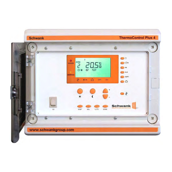
ThermoControl Plus 4M
Controller with four heating zones
Modulation or 2-stage control
(alternative: eight heating zones with 1-stage control)
Operating and
Installation Manual
Schwank Group
5285 Bradco Blvd., Mississauga, ON L4W 2A6
2 Schwank Way, Waynesboro, GA 30830
Tel.: 1-877-446-3727 Fax: 1-866-361-0523
csr@schwankgroup.com
www.schwankgroup.com
Version: v.2_ March 2021
Advertisement
Table of Contents

Related Manuals for Schwank ThermoControl Plus 4M


Summary of Contents for Schwank ThermoControl Plus 4M
- Page 1 Modulation or 2-stage control (alternative: eight heating zones with 1-stage control) Operating and Installation Manual Schwank Group 5285 Bradco Blvd., Mississauga, ON L4W 2A6 2 Schwank Way, Waynesboro, GA 30830 Tel.: 1-877-446-3727 Fax: 1-866-361-0523 csr@schwankgroup.com www.schwankgroup.com Version: v.2_ March 2021...
-
Page 2: Table Of Contents
Content: 1 INTRODUCTION ....................3 2 SAFETY ......................4 3 Structure and Function ..................5 4 OPERATION ....................... 6 4.1 Basic operational parameters................6 4.1.1 Further information ..................6 4.1.2 Selection of a heating zone ................7 4.1.3 Turning the selected zone on/off..............7 4.1.4 Special information on the default screen ............. -
Page 3: Introduction
1 Introduction The Schwank ThermoControl Plus 4M is suitable for the control of single or two-stage / modulation gas-infrared heating systems. Depending on the selected operation mode, the controller has 4 to 8 heating zones. Please read this manual carefully before installing or using the control unit. Failure to follow the manual and warnings will affect your warranty. -
Page 4: Safety
Make sure that nobody can connect appliance to the power supply while you are working. The Schwank ThermoControl Plus 4M has to be mounted on/at a place, where it’s not affected by vibrations or shocks. -
Page 5: Structure And Function
3 Structure and Function Front panel layout: 1. I/O Main switch on / off 2. LCD Display: All functional- and operating-information is shown on the default screen (picture above).The control unit switches back to the default screen, if no button is pushed for more than one minute. -
Page 6: Operation
4 Operation 4.1 Basic operational parameters By starting the ThermoControl with the I/O switch an automatic display-test is activated. The controller starts up with default settings. Afterwards the display jumps to the default screen, which shows all the important operational information. ID number of relay outputs and sensor inputs assigned to the currently selected heating zone. -
Page 7: Selection Of A Heating Zone
4.1.2 Selection of a heating zone The screen content, and adjustable parameters belong to the selected heating zone. The zone can be selected pushing ZONE button. After pushing the button, all settings of the heating zone can be adjusted and set. 4.1.3 Turning the selected zone on/off If you want to stop heating a certain zone, push the button. -
Page 8: Display And Change Of Day- And Night Time Temperature
4.2 Display and change of day- and night time temperature The desired temperature for every heating zone can be programmed separately. The current day- or night time temperatures can be displayed, if you push the button. The displayed values can be modified by pushing the buttons. -
Page 9: How To Read And Modify Time And Date
4.3. How to read and modify time and date To read and modify time and date, the button has to be pushed. All heating zones have a separate program schedule. This function takes place in the digital clock. At first the time is shown (in the picture: 14:03). Afterwards you have to use the button again, to be able to change the year (2021), after pushing the button for the third time month and... - Page 10 Setting the year After the time has been modified, you have to set the right year, month and day as well. Otherwise the automatic summer- / wintertime correction won’t work correctly. To change the year, you have to press the SEL button. The last two figures will start to blink (20), they can be modified with buttons.
-
Page 11: Scheduling
4.4 Timing Every heating zone has an independent schedule program, which can be modified. The time program is a series of different switching times or switching points. The controller changes automatically from daytime , to night time or frost protection mode . An on/off command can be described as: - time (hour and minute) - operation mode... -
Page 12: How To Clear A On/Off Program
4.4.2 How to clear a switching point If you want to clear an on/off command, you have to push and hold the CLR button. The symbol CLR will blink on the display, so that you are warned you are going to clear a on/ off command,. -
Page 13: How To Program The On/Off Commands
4.4.5 How to program the switching points In this example we program the following circumstance: The day temperature should start every morning at 7 :35 from Monday till Friday. First of all we are searching for a free on/off point by using the PR button. -
Page 14: Vacation Program
4.5 Vacation program The controller gives you the opportunity to program 8 vacation periods. Beginning and ending of the vacation is displayed with exact data (year, month, day). The programs can be changed or stopped anytime. During the vacation program the frost protection temperature will be maintained. To program the holiday periods, push the button. -
Page 15: Manual Operation Fix
4.6 Manual operation If you use the button, you are able to select different operating modes. To change the FIX mode you have to push button. Press DISP, if the desired operation mode appears (for example: continuous mode). The control unit switches back to the default screen and the selected mode is activated. -
Page 16: Set Up The Operating Parameters
5 Set up the operating parameters The setup parameters can be modified from the front panel. To modify the parameters you have to have technical knowledge, otherwise proper operation can not be guaranteed. Inside the controller there is a sliding switch to avoid unwanted functional changes, thus parameters can be locked. -
Page 17: Set Up The Parameters
5.2 Set up the parameters To set up the parameters please hold the DISP button for about 3 seconds. The „Par” symbol appears for a short time. parameters selected with the SEL button. Threshold value for second-stage: 0.5...3.0 °C / 1.0...5.5 ºF. Only in two-stage mode; in single- stage mode: --.-- Proportional range: 1.5...10.0 °C / 2.7...18.0 ºF. - Page 18 Minimal operation time of the heater. ( 0...15 min) Programmable time for the override button (0:00-24:00) ’OFF’: the exhaust fan is switched off (also the symbol doesn’t appear). ’AUto’: exhaust fan and air-proving contact in use. Exhaust fan follow-up-time After the heating zones have been switched off, the exhaust fan continues to run for a preset time.
-
Page 19: The Heat-Up Optimization
5.3 The Heat-up optimization The Heat-up optimization is only operational if an OAS sensor is connected to the controller. The program works automatically and doesn’t need to be adjusted. The Heat-up optimization follows an easy principal: the controller switches on the heater earlier than it is programmed, so the desired temperature is achieved at the favoured time. -
Page 20: How To Do A Security Save And How To Reload All Parameters
5.5 How to do a security save and how to reload all parameters: The Schwank-service technician can save all operational parameters as a package on a storage memory. In case of unintentional parameter changes, and functionality problems, the stored parameters can be restored. It is also possible to reload the default settings. -
Page 21: Important General Instructions
6.1 Important general instructions The appliance must be isolated from the power supply while installation or connection works are carried out! The "Off" position (O) of the main control switch I/O doesn’t indicate a complete zero potential of the controller! We recommend that the installation is to be carried out in accordance with the national local and any local Bye-laws and the UL wiring regulation. -
Page 22: Wiring Connections
6.4 Wiring connections - 22 -... - Page 23 - 23 -...
-
Page 24: Exhaust Fan Connection
6.5 Exhaust fan connection Only 24VAC Class 2 equipments can be connected to the controller ! Use 24VAC Class 2 rated power relays to connect exhaust fan that is operating with higher than extra low voltage. The ThermoControl Plus is provided with a exhaust fan control. The outputs of two heating zones belong to one common exhaust fan control. -
Page 25: Temperature Display ºf / ºc Selection
6.9. Temperature display ºF / ºC selection Select the ºF / ºC temperature display mode by a jumper (see figure 6.4 Wiring Connection ). Switch off power supply before making any operation with this jumper ! After selecting the readout all displays and settings will automatically appear with the selected mode. Default setting is ºF. -
Page 26: Common Error Signal
6.11 Common ERROR signal In case of any operational error the red “ERROR” symbol starts to blink, simultaneously the error relay switches on (terminals 1, 2, 3). The display shows the affected heating zone. Type and cause of the problem is shown as well by other symbols. To select another zone, press “ZONE”, but if you do so, the red “ERROR”... -
Page 27: Technical Parameters
7 Technical Parameters Relay outputs: 8 control relays (up to 8 heating zones), 4 exhaust fan relays. Relays switch 24VAC to connection terminals. 1 error relay: connected as potential-free contact to connection terminals Relay load: max. 6.3A 24V 50/60Hz (inductive) ≥... -
Page 28: Appendix
8 Appendix Wiring diagram ThermoControl Plus 4M 1-8 Zones, single-stage, luminous heater - 28 -... - Page 29 Wiring diagram ThermoControl Plus 4M 1-4 Zones, two-stage, luminous heater - 29 -...
- Page 30 Wiring diagram ThermoControl Plus 4M 1-8 Zones, single-stage, radiant tube heater - 30 -...
- Page 31 Wiring diagram ThermoControl Plus 4M 1-4 Zones, two-stage, radiant tube heater - 31 -...
- Page 32 Wiring diagram ThermoControl Plus 4M 1-4 Zones, modulation, radiant tube heater - 32 -...
- Page 33 Wiring diagram, accessories Option 1: Over ride button Option 2: Average temperature measurement, 4 SR sensor - 33 -...
Need help?
Do you have a question about the ThermoControl Plus 4M and is the answer not in the manual?
Questions and answers