Table of Contents
Advertisement
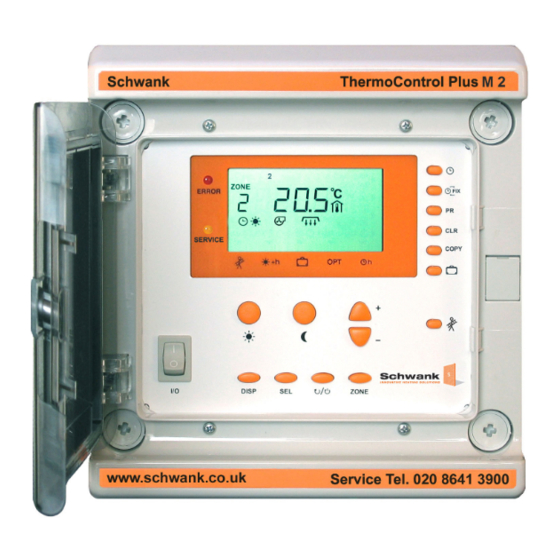
ThermoControl Plus M2
2-stage or modulating controller
with two control zones
(alternative: four control zones 1-stage)
Operating and
Installation Manual
Schwank GmbH - Bremerhavener Str. 43 - 50735 Cologne - Germany
Tel: +49 (0)221- 7176-0 Fax: +49 (0)221-7176-288
E-mail: info@schwank.de
Internet: www.schwank.de
Subject to technical changes. Version 09/10
Advertisement
Table of Contents

Related Manuals for Schwank ThermoControl Plus M2


Summary of Contents for Schwank ThermoControl Plus M2
- Page 1 (alternative: four control zones 1-stage) Operating and Installation Manual Schwank GmbH - Bremerhavener Str. 43 - 50735 Cologne - Germany Tel: +49 (0)221- 7176-0 Fax: +49 (0)221-7176-288 E-mail: info@schwank.de Internet: www.schwank.de Subject to technical changes. Version 09/10...
-
Page 2: Table Of Contents
Content: 1 INTRODUCTION ....................3 2 YOUR SAFETY ....................4 3 STRUCTURE AND FUNCTION ................5 4 OPERATION ....................... 6 4.1 Basic knowledge of operation ..............6 4.1.1 Further readable information ..............6 4.1.2 Selection of the control zone ..............7 4.1.3 Activation and deactivation of the shown control-zone...... -
Page 3: Introduction
1 Introduction The Schwank ThermoControl Plus M2 is suitable for 1-stage, 2-stage or modulating gas- infrared heating systems as well as for gas-fired warm air heaters. Dependant upon its operation the controller has two or four control zones. Please read this manual carefully before installing or using the control-unit. Failure to follow the notes and warnings will affect your guarantees. -
Page 4: Your Safety
Settins and modification of the The Schwank ThermoControl Plus 2 function parameters can be carried has to be mounted on/at a place, out only by Schwank service where it’s not affected by vibrations... -
Page 5: Structure And Function
To turn on/off the single control circuits. 15. SERVICE „Maintenance”: If this sign appears the system needs maintenance, please call the official Schwank service. Button to program holiday operation mode. Button for chimney-sweep operation mode: all control circuits heat full load. -
Page 6: Operation
4 Operation 4.1 Basic knowledge of operation By starting the ThermoControl Plus M with the I/O -button an automatic display-test is activated. The controller starts up with the factory-made standard-program. Afterwards the display switches to the base-program, which shows all the important operational information. This number informs: which relay output and which sensor inputs are used in the specific control circuit. -
Page 7: Selection Of The Control Zone
4.1.2 Selection of the control zone The display of the controller and its usage is based on the display of the control circuit. The control zone can be chosen by pushing the ZONE button. Now, all settings of the control zones can be managed and progressed. -
Page 8: Display And Change Of Day- And Night Temperature
4.2 Display and change of day- and night temperature The desired temperature for every control circuit can be programmed separately. The current day- or night- temperatures can be displayed, if you push button. The displayed values can be modified by pushing All modifications are saved immediately. -
Page 9: How To Read And Modify Time And Date
4.3. How to read and modify time and date To read and modify time and date, the button has to be pushed. All control circuits include a separate time-program. This function takes place at the collective clock. At first the time is shown (in the picture: 14:03). Afterwards you have to use the button again, to be able to change the year (2007), after pushing the button for the third time month... - Page 10 Setting the year After the time has been modified, you have to set the right year, month and day as well. Otherwise the automatic summer- / wintertime correction won’t work correctly. To change the year, you have to press the SEL button. The last two figures will start to blink (06), they can be modified with the...
-
Page 11: Timing
4.4 Timing Every control circuit has an independent time program, which is able to be modified. The time program is a series of different circuit times. The controller changes automatically from day- , to night- or antifreeze mode- A circuit/switching point of time can be described as: - time (hour and minute) - temperature mode , which will start at this point of time... -
Page 12: How To Clear A Switching Point
4.4.2 How to clear a switching point If you want to clear a switching point, you have to push and hold the CLR button. The symbol CLR will blink in the display, so that you are warned you are going to clear a switching point. -
Page 13: How To Program The Switching Points
4.4.5 How to program the switching points In this example we program the following circumstance: The day temperature should start every morning at 7:35 from Monday till Friday. First of all we are searching for a free switching point by using the PR button. -
Page 14: Holiday Program
4.5 Holiday program The controller gives you the opportunity to program 8 holiday phases. Beginning and ending of the holidays is displayed with exact data (year, month, day). The programs can be changed and also stopped at every point of time. During the holiday program the anti-freezing temperature will be maintained. -
Page 15: Manual Operation
4.6 Manual operation If you use the button, you are able to select different operating modes. To change the FIX mode you have to push the button. Press DISP, if the desired operation mode appears (for example: continuous FIX mode). The control- unit switches back to the main display and the selected mode is activated. -
Page 16: Set Up The Operating Parameters
5 Set up the operating parameters The set up is made with the buttons on the front. To modify the parameters you have to have technical knowledge, otherwise a faultless function might not be maintained. To avoid unwanted modifications a special procedure must be carried out to open parameter settings. -
Page 17: Set Up The Parameters In The Display
5.2 Set up the parameters in the display Parameter set up is a protected function. A special process must be carried out to enable modification. In basic mode parameters can be displayed by DISP and SEL buttons but modification is not allowed. To set up the parameters please hold the DISP button for circa 3 seconds. -
Page 18: The Warm Up Time Optimiser
Programmable time for the override button +h (0:00-24:00) Switch off the extract fans: ’AUt’: extract fan in use, ’OFF’’: the extract fan is switched off (also the symbol doesn’t appear). Extract fan follow-up-time : After the heating circuits have been switched off, the extract fan continues until the programmed time is achieved. -
Page 19: Copy
5.4 COPY The COPY button offers you the opportunity to copy all parameters of a certain circuit or the omplete time program and insert it into the program of one or many other control circuits. To copy parameters hold DISP (approx. -
Page 20: How To Do A Security Save And How To Reload All Parameters
5.5 How to do a security save and how to reload all parameters: The Schwank-service technician can save all operational parameters as a package on a save memory card. In case of changing the parameters unintentionally and a resulting functional damage causes problems in the system, the system can be modified to the old parameters easily, according to the purpose built memory card. -
Page 21: Installation
6 Installation Bracket Lower part Door Upper part Screw Lock 6.1 General security instructions The appliance must be isolated from the power supply while installation- or connection works are carried out! The disconnection of the main control switch I/O doesn’t indicate a complete zero potential of the controller! We recommend that all installation works have to be carried out in accordance with the national “Rules in Force”, any local Bye-laws and the IEE wiring regulation. -
Page 22: Maximum Load
6.4 Maximum load The maximum inductive load of heater- and extract fan output current achieves a value of 10 A 230V/50Hz. If the outputs also feed high capacity motors, you have to consider, that the starting current reaches a value, which is three- or four times higher than the nominal current input.. The limit of 10 A might be exceeded. -
Page 23: Remote-Control
6.8 Remote-Control The feature Remote-Control can be selected in the SETUP-Menu (5-2). The controller switches to day mode in both zones, if the remote contact is activated. The display showes the symbol. In case of not using the remote contact, you have to bypass the clamps. If the remote contact is activated it is not possible to change the operating mode by using the... -
Page 24: Common Fault Signal
6.10 Common fault signal In case of any operational error the red “ERROR” symbol starts to blink, simultaneously the error relay switches on (clamps 1, 2, 3). The display shows the affected control zone. Type and cause of the problem is shown as well by other symbols. To select another control zone press “ZONE”, but if you do so, the red “ERROR”... -
Page 25: Technical Parameters
7 Technical Parameters Relay outputs: 4 control relays (1 to 4 heating zones), 2 ventilator relays, 1 error relay Load: max. 10A 230V/50Hz (inductive) Inputs: Temperature sensor: 2-wire connection RTF black hemispherical temperature sensor ATF: outside temperature sensor Contact inputs: potential free contacts, closed if not used Alarm contacts Remote : Forced day mode operation contacts or signal input fault... -
Page 26: Appendix
8 Appendix Wiring diagram ThermoControl Plus M 1, 2, 4 1-8 zones, single-stage, luminous heater - 26 -... - Page 27 Wiring diagram ThermoControl Plus M 1, 2, 4 1-4 zones, two-stage, luminous heater - 27 -...
- Page 28 Wiring diagram ThermoControl Plus M 1, 2, 4 1-4 zones, modulating, luminous heater - 28 -...
- Page 29 Wiring diagram ThermoControl Plus M 1, 2, 4 1-8 zones, single-stage, tube heater - 29 -...
- Page 30 Wiring diagram ThermoControl Plus M 1, 2, 4 1-4 zones, two-stage, tube heater - 30 -...
- Page 31 Wiring diagram ThermoControl Plus M 1, 2, 4 1-4 zones, modulating, tube heater - 31 -...
- Page 32 Wiring diagram ThermoControl Plus M 1, 2, 4 1-4 zones, warm air heater, aeroSchwank AR and AT - 32 -...
- Page 33 Wiring diagram, warm air heater, AR and AT - 33 -...
- Page 34 Temperature Sensor-Characteristic Line ThermoControl Plus 16000 14000 12000 10000 8000 6000 4000 2000 Temperature ° C Temp. ° C Ohmic Resistance [ ] 14317 13682 13048 12413 11778 11144 10663 10182 9701 9221 8740 8373 8006 7638 7271 6904 6622 6339 6057 5775...